
K family - Practical Control
33
Tecnologic S.p.A. K family communication protocol S.p.A. - Via Indipendenza, 56 - Vigevano Titolo documento : Manuale del protocollo di comunicazione ver Inglese Codice documento : K-series.protocol.GB02.CP.DOC Codice mag.: Sostituisce codice : Codice mag.: E' sostituito da : Codice mag.: Codice commessa : Sezione : Modulo: Totale pagine : 33 Genere documento : Sig.doc : Vers : 02 Compilato : Carlo Pisani Verificato : Approvato : Data : 23/09/09 Data : Data : Variazioni rispetto al documento precedente: K family Communication protocol user's guide 1
Transcript of K family - Practical Control
Tecnologic S.p.A. K family communication protocol
S.p.A. - Via Indipendenza, 56 - Vigevano
Titolo documento : Manuale del protocollo di comunicazione ver Inglese
Codice documento : K-series.protocol.GB02.CP.DOC Codice mag.:
Sostituisce codice : Codice mag.:
E' sostituito da : Codice mag.:
Codice commessa : Sezione : Modulo: Totale pagine : 33
Genere documento : Sig.doc : Vers : 02
Compilato : Carlo Pisani Verificato : Approvato :
Data : 23/09/09 Data : Data :
Variazioni rispetto al documento precedente:
K family
Communication protocol
user's guide
1
Tecnologic S.p.A. K family communication protocol
INDEX
1 Preface .............................................................................................................................4
2 Physical connection ..........................................................................................................5
2.1 Interface.....................................................................................................................................5
2.2 Line............................................................................................................................................5
3 Communication protocol....................................................................................................6
3.1 Function 3 - read n word..........................................................................................................7
3.2 Function 6 - one word write.....................................................................................................8
3.3 The exception replay................................................................................................................9
3.4 Cyclic redundancy check (CRC)...........................................................................................10
4 Data exchange................................................................................................................12
4.1 Some definitions......................................................................................................................12
4.2 Memory zones.........................................................................................................................13
4.2.1 Variables zones.........................................................................................................134.2.2 Parameters programming .........................................................................................154.2.3 Identification code zone.............................................................................................25
5 Performance....................................................................................................................25
2
Tecnologic S.p.A. K family communication protocol
1 Preface
This document is intended to describe the TLK series controllers using the MODBUSprotocol in their communication capability and is mainly directed to technicians, systemintegrators and software developers.
The subject is subdivided in four levels of interest:
Ÿ first level describes the physical connection to the line;
Ÿ second level presents the data link protocol, that is a subset of the MODBUS RTU (JBUS)protocol;
Ÿ third level describes in detail each data that can be exchanged;
Ÿ fourth level states performance characteristics of the system.
3
Tecnologic S.p.A. K family communication protocol
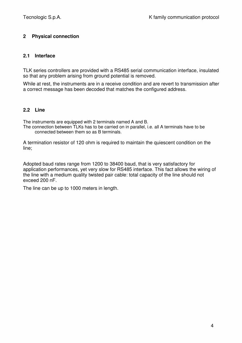
2 Physical connection
2.1 Interface
TLK series controllers are provided with a RS485 serial communication interface, insulatedso that any problem arising from ground potential is removed.
While at rest, the instruments are in a receive condition and are revert to transmission aftera correct message has been decoded that matches the configured address.
2.2 Line
The instruments are equipped with 2 terminals named A and B.The connection between TLKs has to be carried on in parallel, i.e. all A terminals have to be
connected between them so as B terminals.
A termination resistor of 120 ohm is required to maintain the quiescent condition on theline;
Adopted baud rates range from 1200 to 38400 baud, that is very satisfactory forapplication performances, yet very slow for RS485 interface. This fact allows the wiring ofthe line with a medium quality twisted pair cable: total capacity of the line should notexceed 200 nF.
The line can be up to 1000 meters in length.
4
Tecnologic S.p.A. K family communication protocol
3 Communication protocolThe protocol adopted by TLK series is a subset of the widely used MODBUS RTU (JBUS)1
protocol, so that connections are easy for many commercial PLCs and supervisoryprograms.
For users needing to develop their own communication software, all information isavailable as well as implementation hints.
The MODBUS RTU (JBUS) communication functions implemented in TLK series are:
Ÿ function 3 - n word read
Ÿ function 6 - one word write.
These functions allow the supervisory program to read and modify any data of thecontroller.
The communication is based on messages sent by the master station (host) to the slavestations (TLK) and viceversa.
The slave station that recognises the message as sent to it, analyses the content and, if itis formally and semantically correct, generates a reply message directed back to themaster.
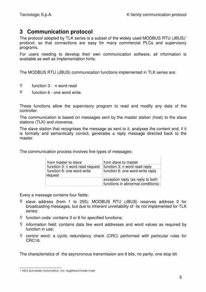
The communication process involves five types of messages:
from master to slave from slave to master
function 3: n word read request function 3: n word read reply function 6: one word writerequest
function 6: one word write reply
exception reply (as reply to bothfunctions in abnormal conditions)
Every a message contains four fields:
Ÿ slave address (from 1 to 255): MODBUS RTU (JBUS) reserves address 0 forbroadcasting messages, but due to inherent unreliability of its not implemented for TLKseries;
Ÿ function code: contains 3 or 6 for specified functions;
Ÿ information field: contains data like word addresses and word values as required byfunction in use;
Ÿ control word: a cyclic redundancy check (CRC) performed with particular rules forCRC16.
The characteristics of the asyncronous transmission are 8 bits, no parity, one stop bit.
1 AEG Schneider Automation, Inc. registered trade mark
5

Tecnologic S.p.A. K family communication protocol
3.1 Function 3 - read n word
The number of words to be read must be less or equal four.
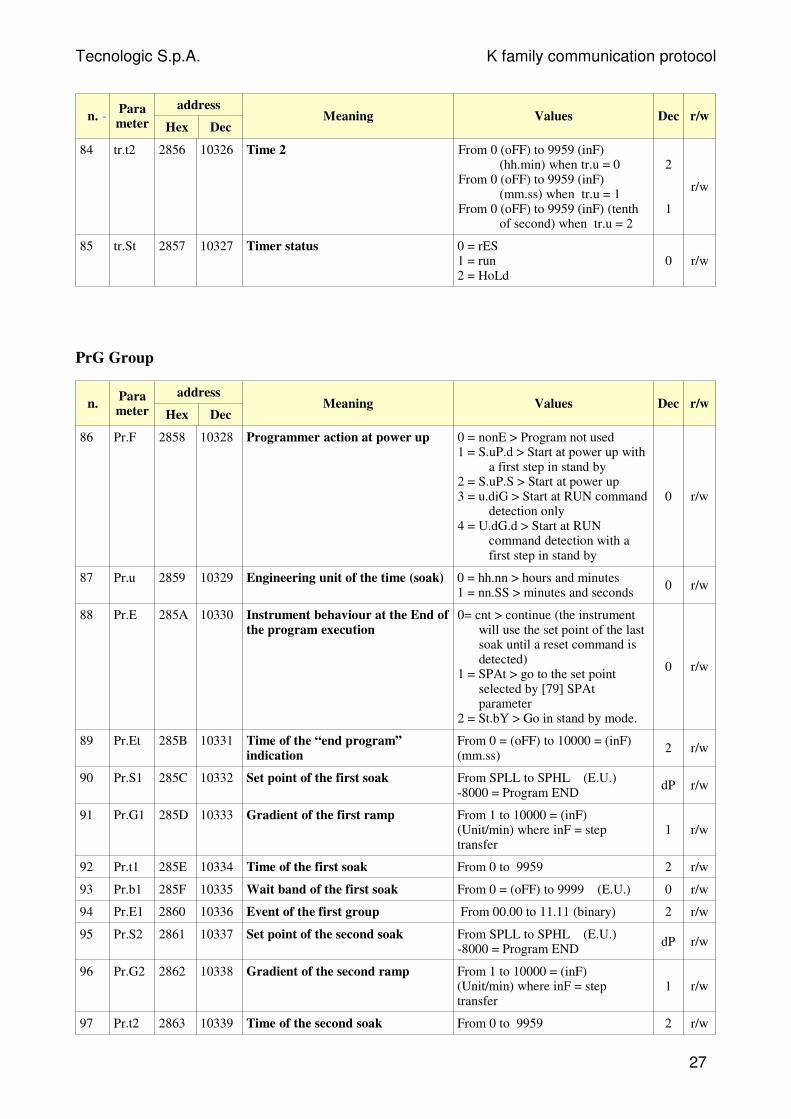
The request has the following frame:
slavenumber 3
first word address MSB LSB
number of words MSB LSB
CRC LSB MSB
byte 0 byte 1 byte 2 byte 3 byte 4 byte 5 byte 6 byte 7
The normal reply (as opposed to exception reply) has the following frame:
slavenumber 3
NBnumber ofread bytes
value of first wordMSB LSB
followingwords
CRC LSB MSB
byte 0 byte 1 byte 2 byte 3 byte 4 byte 5 byte NB + 2
byteNB + 3
6
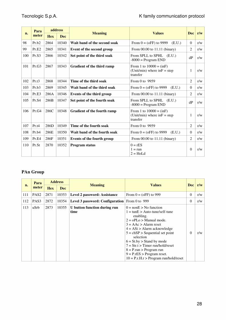
Tecnologic S.p.A. K family communication protocol
3.2 Function 6 - one word write
The request has the following frame:
slavenumber 6
word address MSB LSB
value to write MSB LSB
CRC LSB MSB
byte 0 byte 1 byte 2 byte 3 byte 4 byte 5 byte 6 byte 7
The normal reply (as opposed to exception reply) is merely an echo of the requestmessage:
slavenumber 6
word address MSB LSB
value to write MSB LSB
CRC LSB MSB
byte 0 byte 1 byte 2 byte 3 byte 4 byte 5 byte 6 byte 7
7
Tecnologic S.p.A. K family communication protocol
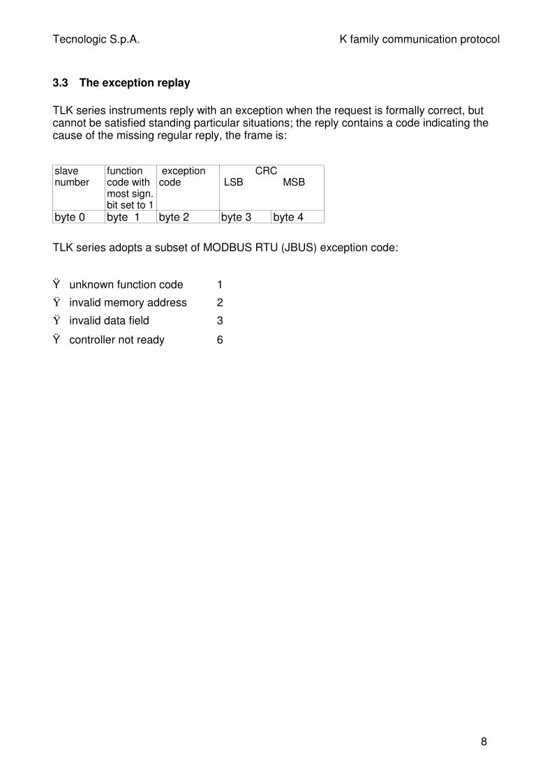
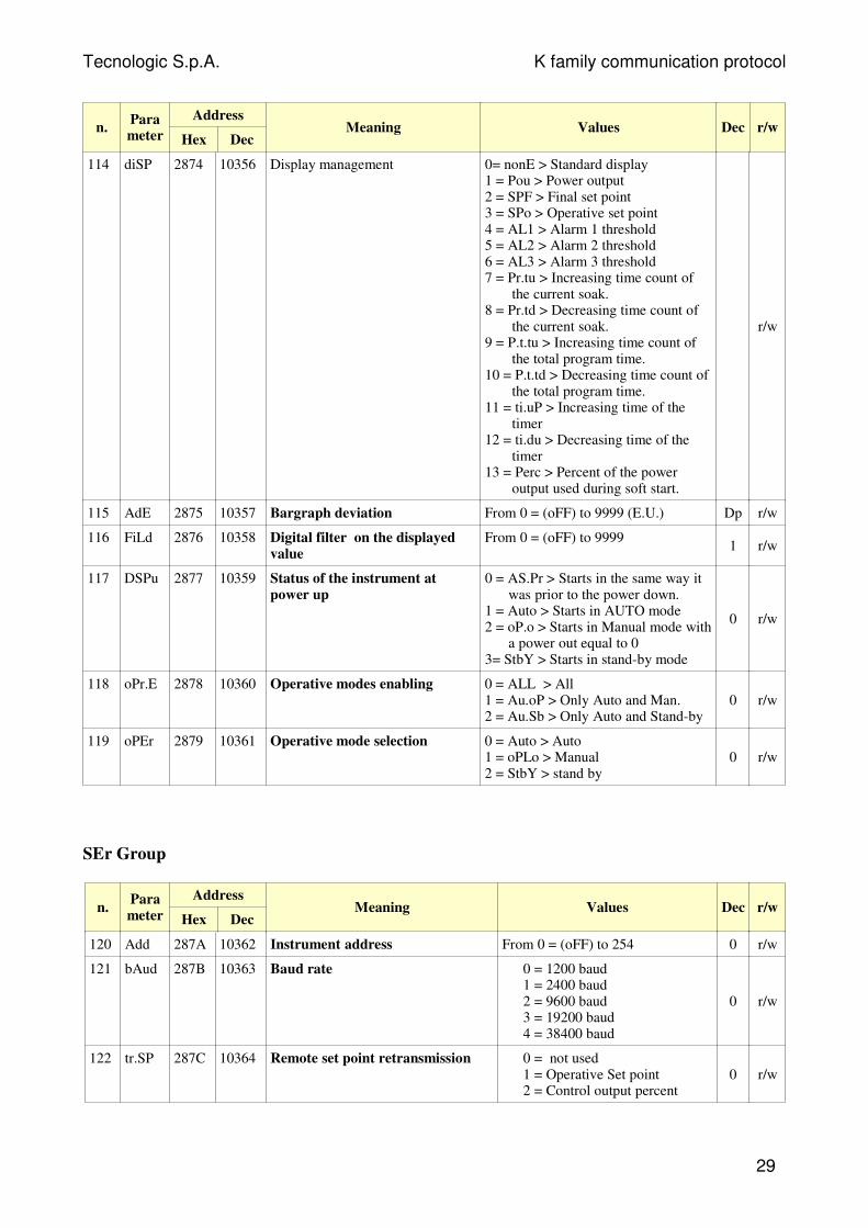
3.3 The exception replay
TLK series instruments reply with an exception when the request is formally correct, butcannot be satisfied standing particular situations; the reply contains a code indicating thecause of the missing regular reply, the frame is:
slavenumber
functioncode withmost sign.bit set to 1
exceptioncode
CRC LSB MSB
byte 0 byte 1 byte 2 byte 3 byte 4
TLK series adopts a subset of MODBUS RTU (JBUS) exception code:
Ÿ unknown function code 1
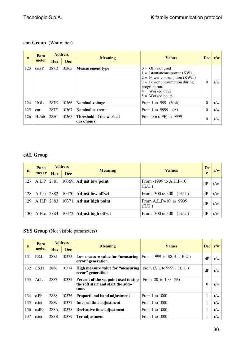
Ÿ invalid memory address 2
Ÿ invalid data field 3
Ÿ controller not ready 6
8
Tecnologic S.p.A. K family communication protocol
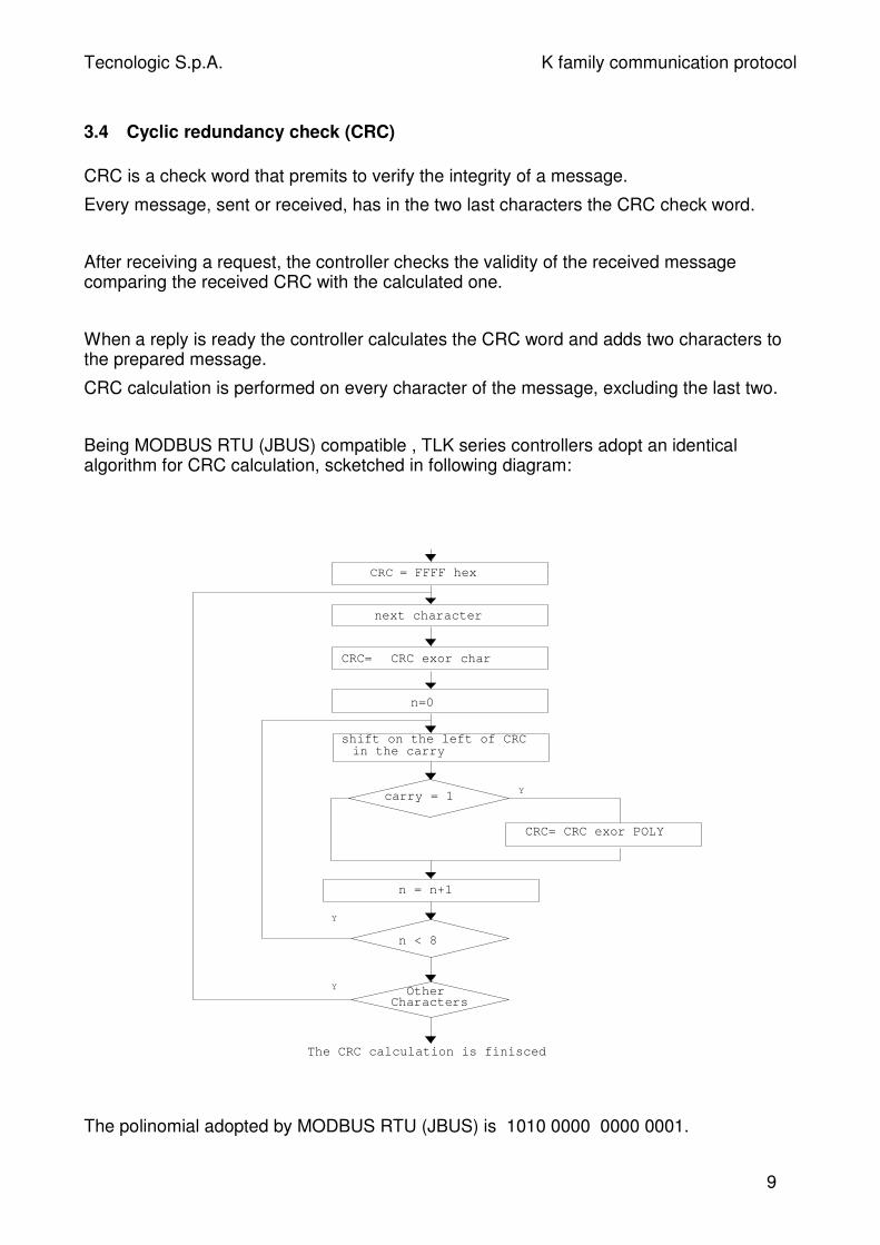
3.4 Cyclic redundancy check (CRC)
CRC is a check word that premits to verify the integrity of a message.
Every message, sent or received, has in the two last characters the CRC check word.
After receiving a request, the controller checks the validity of the received messagecomparing the received CRC with the calculated one.
When a reply is ready the controller calculates the CRC word and adds two characters tothe prepared message.
CRC calculation is performed on every character of the message, excluding the last two.
Being MODBUS RTU (JBUS) compatible , TLK series controllers adopt an identicalalgorithm for CRC calculation, scketched in following diagram:
The polinomial adopted by MODBUS RTU (JBUS) is 1010 0000 0000 0001.
9
OtherCharacters
CRC = FFFF hex
CRC exor charCRC=
n=0
shift on the left of CRC in the carry
carry = 1
CRC= CRC exor POLY
n = n+1
Y
Y
Y
The CRC calculation is finisced
next character
n < 8

Tecnologic S.p.A. K family communication protocol
Note: the first transmitted character of the CRC word is the least significant betweencalculated bytes.
.
10
Tecnologic S.p.A. K family communication protocol
4 Data exchange
This section contains informations about data exchanged with TLK series controllersconcerning numerical and not numerical data, with their formats and limits.
4.1 Some definitions
All exchanged data are in the form of 16 bit words.
Two types of data are distinguished: numerical and symbolic (or not numerical).
Numerical data represents the value of a quantity (e.g. the measured variable, the setpoint).
Symbolic data represents a particular value in a set of values (e.g. the thermocouple typein the set of available ones : J,K,S...).
Both types are coded as integers number : signed numbers for numerical and unsignednumbers for symbolic.
A numerical data, coded as an integer, is coupled with appropriate number of decimaldigits to represent a quantity with the same engineering units adopted aboard theinstrument.
Numerical data are in fixed point representation; however we make a distinction betweentwo kinds of data:
Ÿ the first kind has determined and unmodifiable decimal point position;
Ÿ the second has programmable decimal point position (dP parameter).
11
Tecnologic S.p.A. K family communication protocol
4.2 Memory zones
All readable and writable data appear to be allocated as 16 bit words in the memory of theinstrument.
The memory map has three zones:
Ÿ varaibles,
Ÿ parameters,
Ÿ instrument identification code.
Following parameters explore the characteristics of each zone.
4.2.1 Variables zones
In this zone there is a collection of main TLK controller variables, it is a group of frequentlycomputed or updated data residing in volatile memory.
MOST IMPORTANT CHANGE
A) during parameter modification by push-button, the serial interface continue to operatewithout any "limit" (you can see by serial link the value of all parameters and you can set italso)
B) When you write a value in a location the instrument will operate as follows:
B.1) if you write a value within parameter range, the instrument will accept it; the newvalue will be memorized and the instrument will send back the standard answer.
B.2) If you try to write a value OUT of parameter range, the instrument will refuse thenew value; the new value will NOT be memorized and the instrument will send anexception message to the master.
These are available data:
12
Tecnologic S.p.A. K family communication protocol
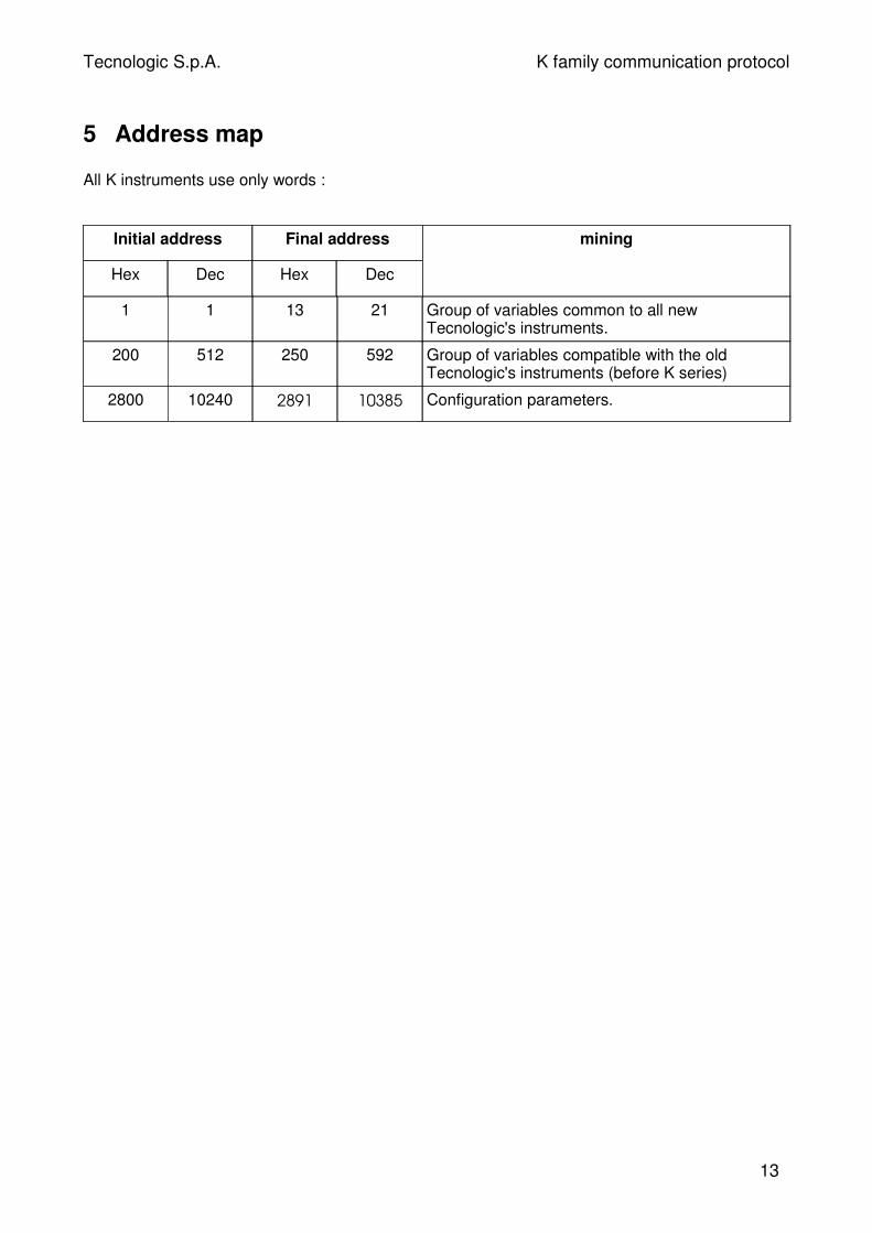
5 Address map
All K instruments use only words :
Initial address Final address
Hex Dec Hex Dec
mining
1 1 13 21 Group of variables common to all newTecnologic's instruments.
200 512 250 592 Group of variables compatible with the oldTecnologic's instruments (before K series)
2800 10240 2891 10385 Configuration parameters.
13
Tecnologic S.p.A. K family communication protocol
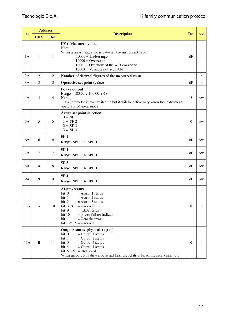
n.Address
HEX Dec.Description Dec r/w
1A 1 1
PV : Measured valueNote:When a measuring error is detected the instrument send:
-10000 = Underrange 10000 = Overrange 10001 = Overflow of the A/D converter 10003 = Variable not available
dP r
2A 2 2 Number of decimal figures of the measured value r
3A 3 3 Operative set point (value) dP r
4A 4 4
Power output Range: -100.00 ÷ 100.00 (%)Note: This parameter is ever writeable but it will be active only when the instrumentoperate in Manual mode.
2 r/w
5A 5 5
Active set point selection 0 = SP 1 1 = SP 2 2 = SP 3 3 = SP 4
0 r/w
6A 6 6SP 1
Range: SPLL ÷ SPLHdP r/w
7A 7 7SP 2
Range: SPLL ÷ SPLHdP r/w
8A 8 8SP 3
Range: SPLL ÷ SPLHdP r/w
9A 9 9SP 4
Range: SPLL ÷ SPLHdP r/w
10A A 10
Alarms status bit 0 = Alarm 1 statusbit 1 = Alarm 2 statusbit 2 = Alarm 3 statusbit 3÷8 = reservedbit 9 = LBA statusbit 10 = power feilure indicatorbit 11 = Generic errorbit 12÷15 = reserved
0 r
11A B 11
Outputs status (physical outputs) bit 0 = Output 1 statusbit 1 = Output 2 statusbit 3 = Output 3 statusbit 4 = Output 4 statusbit 5÷15 = ReservedWhen an output is driven by serial link, the relative bit will remain equal to 0.
0 r
14
Tecnologic S.p.A. K family communication protocol
n.Address
HEX Dec.Description Dec r/w
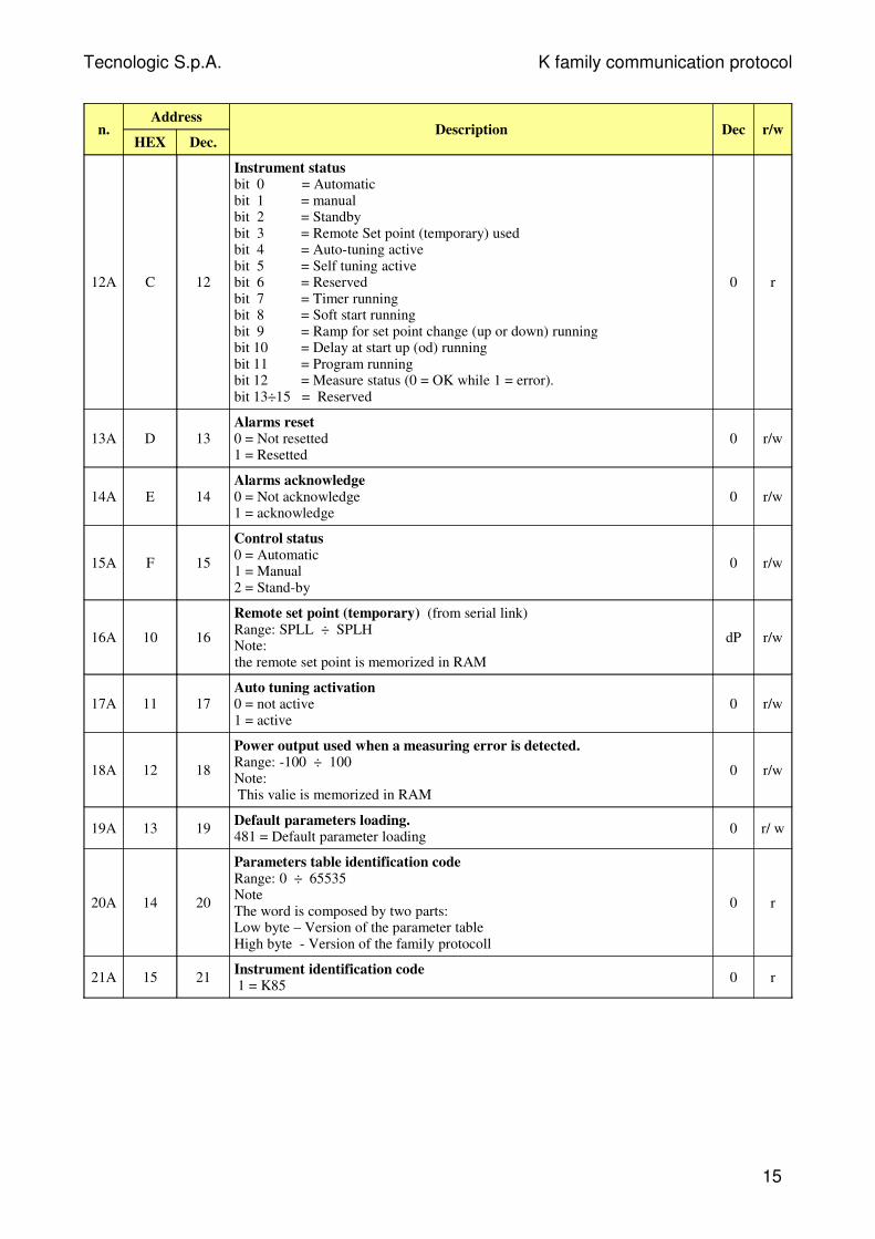
12A C 12
Instrument statusbit 0 = Automaticbit 1 = manualbit 2 = Standbybit 3 = Remote Set point (temporary) usedbit 4 = Auto-tuning activebit 5 = Self tuning activebit 6 = Reservedbit 7 = Timer runningbit 8 = Soft start runningbit 9 = Ramp for set point change (up or down) runningbit 10 = Delay at start up (od) runningbit 11 = Program runningbit 12 = Measure status (0 = OK while 1 = error).bit 13÷15 = Reserved
0 r
13A D 13Alarms reset0 = Not resetted1 = Resetted
0 r/w
14A E 14Alarms acknowledge 0 = Not acknowledge1 = acknowledge
0 r/w
15A F 15
Control status0 = Automatic 1 = Manual2 = Stand-by
0 r/w
16A 10 16
Remote set point (temporary) (from serial link)Range: SPLL ÷ SPLH Note:the remote set point is memorized in RAM
dP r/w
17A 11 17Auto tuning activation0 = not active1 = active
0 r/w
18A 12 18
Power output used when a measuring error is detected.Range: -100 ÷ 100Note: This valie is memorized in RAM
0 r/w
19A 13 19Default parameters loading.481 = Default parameter loading
0 r/ w
20A 14 20
Parameters table identification codeRange: 0 ÷ 65535NoteThe word is composed by two parts:Low byte – Version of the parameter table High byte - Version of the family protocoll
0 r
21A 15 21Instrument identification code 1 = K85
0 r
15
Tecnologic S.p.A. K family communication protocol
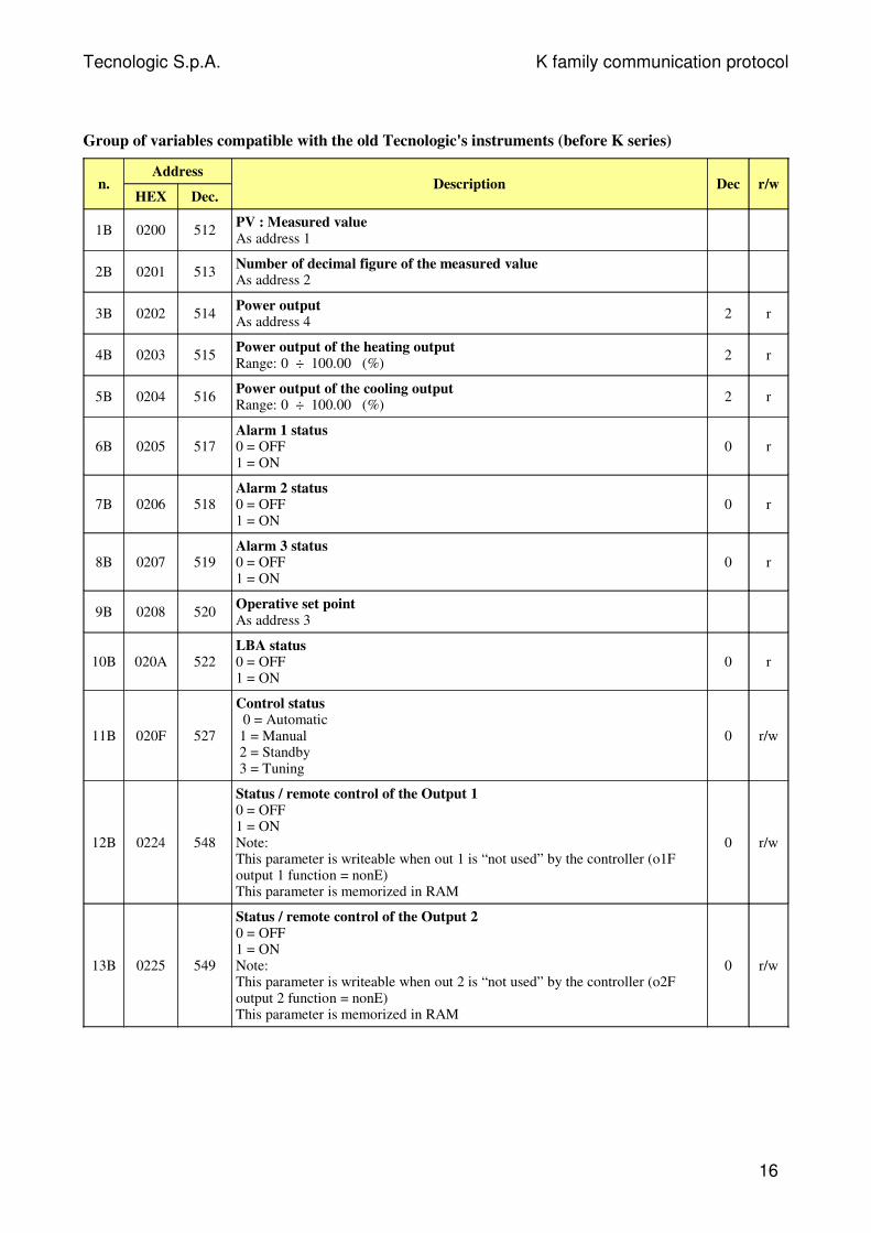
Group of variables compatible with the old Tecnologic's instruments (before K series)
n.Address
HEX Dec.Description Dec r/w
1B 0200 512PV : Measured value As address 1
2B 0201 513Number of decimal figure of the measured valueAs address 2
3B 0202 514Power outputAs address 4
2 r
4B 0203 515Power output of the heating outputRange: 0 ÷ 100.00 (%)
2 r
5B 0204 516Power output of the cooling output Range: 0 ÷ 100.00 (%)
2 r
6B 0205 517Alarm 1 status0 = OFF1 = ON
0 r
7B 0206 518Alarm 2 status0 = OFF1 = ON
0 r
8B 0207 519Alarm 3 status0 = OFF1 = ON
0 r
9B 0208 520Operative set pointAs address 3
10B 020A 522LBA status0 = OFF1 = ON
0 r
11B 020F 527
Control status 0 = Automatic 1 = Manual 2 = Standby 3 = Tuning
0 r/w
12B 0224 548
Status / remote control of the Output 10 = OFF1 = ONNote: This parameter is writeable when out 1 is “not used” by the controller (o1Foutput 1 function = nonE) This parameter is memorized in RAM
0 r/w
13B 0225 549
Status / remote control of the Output 20 = OFF1 = ONNote: This parameter is writeable when out 2 is “not used” by the controller (o2Foutput 2 function = nonE) This parameter is memorized in RAM
0 r/w
16
Tecnologic S.p.A. K family communication protocol
n.Address
HEX Dec.Description Dec r/w
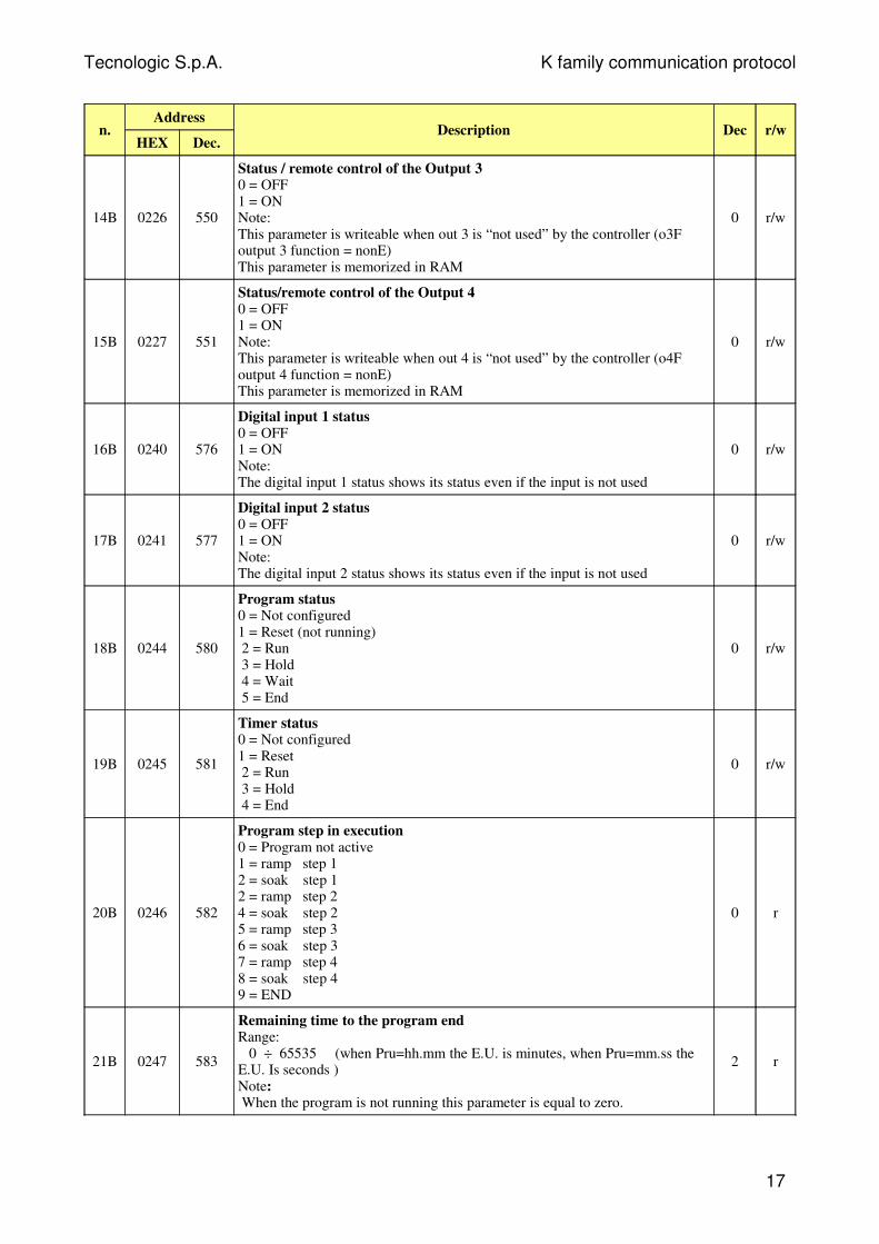
14B 0226 550
Status / remote control of the Output 30 = OFF1 = ONNote: This parameter is writeable when out 3 is “not used” by the controller (o3Foutput 3 function = nonE) This parameter is memorized in RAM
0 r/w
15B 0227 551
Status/remote control of the Output 40 = OFF1 = ONNote: This parameter is writeable when out 4 is “not used” by the controller (o4Foutput 4 function = nonE) This parameter is memorized in RAM
0 r/w
16B 0240 576
Digital input 1 status0 = OFF1 = ONNote:The digital input 1 status shows its status even if the input is not used
0 r/w
17B 0241 577
Digital input 2 status 0 = OFF1 = ONNote:The digital input 2 status shows its status even if the input is not used
0 r/w
18B 0244 580
Program status 0 = Not configured1 = Reset (not running) 2 = Run 3 = Hold 4 = Wait 5 = End
0 r/w
19B 0245 581
Timer status 0 = Not configured 1 = Reset 2 = Run 3 = Hold 4 = End
0 r/w
20B 0246 582
Program step in execution0 = Program not active1 = ramp step 12 = soak step 12 = ramp step 24 = soak step 25 = ramp step 36 = soak step 37 = ramp step 48 = soak step 49 = END
0 r
21B 0247 583
Remaining time to the program endRange: 0 ÷ 65535 (when Pru=hh.mm the E.U. is minutes, when Pru=mm.ss theE.U. Is seconds )Note: When the program is not running this parameter is equal to zero.
2 r
17
Tecnologic S.p.A. K family communication protocol
n.Address
HEX Dec.Description Dec r/w
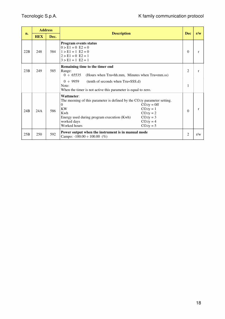
22B 248 584
Program events status0 > E1 = 0 E2 = 01 > E1 = 1 E2 = 02 > E1 = 0 E2 = 13 > E1 = 1 E2 = 1
0 r
23B 249 585Remaining time to the timer endRange: 0 ÷ 65535 (Hours when Tru=hh.mm, Minutes when Tru=mm.ss)
2 r
0 ÷ 9959 (tenth of seconds when Tru=SSS.d)Note: When the timer is not active this parameter is equal to zero.
1
24B 24A 586
Wattmeter:The meening of this parameter is defined by the CO.ty parameter setting.0 CO.ty = 0ffKW CO.ty = 1 Kwh CO.ty = 2 Energy used during program execution (Kwh) CO.ty = 3 worked days CO.ty = 4Worked hours CO.ty = 5
0r
25B 250 592Power output when the instrument is in manual modeCampo: -100.00 ÷ 100.00 (%)
2 r/w
18
Tecnologic S.p.A. K family communication protocol
Configuration parameters
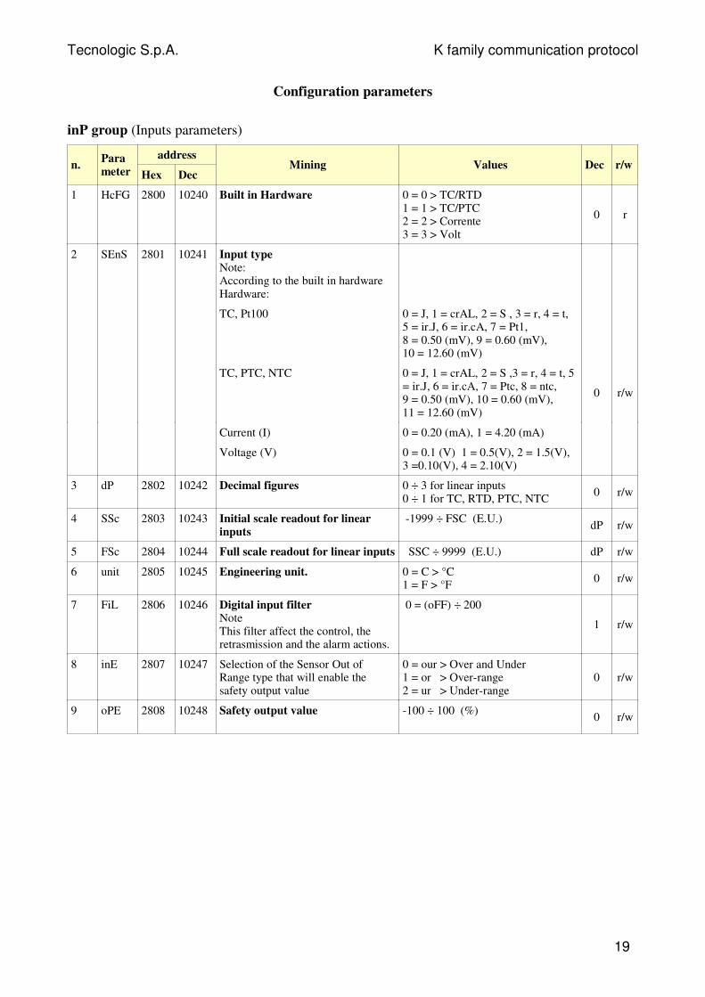
inP group (Inputs parameters)
n.Parameter
address
Hex DecMining Values Dec r/w
1 HcFG 2800 10240 Built in Hardware 0 = 0 > TC/RTD1 = 1 > TC/PTC2 = 2 > Corrente3 = 3 > Volt
0 r
2 SEnS 2801 10241 Input typeNote:According to the built in hardwareHardware:
TC, Pt100 0 = J, 1 = crAL, 2 = S , 3 = r, 4 = t, 5 = ir.J, 6 = ir.cA, 7 = Pt1,8 = 0.50 (mV), 9 = 0.60 (mV), 10 = 12.60 (mV)
TC, PTC, NTC 0 = J, 1 = crAL, 2 = S ,3 = r, 4 = t, 5= ir.J, 6 = ir.cA, 7 = Ptc, 8 = ntc, 9 = 0.50 (mV), 10 = 0.60 (mV), 11 = 12.60 (mV)
0 r/w
Current (I) 0 = 0.20 (mA), 1 = 4.20 (mA)
Voltage (V) 0 = 0.1 (V) 1 = 0.5(V), 2 = 1.5(V),3 =0.10(V), 4 = 2.10(V)
3 dP 2802 10242 Decimal figures 0 ÷ 3 for linear inputs0 ÷ 1 for TC, RTD, PTC, NTC
0 r/w
4 SSc 2803 10243 Initial scale readout for linearinputs
-1999 ÷ FSC (E.U.)dP r/w
5 FSc 2804 10244 Full scale readout for linear inputs SSC ÷ 9999 (E.U.) dP r/w
6 unit 2805 10245 Engineering unit. 0 = C > °C1 = F > °F
0 r/w
7 FiL 2806 10246 Digital input filterNoteThis filter affect the control, theretrasmission and the alarm actions.
0 = (oFF) ÷ 200
1 r/w
8 inE 2807 10247 Selection of the Sensor Out ofRange type that will enable thesafety output value
0 = our > Over and Under1 = or > Over-range2 = ur > Under-range
0 r/w
9 oPE 2808 10248 Safety output value -100 ÷ 100 (%)0 r/w
19
Tecnologic S.p.A. K family communication protocol
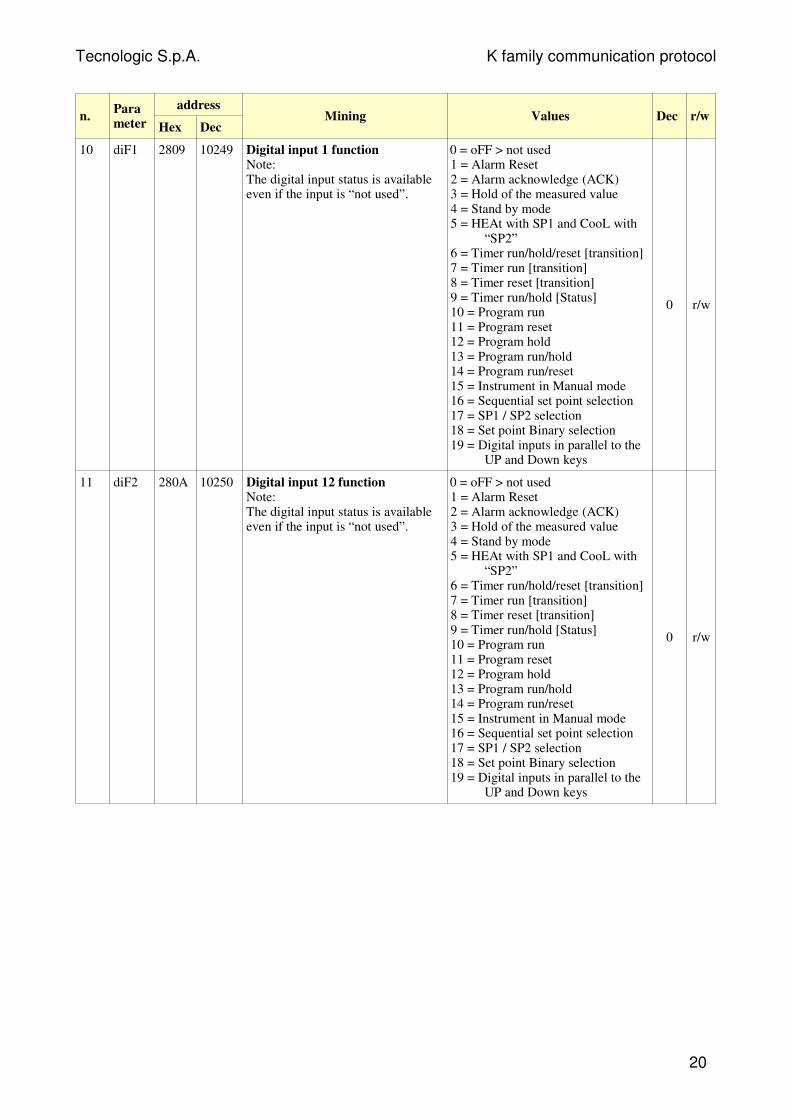
n.Parameter
address
Hex DecMining Values Dec r/w
10 diF1 2809 10249 Digital input 1 functionNote:The digital input status is availableeven if the input is “not used”.
0 = oFF > not used1 = Alarm Reset2 = Alarm acknowledge (ACK)3 = Hold of the measured value4 = Stand by mode5 = HEAt with SP1 and CooL with
“SP2”6 = Timer run/hold/reset [transition]7 = Timer run [transition]8 = Timer reset [transition]9 = Timer run/hold [Status]10 = Program run11 = Program reset12 = Program hold13 = Program run/hold14 = Program run/reset15 = Instrument in Manual mode16 = Sequential set point selection17 = SP1 / SP2 selection18 = Set point Binary selection19 = Digital inputs in parallel to the
UP and Down keys
0 r/w
11 diF2 280A 10250 Digital input 12 functionNote:The digital input status is availableeven if the input is “not used”.
0 = oFF > not used1 = Alarm Reset2 = Alarm acknowledge (ACK)3 = Hold of the measured value4 = Stand by mode5 = HEAt with SP1 and CooL with
“SP2”6 = Timer run/hold/reset [transition]7 = Timer run [transition]8 = Timer reset [transition]9 = Timer run/hold [Status]10 = Program run11 = Program reset12 = Program hold13 = Program run/hold14 = Program run/reset15 = Instrument in Manual mode16 = Sequential set point selection17 = SP1 / SP2 selection18 = Set point Binary selection19 = Digital inputs in parallel to the
UP and Down keys
0 r/w
20
Tecnologic S.p.A. K family communication protocol
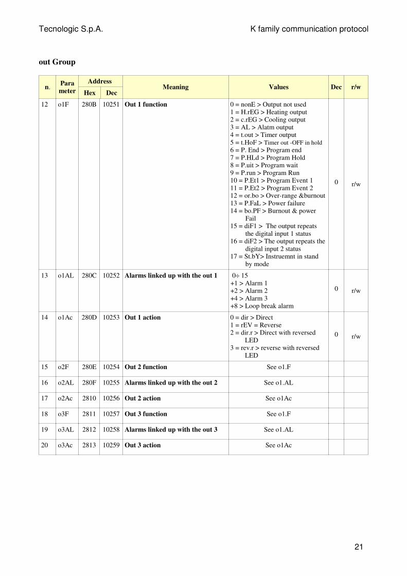
out Group
n.Parameter
Address
Hex DecMeaning Values Dec r/w
12 o1F 280B 10251 Out 1 function 0 = nonE > Output not used1 = H.rEG > Heating output 2 = c.rEG > Cooling output3 = AL > Alatm output4 = t.out > Timer output5 = t.HoF > Timer out -OFF in hold6 = P. End > Program end7 = P.HLd > Program Hold8 = P.uit > Program wait9 = P.run > Program Run10 = P.Et1 > Program Event 111 = P.Et2 > Program Event 212 = or.bo > Over-range &burnout13 = P.FaL > Power failure14 = bo.PF > Burnout & power
Fail15 = diF1 > The output repeats
the digital input 1 status16 = diF2 > The output repeats the
digital input 2 status17 = St.bY> Instruemnt in stand
by mode
0 r/w
13 o1AL 280C 10252 Alarms linked up with the out 1 0÷ 15+1 > Alarm 1+2 > Alarm 2+4 > Alarm 3+8 > Loop break alarm
0 r/w
14 o1Ac 280D 10253 Out 1 action 0 = dir > Direct1 = rEV = Reverse2 = dir.r > Direct with reversed
LED3 = rev.r > reverse with reversed
LED
0 r/w
15 o2F 280E 10254 Out 2 function See o1.F
16 o2AL 280F 10255 Alarms linked up with the out 2 See o1.AL
17 o2Ac 2810 10256 Out 2 action See o1Ac
18 o3F 2811 10257 Out 3 function See o1.F
19 o3AL 2812 10258 Alarms linked up with the out 3 See o1.AL
20 o3Ac 2813 10259 Out 3 action See o1Ac
21
Tecnologic S.p.A. K family communication protocol
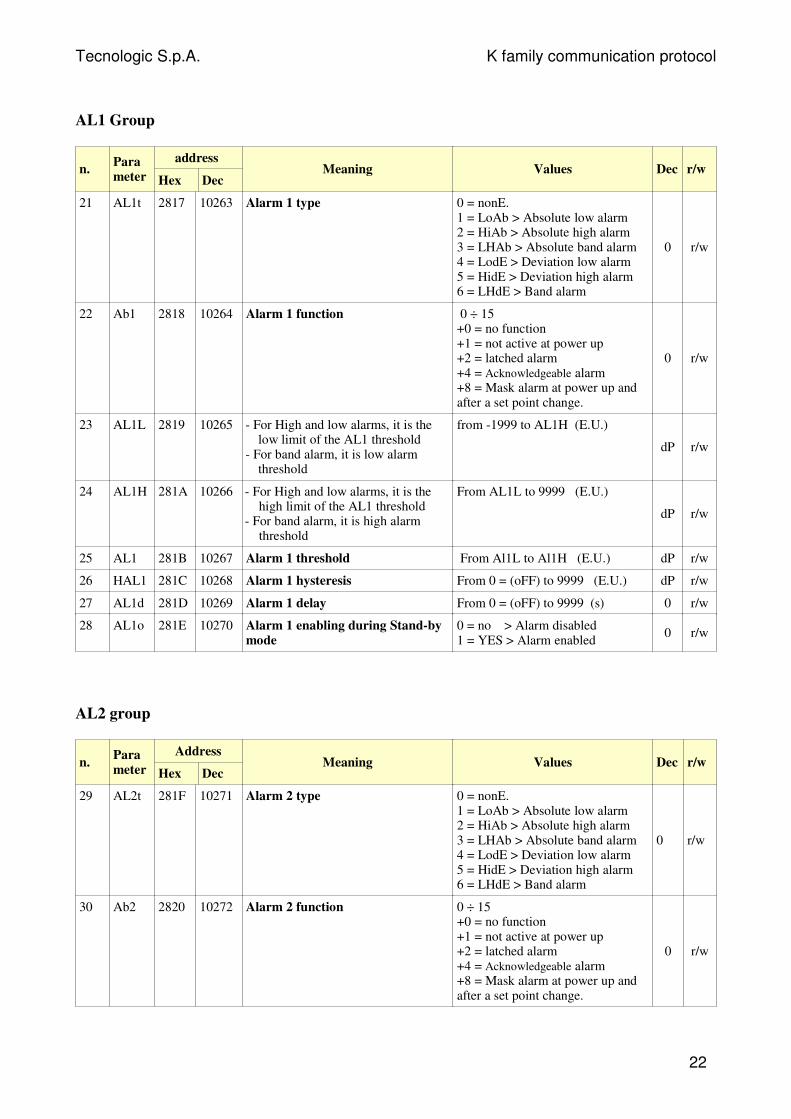
AL1 Group
n.Parameter
address
Hex DecMeaning Values Dec r/w
21 AL1t 2817 10263 Alarm 1 type 0 = nonE.1 = LoAb > Absolute low alarm2 = HiAb > Absolute high alarm3 = LHAb > Absolute band alarm4 = LodE > Deviation low alarm5 = HidE > Deviation high alarm6 = LHdE > Band alarm
0 r/w
22 Ab1 2818 10264 Alarm 1 function 0 ÷ 15+0 = no function+1 = not active at power up+2 = latched alarm+4 = Acknowledgeable alarm+8 = Mask alarm at power up andafter a set point change.
0 r/w
23 AL1L 2819 10265 - For High and low alarms, it is thelow limit of the AL1 threshold
- For band alarm, it is low alarmthreshold
from -1999 to AL1H (E.U.)
dP r/w
24 AL1H 281A 10266 - For High and low alarms, it is thehigh limit of the AL1 threshold
- For band alarm, it is high alarmthreshold
From AL1L to 9999 (E.U.)
dP r/w
25 AL1 281B 10267 Alarm 1 threshold From Al1L to Al1H (E.U.) dP r/w
26 HAL1 281C 10268 Alarm 1 hysteresis From 0 = (oFF) to 9999 (E.U.) dP r/w
27 AL1d 281D 10269 Alarm 1 delay From 0 = (oFF) to 9999 (s) 0 r/w
28 AL1o 281E 10270 Alarm 1 enabling during Stand-bymode
0 = no > Alarm disabled 1 = YES > Alarm enabled
0 r/w
AL2 group
n.Parameter
Address
Hex DecMeaning Values Dec r/w
29 AL2t 281F 10271 Alarm 2 type 0 = nonE.1 = LoAb > Absolute low alarm2 = HiAb > Absolute high alarm3 = LHAb > Absolute band alarm4 = LodE > Deviation low alarm5 = HidE > Deviation high alarm6 = LHdE > Band alarm
0 r/w
30 Ab2 2820 10272 Alarm 2 function 0 ÷ 15+0 = no function+1 = not active at power up+2 = latched alarm+4 = Acknowledgeable alarm+8 = Mask alarm at power up andafter a set point change.
0 r/w
22
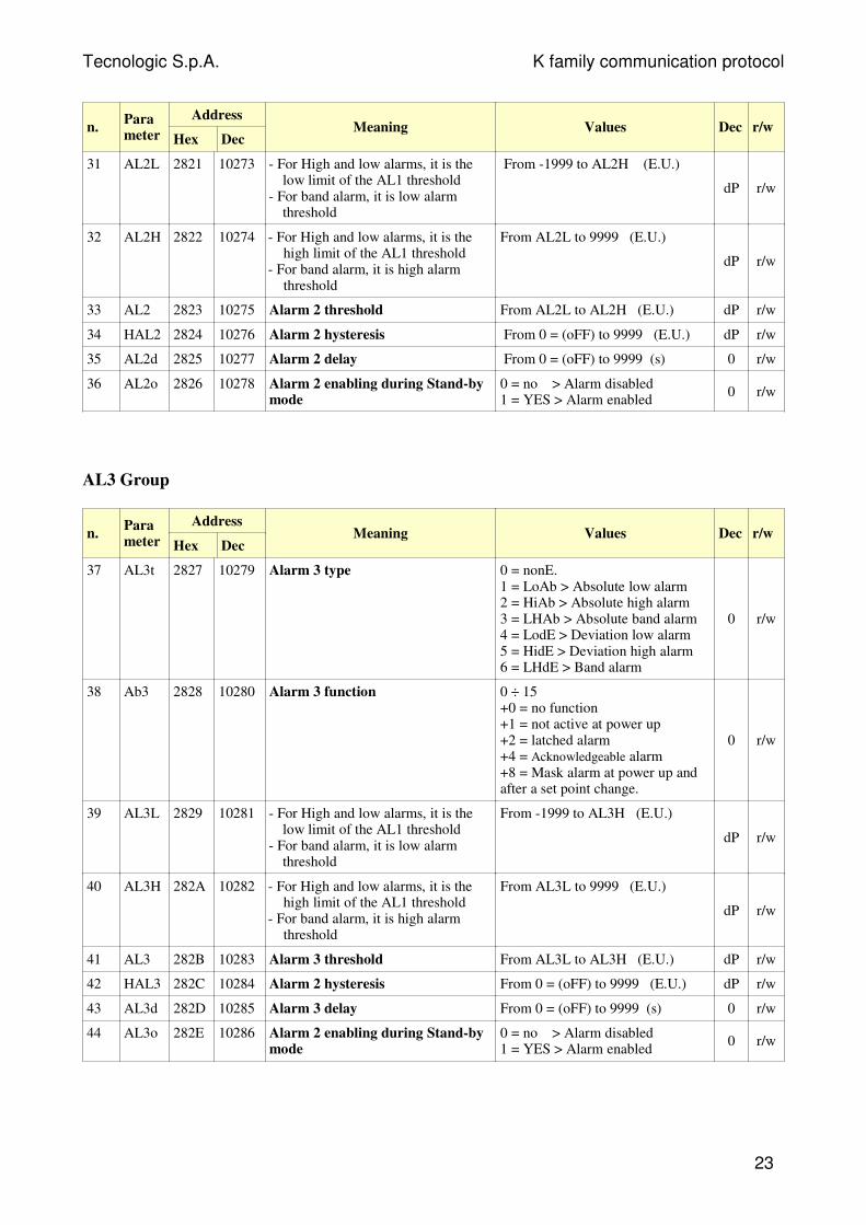
Tecnologic S.p.A. K family communication protocol
n.Parameter
Address
Hex DecMeaning Values Dec r/w
31 AL2L 2821 10273 - For High and low alarms, it is thelow limit of the AL1 threshold
- For band alarm, it is low alarmthreshold
From -1999 to AL2H (E.U.)
dP r/w
32 AL2H 2822 10274 - For High and low alarms, it is thehigh limit of the AL1 threshold
- For band alarm, it is high alarmthreshold
From AL2L to 9999 (E.U.)
dP r/w
33 AL2 2823 10275 Alarm 2 threshold From AL2L to AL2H (E.U.) dP r/w
34 HAL2 2824 10276 Alarm 2 hysteresis From 0 = (oFF) to 9999 (E.U.) dP r/w
35 AL2d 2825 10277 Alarm 2 delay From 0 = (oFF) to 9999 (s) 0 r/w
36 AL2o 2826 10278 Alarm 2 enabling during Stand-bymode
0 = no > Alarm disabled 1 = YES > Alarm enabled
0 r/w
AL3 Group
n.Parameter
Address
Hex DecMeaning Values Dec r/w
37 AL3t 2827 10279 Alarm 3 type 0 = nonE.1 = LoAb > Absolute low alarm2 = HiAb > Absolute high alarm3 = LHAb > Absolute band alarm4 = LodE > Deviation low alarm5 = HidE > Deviation high alarm6 = LHdE > Band alarm
0 r/w
38 Ab3 2828 10280 Alarm 3 function 0 ÷ 15+0 = no function+1 = not active at power up+2 = latched alarm+4 = Acknowledgeable alarm+8 = Mask alarm at power up andafter a set point change.
0 r/w
39 AL3L 2829 10281 - For High and low alarms, it is thelow limit of the AL1 threshold
- For band alarm, it is low alarmthreshold
From -1999 to AL3H (E.U.)
dP r/w
40 AL3H 282A 10282 - For High and low alarms, it is thehigh limit of the AL1 threshold
- For band alarm, it is high alarmthreshold
From AL3L to 9999 (E.U.)
dP r/w
41 AL3 282B 10283 Alarm 3 threshold From AL3L to AL3H (E.U.) dP r/w
42 HAL3 282C 10284 Alarm 2 hysteresis From 0 = (oFF) to 9999 (E.U.) dP r/w
43 AL3d 282D 10285 Alarm 3 delay From 0 = (oFF) to 9999 (s) 0 r/w
44 AL3o 282E 10286 Alarm 2 enabling during Stand-bymode
0 = no > Alarm disabled 1 = YES > Alarm enabled
0 r/w
23
Tecnologic S.p.A. K family communication protocol
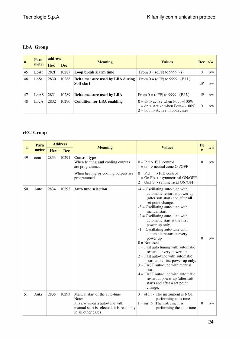
LbA Group
n.Parameter
address
Hex DecMeaning Values Dec r/w
45 LbAt 282F 10287 Loop break alarm time From 0 = (oFF) to 9999 (s) 0 r/w
46 LbSt 2830 10288 Delta measure used by LBA duringSoft start
From 0 = (oFF) to 9999 (E.U.)dP r/w
47 LbAS 2831 10289 Delta measure used by LBA From 0 = (oFF) to 9999 (E.U.) dP r/w
48 LbcA 2832 10290 Condition for LBA enabling 0 = uP > active when Pout =100%1 = dn > Active when Pout= -100%2 = both > Active in both cases
0 r/w
rEG Group
n.Parameter
Address
Hex DecMeaning Values
Dec
r/w
49 cont 2833 10291 Control type When heating and cooling outputsare programmed
0 = Pid > PID control1 = nr > neutral zone On/OFF
0 r/w
When heating or cooling outputs areprogrammed
0 = Pid > PID control1 = On.FA > asymmetrical ON/OFF2 = On.FS > symmetrical ON/OFF
50 Auto 2834 10292 Auto tune selection -4 = Oscillating auto-tune withautomatic restart at power up(after soft start) and after allset point change.
-3 = Oscillating auto-tune withmanual start.
-2 = Oscillating auto-tune withautomatic start at the firstpower up only.
-1 = Oscillating auto-tune withautomatic restart at everypower up
0 = Not used1 = Fast auto tuning with automatic
restart at every power up2 = Fast auto-tune with automatic
start at the first power up only.3 = FAST auto-tune with manual
start4 = FAST auto-tune with automatic
restart at power up (after softstart) and after a set pointchange.
0 r/w
51 Aut.r 2835 10293 Manual start of the auto-tuneNote:it is r/w when a auto-tune withmanual start is selected, it is read onlyin all other cases
0 = oFF > The instrument is NOTperforming auto-tune
1 = on > The instrument isperforming the auto-tune
0 r/w
24
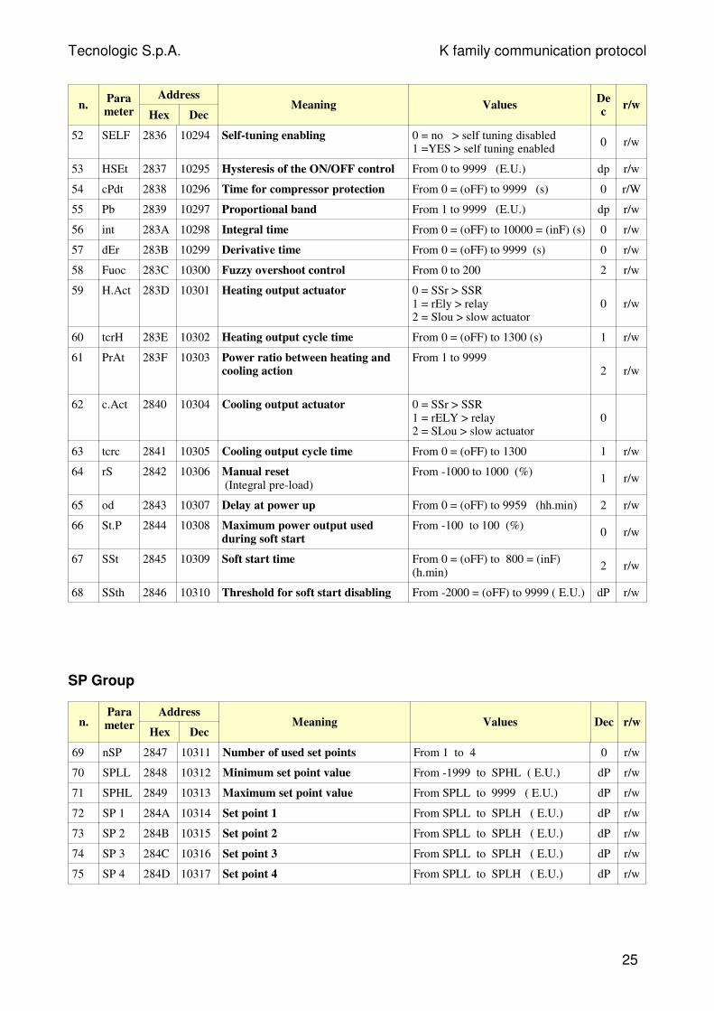
Tecnologic S.p.A. K family communication protocol
n.Parameter
Address
Hex DecMeaning Values
Dec
r/w
52 SELF 2836 10294 Self-tuning enabling 0 = no > self tuning disabled1 =YES > self tuning enabled
0 r/w
53 HSEt 2837 10295 Hysteresis of the ON/OFF control From 0 to 9999 (E.U.) dp r/w
54 cPdt 2838 10296 Time for compressor protection From 0 = (oFF) to 9999 (s) 0 r/W
55 Pb 2839 10297 Proportional band From 1 to 9999 (E.U.) dp r/w
56 int 283A 10298 Integral time From 0 = (oFF) to 10000 = (inF) (s) 0 r/w
57 dEr 283B 10299 Derivative time From 0 = (oFF) to 9999 (s) 0 r/w
58 Fuoc 283C 10300 Fuzzy overshoot control From 0 to 200 2 r/w
59 H.Act 283D 10301 Heating output actuator 0 = SSr > SSR1 = rEly > relay2 = Slou > slow actuator
0 r/w
60 tcrH 283E 10302 Heating output cycle time From 0 = (oFF) to 1300 (s) 1 r/w
61 PrAt 283F 10303 Power ratio between heating andcooling action
From 1 to 99992 r/w
62 c.Act 2840 10304 Cooling output actuator 0 = SSr > SSR1 = rELY > relay2 = SLou > slow actuator
0
63 tcrc 2841 10305 Cooling output cycle time From 0 = (oFF) to 1300 1 r/w
64 rS 2842 10306 Manual reset (Integral pre-load)
From -1000 to 1000 (%)1 r/w
65 od 2843 10307 Delay at power up From 0 = (oFF) to 9959 (hh.min) 2 r/w
66 St.P 2844 10308 Maximum power output usedduring soft start
From -100 to 100 (%)0 r/w
67 SSt 2845 10309 Soft start time From 0 = (oFF) to 800 = (inF)(h.min)
2 r/w
68 SSth 2846 10310 Threshold for soft start disabling From -2000 = (oFF) to 9999 ( E.U.) dP r/w
SP Group
n.Parameter
Address
Hex DecMeaning Values Dec r/w
69 nSP 2847 10311 Number of used set points From 1 to 4 0 r/w
70 SPLL 2848 10312 Minimum set point value From -1999 to SPHL ( E.U.) dP r/w
71 SPHL 2849 10313 Maximum set point value From SPLL to 9999 ( E.U.) dP r/w
72 SP 1 284A 10314 Set point 1 From SPLL to SPLH ( E.U.) dP r/w
73 SP 2 284B 10315 Set point 2 From SPLL to SPLH ( E.U.) dP r/w
74 SP 3 284C 10316 Set point 3 From SPLL to SPLH ( E.U.) dP r/w
75 SP 4 284D 10317 Set point 4 From SPLL to SPLH ( E.U.) dP r/w
25
Tecnologic S.p.A. K family communication protocol
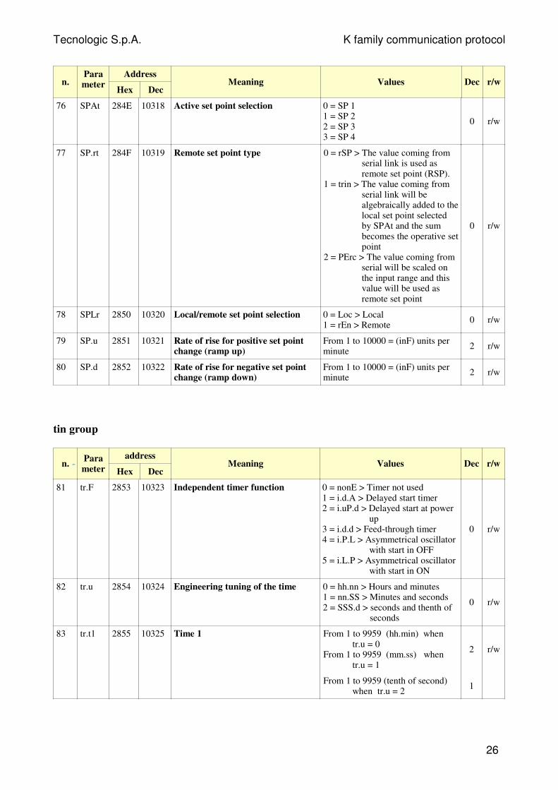
n.Parameter
Address
Hex DecMeaning Values Dec r/w
76 SPAt 284E 10318 Active set point selection 0 = SP 11 = SP 22 = SP 33 = SP 4
0 r/w
77 SP.rt 284F 10319 Remote set point type 0 = rSP > The value coming fromserial link is used asremote set point (RSP).
1 = trin > The value coming fromserial link will bealgebraically added to thelocal set point selectedby SPAt and the sumbecomes the operative setpoint
2 = PErc > The value coming fromserial will be scaled onthe input range and thisvalue will be used asremote set point
0 r/w
78 SPLr 2850 10320 Local/remote set point selection 0 = Loc > Local1 = rEn > Remote
0 r/w
79 SP.u 2851 10321 Rate of rise for positive set pointchange (ramp up)
From 1 to 10000 = (inF) units perminute
2 r/w
80 SP.d 2852 10322 Rate of rise for negative set pointchange (ramp down)
From 1 to 10000 = (inF) units perminute
2 r/w
tin group
n.Parameter
address
Hex DecMeaning Values Dec r/w
81 tr.F 2853 10323 Independent timer function 0 = nonE > Timer not used1 = i.d.A > Delayed start timer2 = i.uP.d > Delayed start at power
up3 = i.d.d > Feed-through timer4 = i.P.L > Asymmetrical oscillator
with start in OFF5 = i.L.P > Asymmetrical oscillator
with start in ON
0 r/w
82 tr.u 2854 10324 Engineering tuning of the time 0 = hh.nn > Hours and minutes1 = nn.SS > Minutes and seconds2 = SSS.d > seconds and thenth of
seconds
0 r/w
83 tr.t1 2855 10325 Time 1 From 1 to 9959 (hh.min) whentr.u = 0
From 1 to 9959 (mm.ss) whentr.u = 1
2 r/w
From 1 to 9959 (tenth of second)when tr.u = 2
1
26
Tecnologic S.p.A. K family communication protocol
n.Parameter
address
Hex DecMeaning Values Dec r/w
84 tr.t2 2856 10326 Time 2 From 0 (oFF) to 9959 (inF)(hh.min) when tr.u = 0
From 0 (oFF) to 9959 (inF)(mm.ss) when tr.u = 1
From 0 (oFF) to 9959 (inF) (tenthof second) when tr.u = 2
2
1
r/w
85 tr.St 2857 10327 Timer status 0 = rES1 = run2 = HoLd
0 r/w
PrG Group
n.Parameter
address
Hex DecMeaning Values Dec r/w
86 Pr.F 2858 10328 Programmer action at power up 0 = nonE > Program not used1 = S.uP.d > Start at power up with
a first step in stand by2 = S.uP.S > Start at power up3 = u.diG > Start at RUN command
detection only4 = U.dG.d > Start at RUN
command detection with afirst step in stand by
0 r/w
87 Pr.u 2859 10329 Engineering unit of the time (soak) 0 = hh.nn > hours and minutes1 = nn.SS > minutes and seconds
0 r/w
88 Pr.E 285A 10330 Instrument behaviour at the End ofthe program execution
0= cnt > continue (the instrumentwill use the set point of the lastsoak until a reset command isdetected)
1 = SPAt > go to the set pointselected by [79] SPAtparameter
2 = St.bY > Go in stand by mode.
0 r/w
89 Pr.Et 285B 10331 Time of the “end program”indication
From 0 = (oFF) to 10000 = (inF)(mm.ss)
2 r/w
90 Pr.S1 285C 10332 Set point of the first soak From SPLL to SPHL (E.U.)-8000 = Program END
dP r/w
91 Pr.G1 285D 10333 Gradient of the first ramp From 1 to 10000 = (inF)(Unit/min) where inF = steptransfer
1 r/w
92 Pr.t1 285E 10334 Time of the first soak From 0 to 9959 2 r/w
93 Pr.b1 285F 10335 Wait band of the first soak From 0 = (oFF) to 9999 (E.U.) 0 r/w
94 Pr.E1 2860 10336 Event of the first group From 00.00 to 11.11 (binary) 2 r/w
95 Pr.S2 2861 10337 Set point of the second soak From SPLL to SPHL (E.U.)-8000 = Program END
dP r/w
96 Pr.G2 2862 10338 Gradient of the second ramp From 1 to 10000 = (inF)(Unit/min) where inF = steptransfer
1 r/w
97 Pr.t2 2863 10339 Time of the second soak From 0 to 9959 2 r/w
27
Tecnologic S.p.A. K family communication protocol
n.Parameter
address
Hex DecMeaning Values Dec r/w
98 Pr.b2 2864 10340 Wait band of the second soak From 0 = (oFF) to 9999 (E.U.) 0 r/w
99 Pr.E2 2865 10341 Event of the second group From 00.00 to 11.11 (binary) 2 r/w
100 Pr.S3 2866 10342 Set point of the third soak From SPLL to SPHL (E.U.)-8000 = Program END
dP r/w
101 Pr.G3 2867 10343 Gradient of the third ramp From 1 to 10000 = (inF)(Unit/min) where inF = steptransfer
1 r/w
102 Pr.t3 2868 10344 Time of the third soak From 0 to 9959 2 r/w
103 Pr.b3 2869 10345 Wait band of the third soak From 0 = (oFF) to 9999 (E.U.) 0 r/w
104 Pr.E3 286A 10346 Events of the third group From 00.00 to 11.11 (binary) 2 r/w
105 Pr.S4 286B 10347 Set point of the fourth soak From SPLL to SPHL (E.U.)-8000 = Program END
dP r/w
106 Pr.G4 286C 10348 Gradient of the fourth ramp From 1 to 10000 = (inF)(Unit/min) where inF = steptransfer
1 r/w
107 Pr.t4 286D 10349 Time of the fourth soak From 0 to 9959 2 r/w
108 Pr.b4 286E 10350 Wait band of the fourth soak From 0 = (oFF) to 9999 (E.U.) 0 r/w
109 Pr.E4 286F 10351 Events of the fourth group From 00.00 to 11.11 (binary) 2 r/w
110 Pr.St 2870 10352 Program status 0 = rES1 = run2 = HoLd
0 r/w
PAn Group
n.Parameter
Address
Hex DecMeaning Values Dec r/w
111 PAS2 2871 10353 Level 2 password: Assistance From 0 = (oFF) to 999 0 r/w
112 PAS3 2872 10354 Level 3 password: Configuration From 0 to 999 0 r/w
113 uSrb 2873 10355 U button function during runtime
0 = nonE > No function1 = tunE > Auto-tune/self-tune
enabling. 2 = oPLo > Manual mode.3 = AAc > Alarm reset4 = ASi > Alarm acknowledge5 = chSP > Sequential set point
selection6 = St.by > Stand by mode7 = Str.t > Timer run/hold/reset8 = P.run > Program run9 = P.rES > Program reset.10 = P.r.H.r > Program run/hold/reset
0 r/w
28
Tecnologic S.p.A. K family communication protocol
n.Parameter
Address
Hex DecMeaning Values Dec r/w
114 diSP 2874 10356 Display management 0= nonE > Standard display 1 = Pou > Power output2 = SPF > Final set point3 = SPo > Operative set point4 = AL1 > Alarm 1 threshold5 = AL2 > Alarm 2 threshold6 = AL3 > Alarm 3 threshold7 = Pr.tu > Increasing time count of
the current soak.8 = Pr.td > Decreasing time count of
the current soak.9 = P.t.tu > Increasing time count of
the total program time.10 = P.t.td > Decreasing time count of
the total program time.11 = ti.uP > Increasing time of the
timer 12 = ti.du > Decreasing time of the
timer 13 = Perc > Percent of the power
output used during soft start.
r/w
115 AdE 2875 10357 Bargraph deviation From 0 = (oFF) to 9999 (E.U.) Dp r/w
116 FiLd 2876 10358 Digital filter on the displayedvalue
From 0 = (oFF) to 99991 r/w
117 DSPu 2877 10359 Status of the instrument atpower up
0 = AS.Pr > Starts in the same way itwas prior to the power down.
1 = Auto > Starts in AUTO mode2 = oP.o > Starts in Manual mode with
a power out equal to 03= StbY > Starts in stand-by mode
0 r/w
118 oPr.E 2878 10360 Operative modes enabling 0 = ALL > All1 = Au.oP > Only Auto and Man.2 = Au.Sb > Only Auto and Stand-by
0 r/w
119 oPEr 2879 10361 Operative mode selection 0 = Auto > Auto1 = oPLo > Manual2 = StbY > stand by
0 r/w
SEr Group
n.Parameter
Address
Hex DecMeaning Values Dec r/w
120 Add 287A 10362 Instrument address From 0 = (oFF) to 254 0 r/w
121 bAud 287B 10363 Baud rate 0 = 1200 baud1 = 2400 baud2 = 9600 baud3 = 19200 baud4 = 38400 baud
0 r/w
122 tr.SP 287C 10364 Remote set point retransmission 0 = not used1 = Operative Set point2 = Control output percent
0 r/w
29
Tecnologic S.p.A. K family communication protocol
con Group (Wattmeter)
n.Parameter
Address
Hex DecMeaning Values Dec r/w
123 co.tY 287D 10365 Measurement type 0 = Off- not used1 = Istantaneous power (KW)2 = Power consumption (KW/h)3 = Power consumption duringprogram run.4 = Worked days5 = Worked hours
0 r/w
124 UOLt 287E 10366 Nominal voltage From 1 to 999 (Volt) 0 r/w
125 cur 287F 10367 Nominal current From 1 to 9999 (A) 0 r/w
126 H.Job 2880 10368 Threshold of the workeddays/hours
From 0 = (oFF) to 9999 0 r/w
cAL Group
n.Parameter
Address
Hex DecMeaning Values
Dec
r/w
127 A.L.P 2881 10369 Adjust low point From -1999 to A.H.P-10(E.U.)
dP r/w
128 A.L.o 2882 10370 Adjust low offset From -300 to 300 ( E.U.) dP r/w
129 A.H.P 2883 10371 Adjust high point From A.L.P+10 to 9999(E.U.)
dP r/w
130 A.H.o 2884 10372 Adjust high offset From -300 to 300 ( E.U.) dP r/w
SYS Group (Not visible parameters)
n.Parameter
Address
Hex DecMeaning Values Dec r/w
131 ES.L 2885 10373 Low measure value for “measuringerror” generation
From -1999 to ES.H ( E.U.)dP r/w
132 ES.H 2886 10374 High measure value for “measuringerror” generation
From ES.L to 9999 ( E.U.)dP r/w
133 At.L 2887 10375 Percent of the set point used to stopthe soft start and start the auto-tune.
From -20 to 100 (%)0 r/w
134 c.Pb 2888 10376 Proportional band adjustment From 1 to 1000 1 r/w
135 c.int 2889 10377 Integral time adjustment From 1 to 1000 1 r/w
136 c.dEr 288A 10378 Derivative time adjustment From 1 to 1000 1 r/w
137 c.tcr 288B 10379 Tcr adjustment From 1 to 1000 1 r/w
30

Tecnologic S.p.A. K family communication protocol
n.Parameter
Address
Hex DecMeaning Values Dec r/w
138 oS.Pb 288C 10380 Proportional band for Oscillatormethod (autotune)
From 1 to 10001 r/w
139 Osti 288D 10381 Output span From 1 to 1000 1 r/w
140 A 288E 10382 Span of the calculated oscillation(autotune)
From 0 to 99990 r/w
141 t 288F 10383 Oscillation period (auto-tune) From 0 to 9999 0 r/w
142 tAu 2890 10384 Time constant for auto-tunecalculation
From -1999 to 99990 r/w
31
Tecnologic S.p.A. K family communication protocol
5.1.1 Identification code zone
This zone provides only informations for identifying model, order code and softwarerelease of the K series instrument.
Starting from the address 0800H it’s possibile to read the instrument name (TLK41, etc)and from the address 0x80A (up to 0x818) it’s possibile tro read the instrument sales code(starting from 2.2 version)
6 Performance
After receiving a valid request the instrument prepares the reply, then sends it back to themaster station according following specifications:
• a minimum time is granted greater or equal 3 characters time (depending onadopted baud rate, allowing line direction reversal)
• the reply is ready to be transmitted in less then 20 ms except in case 3;
A 20 ms silence on the line is necessary to recover from abnormal contitions or erroneousmessages; this means that a time less than 20 ms is allowed between any two charactersin the same message.
NOTE VERY WELL: It’s now possible to write up to 16 words at the same time.
32
Tecnologic S.p.A. K family communication protocol
Tecnologic S.p.A.
Via Indipendenza, 56
27029 Vigevano (PV) Italia
Tel. ++39/0381/69871
Fax ++39/0381/698730
e-mail : [email protected]
All rights reserved. No parts of this publication may be reproduced, in any form, without TecnologicS.p.A. written permission.Every care has been taken preparing this manual; the document has been carefully reviewed fortechnical accuracy. In the event that technical or typographical errors exist Tecnologic S.p.A.reserves the right to make changes without any notice.In no event shall Tecnologic S.p.A. be liable for any damages arising out of or related to thisdocument or the information contained in it.If errors are suspected, please contact Tecnologic S.p.A. at the above address.
33
S.p.A.