Internet Protocol - PUCPR
19
PUCPR 2014 Internet Protocol ClassFul and Classless Address Model Edgard Jamhour E NGLISH S EMESTER
Transcript of Internet Protocol - PUCPR
PUCPR
2014
Internet Protocol CCllaassssFFuull aanndd CCllaasssslleessss AAddddrreessss MMooddeell
Edgard Jamhour
E N G L I S H S E M E S T E R
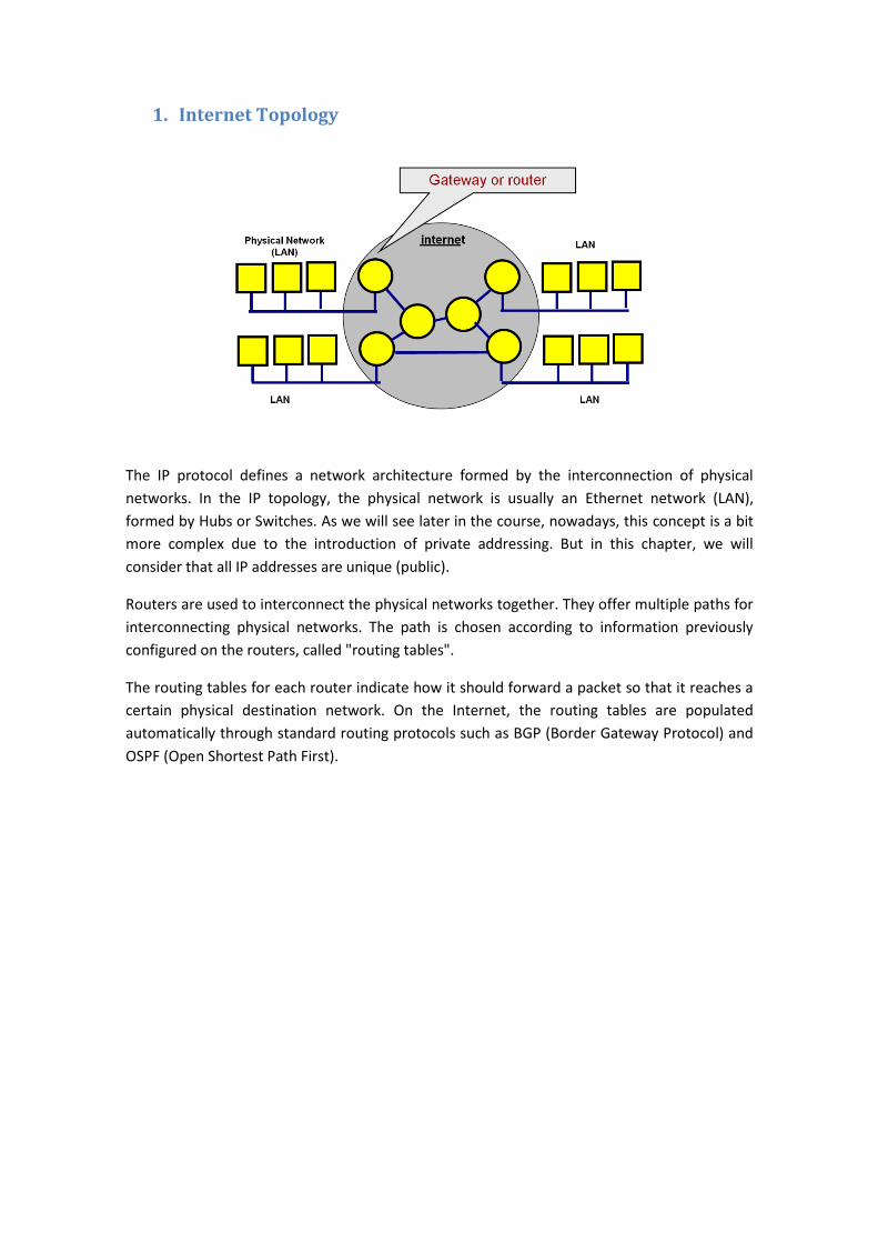
1. Internet Topology
The IP protocol defines a network architecture formed by the interconnection of physical
networks. In the IP topology, the physical network is usually an Ethernet network (LAN),
formed by Hubs or Switches. As we will see later in the course, nowadays, this concept is a bit
more complex due to the introduction of private addressing. But in this chapter, we will
consider that all IP addresses are unique (public).
Routers are used to interconnect the physical networks together. They offer multiple paths for
interconnecting physical networks. The path is chosen according to information previously
configured on the routers, called "routing tables".
The routing tables for each router indicate how it should forward a packet so that it reaches a
certain physical destination network. On the Internet, the routing tables are populated
automatically through standard routing protocols such as BGP (Border Gateway Protocol) and
OSPF (Open Shortest Path First).
2. Dotted Decimal Notation
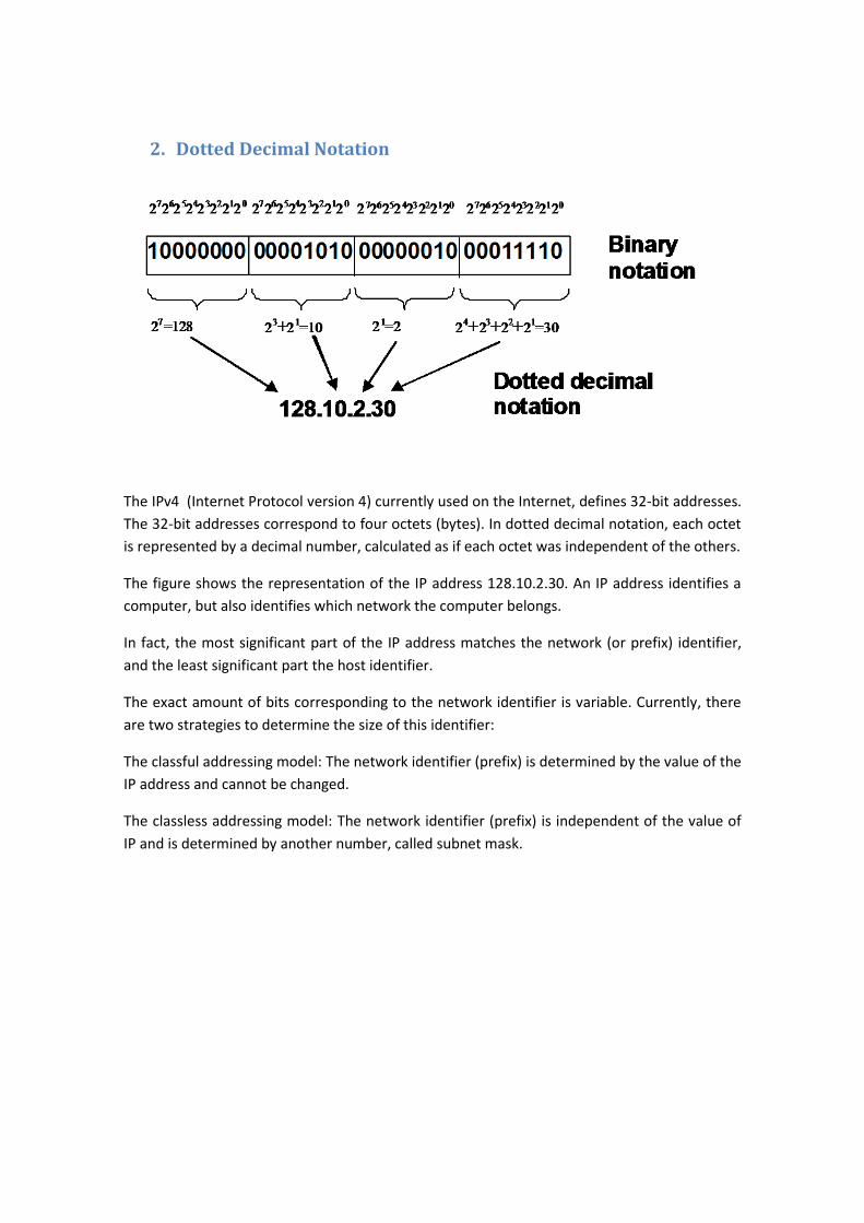
The IPv4 (Internet Protocol version 4) currently used on the Internet, defines 32-bit addresses.
The 32-bit addresses correspond to four octets (bytes). In dotted decimal notation, each octet
is represented by a decimal number, calculated as if each octet was independent of the others.
The figure shows the representation of the IP address 128.10.2.30. An IP address identifies a
computer, but also identifies which network the computer belongs.
In fact, the most significant part of the IP address matches the network (or prefix) identifier,
and the least significant part the host identifier.
The exact amount of bits corresponding to the network identifier is variable. Currently, there
are two strategies to determine the size of this identifier:
The classful addressing model: The network identifier (prefix) is determined by the value of the
IP address and cannot be changed.
The classless addressing model: The network identifier (prefix) is independent of the value of
IP and is determined by another number, called subnet mask.
3. IP Addresses
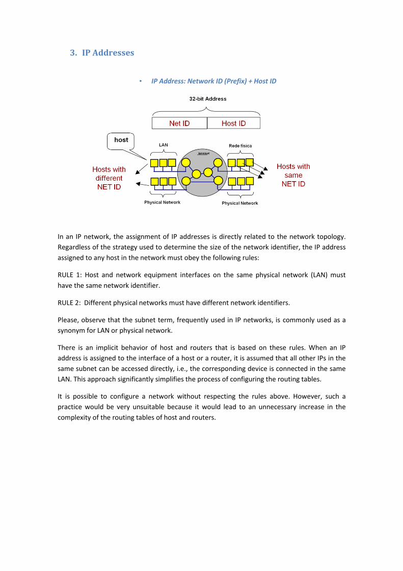
• IP Address: Network ID (Prefix) + Host ID
In an IP network, the assignment of IP addresses is directly related to the network topology.
Regardless of the strategy used to determine the size of the network identifier, the IP address
assigned to any host in the network must obey the following rules:
RULE 1: Host and network equipment interfaces on the same physical network (LAN) must
have the same network identifier.
RULE 2: Different physical networks must have different network identifiers.
Please, observe that the subnet term, frequently used in IP networks, is commonly used as a
synonym for LAN or physical network.
There is an implicit behavior of host and routers that is based on these rules. When an IP
address is assigned to the interface of a host or a router, it is assumed that all other IPs in the
same subnet can be accessed directly, i.e., the corresponding device is connected in the same
LAN. This approach significantly simplifies the process of configuring the routing tables.
It is possible to configure a network without respecting the rules above. However, such a
practice would be very unsuitable because it would lead to an unnecessary increase in the
complexity of the routing tables of host and routers.
4. Classful IP Addressing (The OLD METHOD)
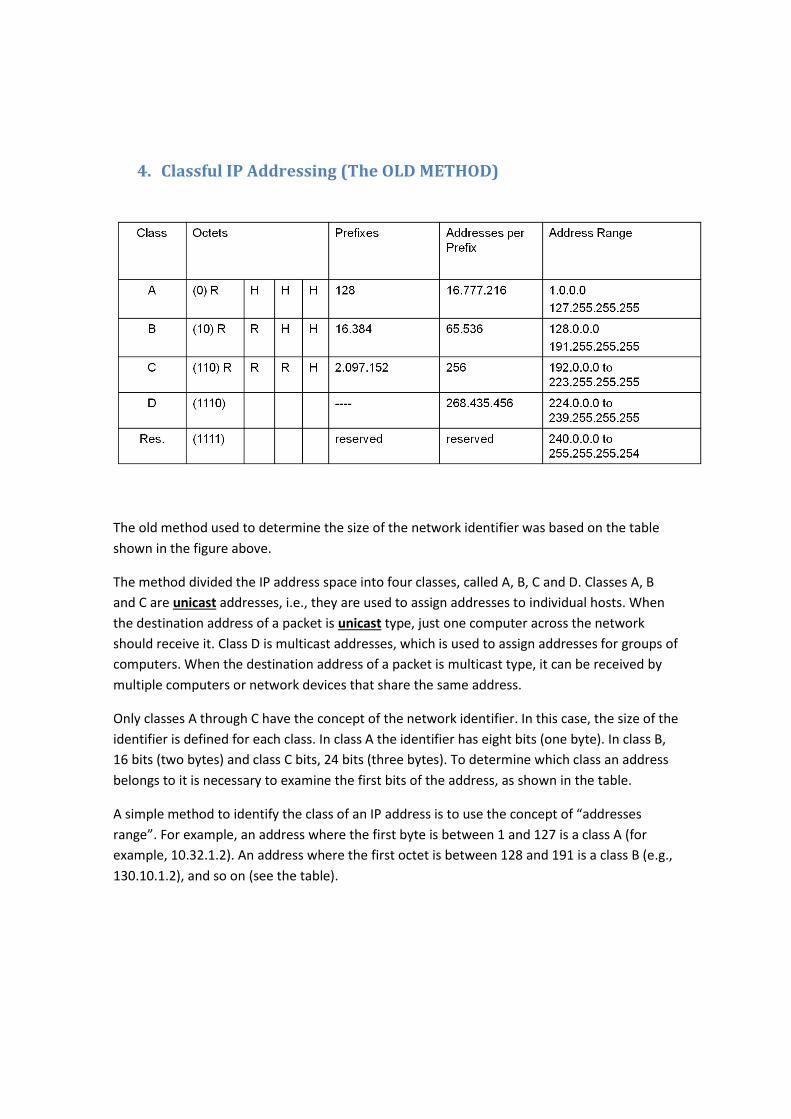
The old method used to determine the size of the network identifier was based on the table
shown in the figure above.
The method divided the IP address space into four classes, called A, B, C and D. Classes A, B
and C are unicast addresses, i.e., they are used to assign addresses to individual hosts. When
the destination address of a packet is unicast type, just one computer across the network
should receive it. Class D is multicast addresses, which is used to assign addresses for groups of
computers. When the destination address of a packet is multicast type, it can be received by
multiple computers or network devices that share the same address.
Only classes A through C have the concept of the network identifier. In this case, the size of the
identifier is defined for each class. In class A the identifier has eight bits (one byte). In class B,
16 bits (two bytes) and class C bits, 24 bits (three bytes). To determine which class an address
belongs to it is necessary to examine the first bits of the address, as shown in the table.
A simple method to identify the class of an IP address is to use the concept of “addresses
range”. For example, an address where the first byte is between 1 and 127 is a class A (for
example, 10.32.1.2). An address where the first octet is between 128 and 191 is a class B (e.g.,
130.10.1.2), and so on (see the table).
5. Prefix Size Interpretation
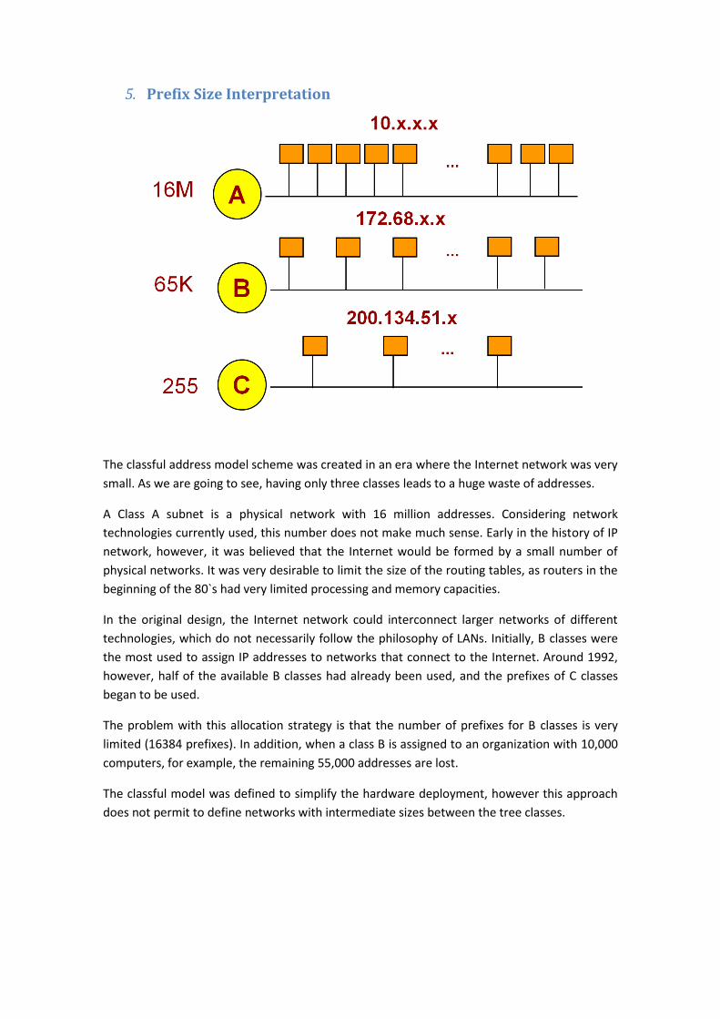
The classful address model scheme was created in an era where the Internet network was very
small. As we are going to see, having only three classes leads to a huge waste of addresses.
A Class A subnet is a physical network with 16 million addresses. Considering network
technologies currently used, this number does not make much sense. Early in the history of IP
network, however, it was believed that the Internet would be formed by a small number of
physical networks. It was very desirable to limit the size of the routing tables, as routers in the
beginning of the 80`s had very limited processing and memory capacities.
In the original design, the Internet network could interconnect larger networks of different
technologies, which do not necessarily follow the philosophy of LANs. Initially, B classes were
the most used to assign IP addresses to networks that connect to the Internet. Around 1992,
however, half of the available B classes had already been used, and the prefixes of C classes
began to be used.
The problem with this allocation strategy is that the number of prefixes for B classes is very
limited (16384 prefixes). In addition, when a class B is assigned to an organization with 10,000
computers, for example, the remaining 55,000 addresses are lost.
The classful model was defined to simplify the hardware deployment, however this approach
does not permit to define networks with intermediate sizes between the tree classes.
6. Address Assignment
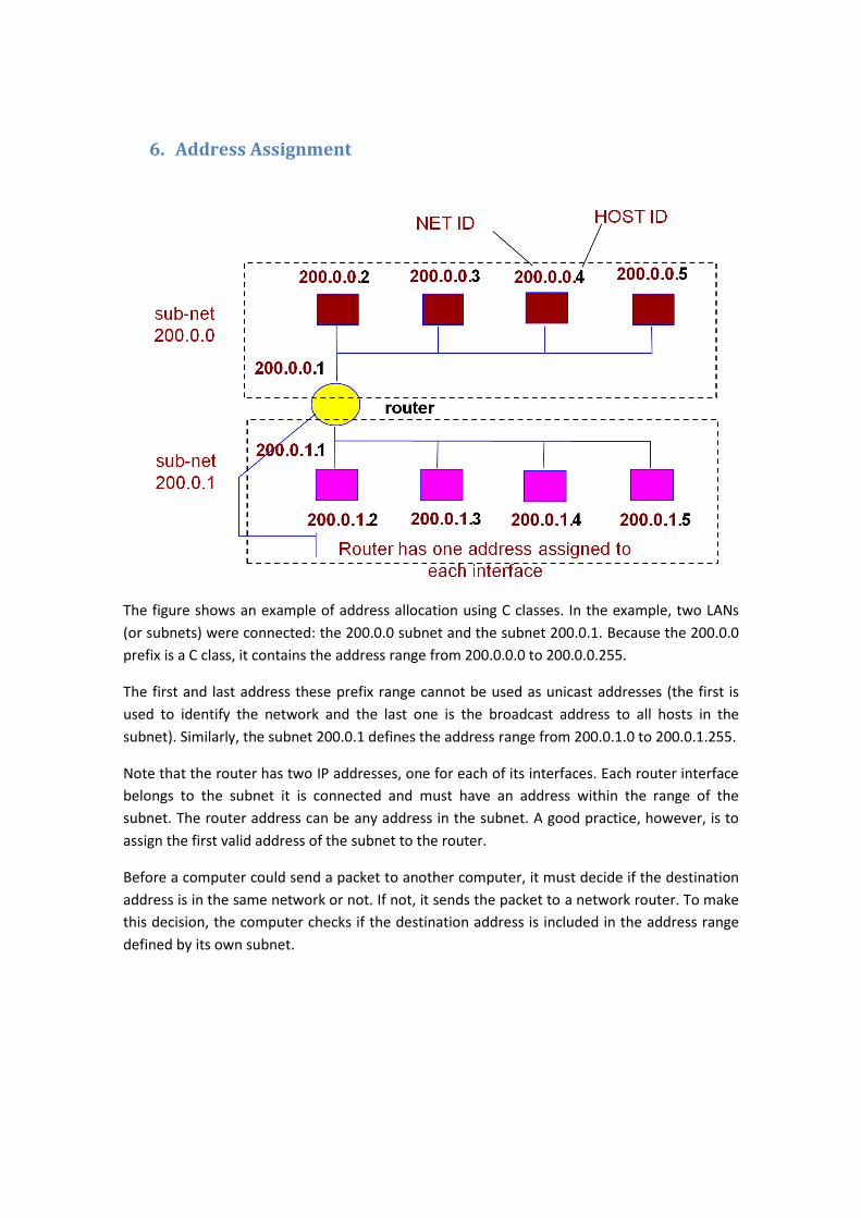
The figure shows an example of address allocation using C classes. In the example, two LANs
(or subnets) were connected: the 200.0.0 subnet and the subnet 200.0.1. Because the 200.0.0
prefix is a C class, it contains the address range from 200.0.0.0 to 200.0.0.255.
The first and last address these prefix range cannot be used as unicast addresses (the first is
used to identify the network and the last one is the broadcast address to all hosts in the
subnet). Similarly, the subnet 200.0.1 defines the address range from 200.0.1.0 to 200.0.1.255.
Note that the router has two IP addresses, one for each of its interfaces. Each router interface
belongs to the subnet it is connected and must have an address within the range of the
subnet. The router address can be any address in the subnet. A good practice, however, is to
assign the first valid address of the subnet to the router.
Before a computer could send a packet to another computer, it must decide if the destination
address is in the same network or not. If not, it sends the packet to a network router. To make
this decision, the computer checks if the destination address is included in the address range
defined by its own subnet.
7. Limitations of the Classful Address Model
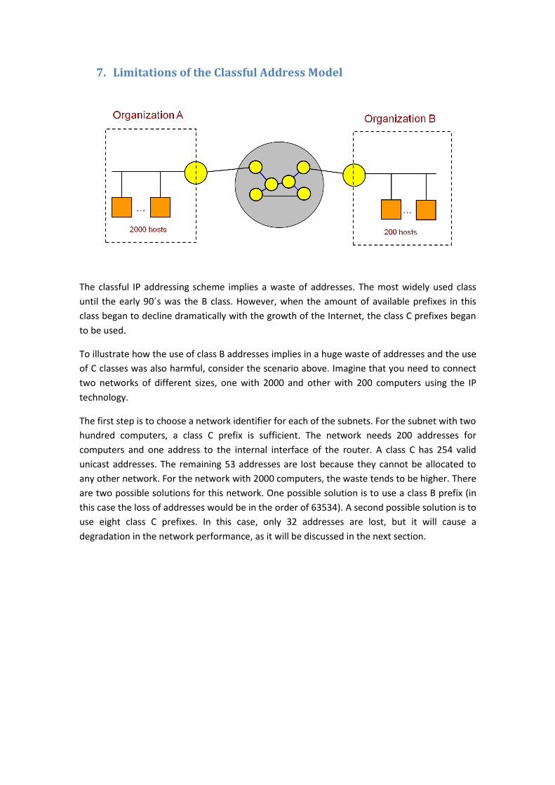
The classful IP addressing scheme implies a waste of addresses. The most widely used class
until the early 90´s was the B class. However, when the amount of available prefixes in this
class began to decline dramatically with the growth of the Internet, the class C prefixes began
to be used.
To illustrate how the use of class B addresses implies in a huge waste of addresses and the use
of C classes was also harmful, consider the scenario above. Imagine that you need to connect
two networks of different sizes, one with 2000 and other with 200 computers using the IP
technology.
The first step is to choose a network identifier for each of the subnets. For the subnet with two
hundred computers, a class C prefix is sufficient. The network needs 200 addresses for
computers and one address to the internal interface of the router. A class C has 254 valid
unicast addresses. The remaining 53 addresses are lost because they cannot be allocated to
any other network. For the network with 2000 computers, the waste tends to be higher. There
are two possible solutions for this network. One possible solution is to use a class B prefix (in
this case the loss of addresses would be in the order of 63534). A second possible solution is to
use eight class C prefixes. In this case, only 32 addresses are lost, but it will cause a
degradation in the network performance, as it will be discussed in the next section.
8. Number of Prefixes and Network Topology
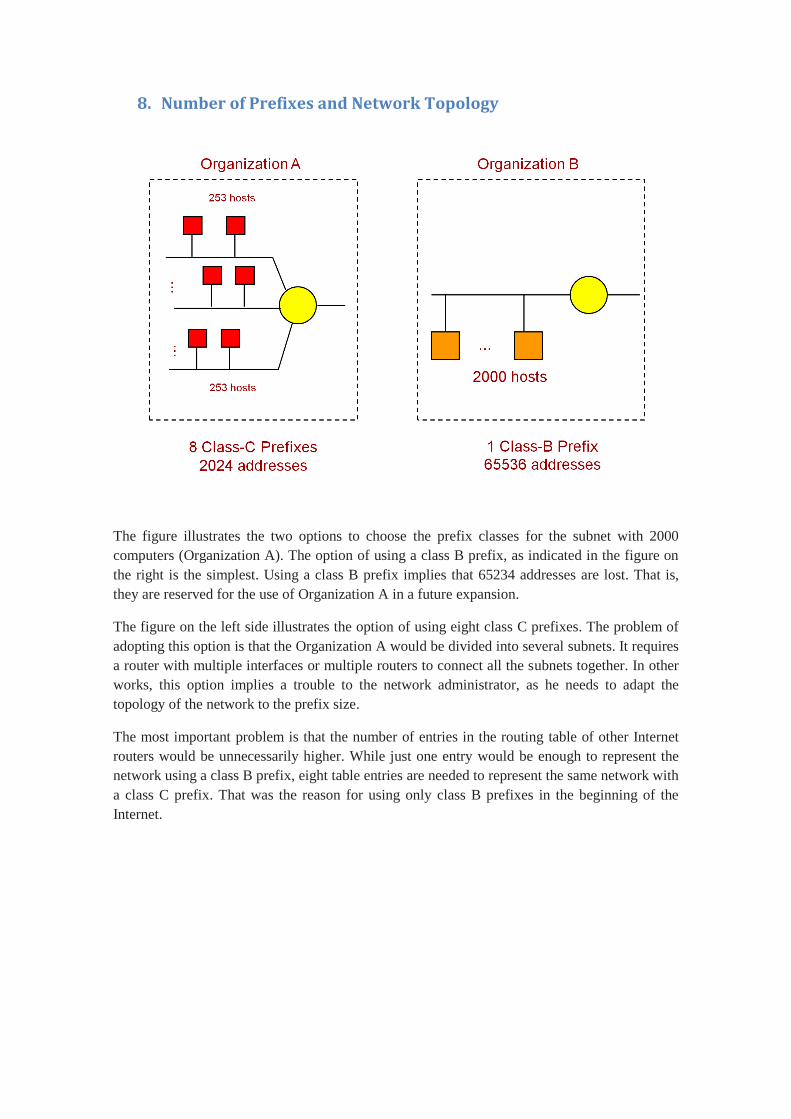
The figure illustrates the two options to choose the prefix classes for the subnet with 2000
computers (Organization A). The option of using a class B prefix, as indicated in the figure on
the right is the simplest. Using a class B prefix implies that 65234 addresses are lost. That is,
they are reserved for the use of Organization A in a future expansion.
The figure on the left side illustrates the option of using eight class C prefixes. The problem of
adopting this option is that the Organization A would be divided into several subnets. It requires
a router with multiple interfaces or multiple routers to connect all the subnets together. In other
works, this option implies a trouble to the network administrator, as he needs to adapt the
topology of the network to the prefix size.
The most important problem is that the number of entries in the routing table of other Internet
routers would be unnecessarily higher. While just one entry would be enough to represent the
network using a class B prefix, eight table entries are needed to represent the same network with
a class C prefix. That was the reason for using only class B prefixes in the beginning of the
Internet.
9. Classless IP Addressing
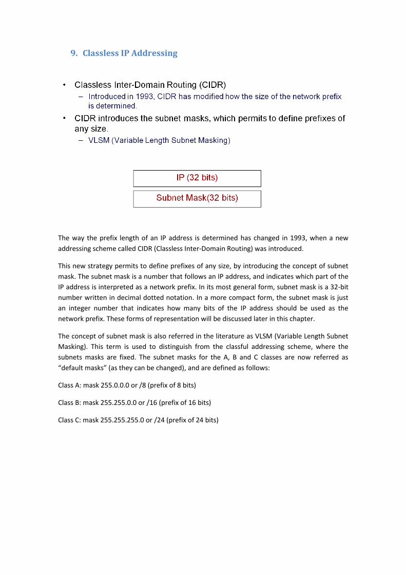
The way the prefix length of an IP address is determined has changed in 1993, when a new
addressing scheme called CIDR (Classless Inter-Domain Routing) was introduced.
This new strategy permits to define prefixes of any size, by introducing the concept of subnet
mask. The subnet mask is a number that follows an IP address, and indicates which part of the
IP address is interpreted as a network prefix. In its most general form, subnet mask is a 32-bit
number written in decimal dotted notation. In a more compact form, the subnet mask is just
an integer number that indicates how many bits of the IP address should be used as the
network prefix. These forms of representation will be discussed later in this chapter.
The concept of subnet mask is also referred in the literature as VLSM (Variable Length Subnet
Masking). This term is used to distinguish from the classful addressing scheme, where the
subnets masks are fixed. The subnet masks for the A, B and C classes are now referred as
“default masks” (as they can be changed), and are defined as follows:
Class A: mask 255.0.0.0 or /8 (prefix of 8 bits)
Class B: mask 255.255.0.0 or /16 (prefix of 16 bits)
Class C: mask 255.255.255.0 or /24 (prefix of 24 bits)
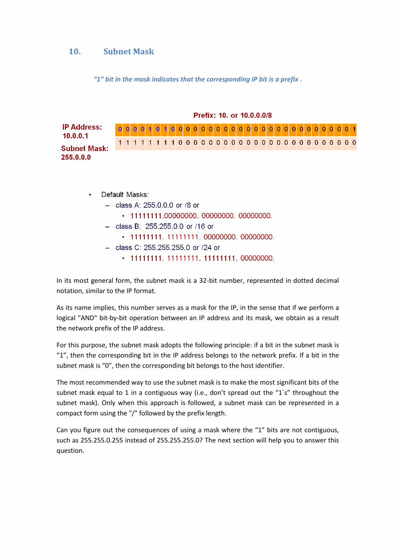
10. Subnet Mask
“1” bit in the mask indicates that the corresponding IP bit is a prefix .
In its most general form, the subnet mask is a 32-bit number, represented in dotted decimal
notation, similar to the IP format.
As its name implies, this number serves as a mask for the IP, in the sense that if we perform a
logical "AND" bit-by-bit operation between an IP address and its mask, we obtain as a result
the network prefix of the IP address.
For this purpose, the subnet mask adopts the following principle: if a bit in the subnet mask is
“1”, then the corresponding bit in the IP address belongs to the network prefix. If a bit in the
subnet mask is “0”, then the corresponding bit belongs to the host identifier.
The most recommended way to use the subnet mask is to make the most significant bits of the
subnet mask equal to 1 in a contiguous way (i.e., don’t spread out the “1´s” throughout the
subnet mask). Only when this approach is followed, a subnet mask can be represented in a
compact form using the "/" followed by the prefix length.
Can you figure out the consequences of using a mask where the “1” bits are not contiguous,
such as 255.255.0.255 instead of 255.255.255.0? The next section will help you to answer this
question.
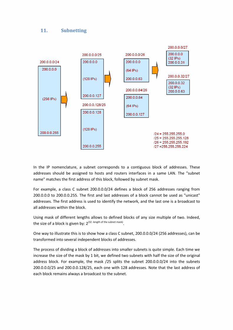
11. Subnetting
In the IP nomenclature, a subnet corresponds to a contiguous block of addresses. These
addresses should be assigned to hosts and routers interfaces in a same LAN. The "subnet
name" matches the first address of this block, followed by subnet mask.
For example, a class C subnet 200.0.0.0/24 defines a block of 256 addresses ranging from
200.0.0.0 to 200.0.0.255. The first and last addresses of a block cannot be used as "unicast"
addresses. The first address is used to identify the network, and the last one is a broadcast to
all addresses within the block.
Using mask of different lengths allows to defined blocks of any size multiple of two. Indeed,
the size of a block is given by: 2(32 -length of the subnet mask).
One way to illustrate this is to show how a class C subnet, 200.0.0.0/24 (256 addresses), can be
transformed into several independent blocks of addresses.
The process of dividing a block of addresses into smaller subnets is quite simple. Each time we
increase the size of the mask by 1 bit, we defined two subnets with half the size of the original
address block. For example, the mask /25 splits the subnet 200.0.0.0/24 into the subnets
200.0.0.0/25 and 200.0.0.128/25, each one with 128 addresses. Note that the last address of
each block remains always a broadcast to the subnet.
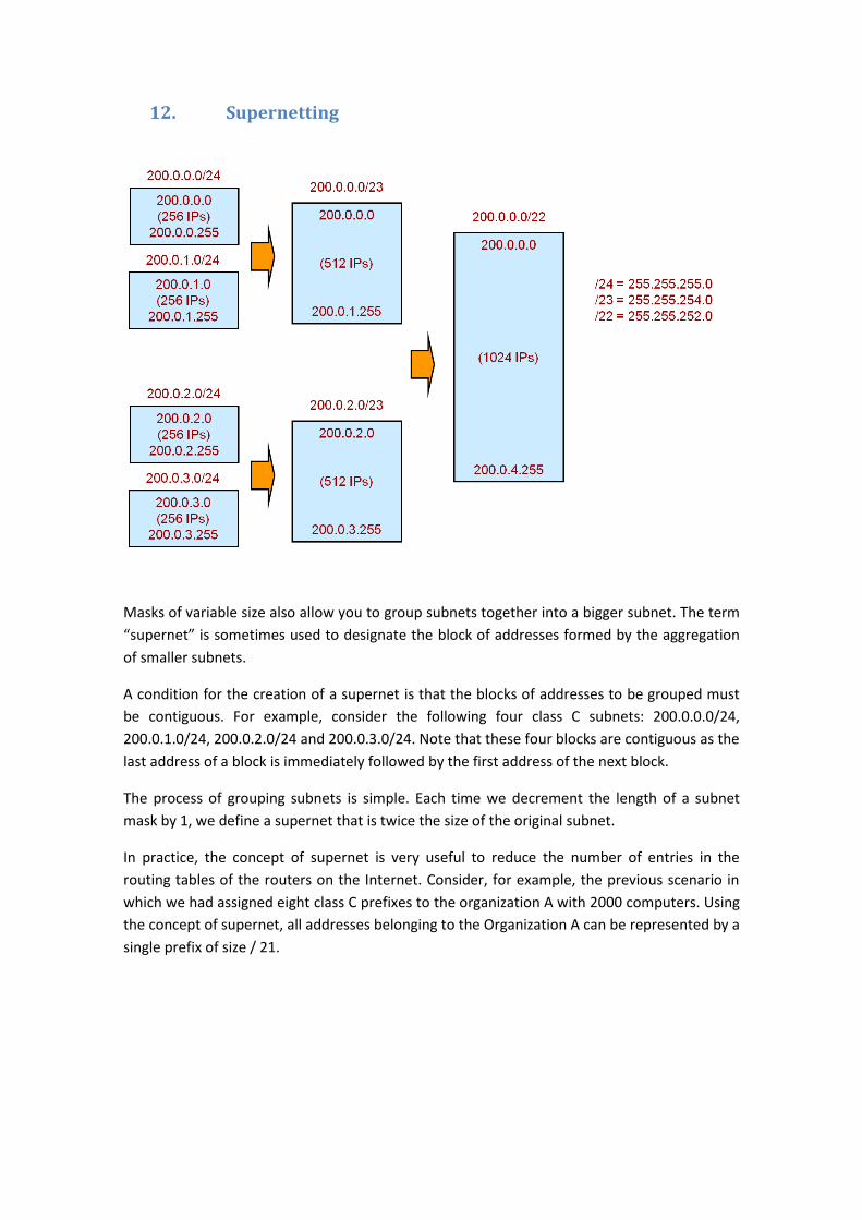
12. Supernetting
Masks of variable size also allow you to group subnets together into a bigger subnet. The term
“supernet” is sometimes used to designate the block of addresses formed by the aggregation
of smaller subnets.
A condition for the creation of a supernet is that the blocks of addresses to be grouped must
be contiguous. For example, consider the following four class C subnets: 200.0.0.0/24,
200.0.1.0/24, 200.0.2.0/24 and 200.0.3.0/24. Note that these four blocks are contiguous as the
last address of a block is immediately followed by the first address of the next block.
The process of grouping subnets is simple. Each time we decrement the length of a subnet
mask by 1, we define a supernet that is twice the size of the original subnet.
In practice, the concept of supernet is very useful to reduce the number of entries in the
routing tables of the routers on the Internet. Consider, for example, the previous scenario in
which we had assigned eight class C prefixes to the organization A with 2000 computers. Using
the concept of supernet, all addresses belonging to the Organization A can be represented by a
single prefix of size / 21.
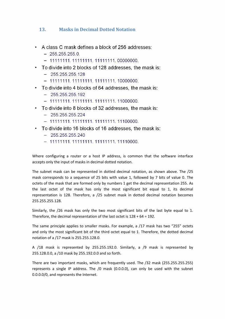
13. Masks in Decimal Dotted Notation
Where configuring a router or a host IP address, is common that the software interface
accepts only the input of masks in decimal dotted notation.
The subnet mask can be represented in dotted decimal notation, as shown above. The /25
mask corresponds to a sequence of 25 bits with value 1, followed by 7 bits of value 0. The
octets of the mask that are formed only by numbers 1 get the decimal representation 255. As
the last octet of the mask has only the most significant bit equal to 1, its decimal
representation is 128. Therefore, a /25 subnet mask in dotted decimal notation becomes
255.255.255.128.
Similarly, the /26 mask has only the two most significant bits of the last byte equal to 1.
Therefore, the decimal representation of the last octet is 128 + 64 = 192.
The same principle applies to smaller masks. For example, a /17 mask has two “255” octets
and only the most significant bit of the third octet equal to 1. Therefore, the dotted decimal
notation of a /17 mask is 255.255.128.0.
A /18 mask is represented by 255.255.192.0. Similarly, a /9 mask is represented by
255.128.0.0, a /10 mask by 255.192.0.0 and so forth.
There are two important masks, which are frequently used. The /32 mask (255.255.255.255)
represents a single IP address. The /0 mask (0.0.0.0), can only be used with the subnet
0.0.0.0/0, and represents the Internet.
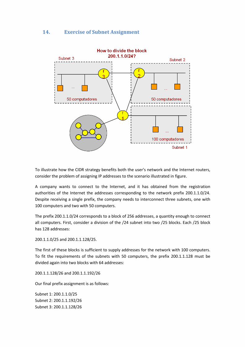
14. Exercise of Subnet Assignment
To illustrate how the CIDR strategy benefits both the user's network and the Internet routers,
consider the problem of assigning IP addresses to the scenario illustrated in figure.
A company wants to connect to the Internet, and it has obtained from the registration
authorities of the Internet the addresses corresponding to the network prefix 200.1.1.0/24.
Despite receiving a single prefix, the company needs to interconnect three subnets, one with
100 computers and two with 50 computers.
The prefix 200.1.1.0/24 corresponds to a block of 256 addresses, a quantity enough to connect
all computers. First, consider a division of the /24 subnet into two /25 blocks. Each /25 block
has 128 addresses:
200.1.1.0/25 and 200.1.1.128/25.
The first of these blocks is sufficient to supply addresses for the network with 100 computers.
To fit the requirements of the subnets with 50 computers, the prefix 200.1.1.128 must be
divided again into two blocks with 64 addresses:
200.1.1.128/26 and 200.1.1.192/26
Our final prefix assignment is as follows:
Subnet 1: 200.1.1.0/25
Subnet 2: 200.1.1.192/26
Subnet 3: 200.1.1.128/26
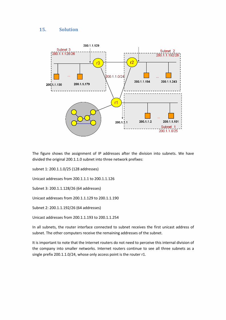
15. Solution
The figure shows the assignment of IP addresses after the division into subnets. We have
divided the original 200.1.1.0 subnet into three network prefixes:
subnet 1: 200.1.1.0/25 (128 addresses)
Unicast addresses from 200.1.1.1 to 200.1.1.126
Subnet 3: 200.1.1.128/26 (64 addresses)
Unicast addresses from 200.1.1.129 to 200.1.1.190
Subnet 2: 200.1.1.192/26 (64 addresses)
Unicast addresses from 200.1.1.193 to 200.1.1.254
In all subnets, the router interface connected to subnet receives the first unicast address of
subnet. The other computers receive the remaining addresses of the subnet.
It is important to note that the Internet routers do not need to perceive this internal division of
the company into smaller networks. Internet routers continue to see all three subnets as a
single prefix 200.1.1.0/24, whose only access point is the router r1.
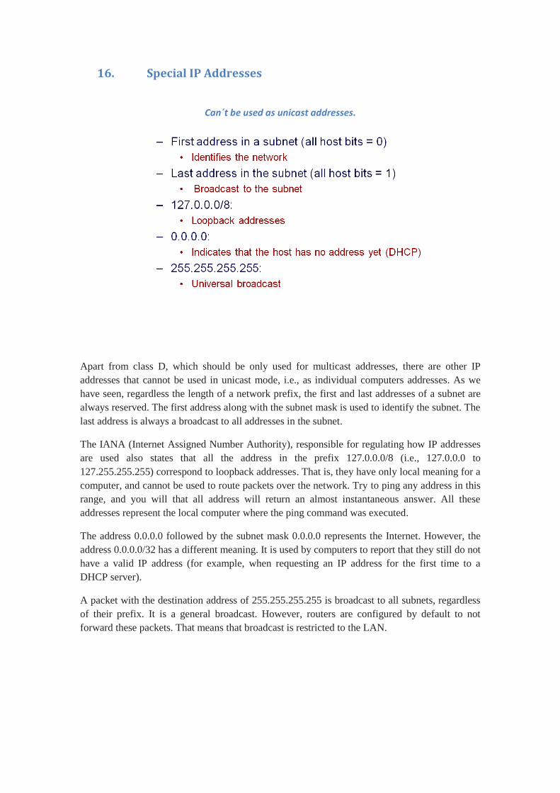
16. Special IP Addresses
Can´t be used as unicast addresses.
Apart from class D, which should be only used for multicast addresses, there are other IP
addresses that cannot be used in unicast mode, i.e., as individual computers addresses. As we
have seen, regardless the length of a network prefix, the first and last addresses of a subnet are
always reserved. The first address along with the subnet mask is used to identify the subnet. The
last address is always a broadcast to all addresses in the subnet.
The IANA (Internet Assigned Number Authority), responsible for regulating how IP addresses
are used also states that all the address in the prefix 127.0.0.0/8 (i.e., 127.0.0.0 to
127.255.255.255) correspond to loopback addresses. That is, they have only local meaning for a
computer, and cannot be used to route packets over the network. Try to ping any address in this
range, and you will that all address will return an almost instantaneous answer. All these
addresses represent the local computer where the ping command was executed.
The address 0.0.0.0 followed by the subnet mask 0.0.0.0 represents the Internet. However, the
address 0.0.0.0/32 has a different meaning. It is used by computers to report that they still do not
have a valid IP address (for example, when requesting an IP address for the first time to a
DHCP server).
A packet with the destination address of 255.255.255.255 is broadcast to all subnets, regardless
of their prefix. It is a general broadcast. However, routers are configured by default to not
forward these packets. That means that broadcast is restricted to the LAN.
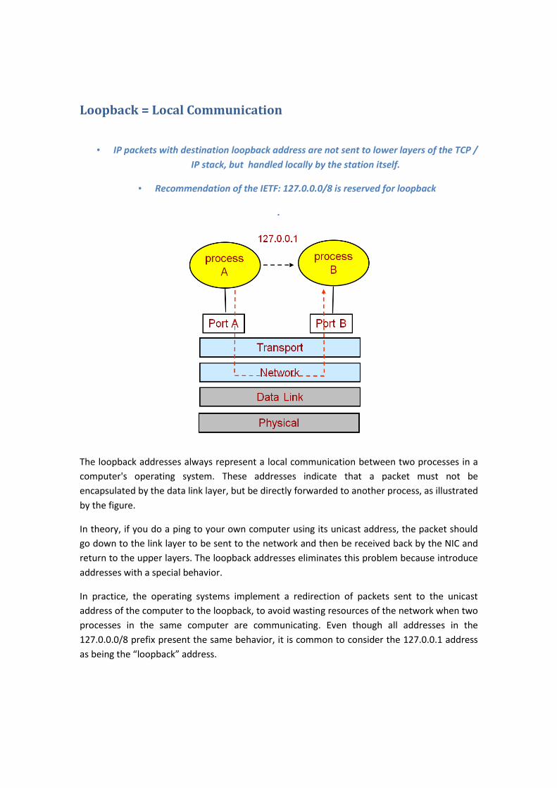
Loopback = Local Communication
• IP packets with destination loopback address are not sent to lower layers of the TCP /
IP stack, but handled locally by the station itself.
• Recommendation of the IETF: 127.0.0.0/8 is reserved for loopback
.
The loopback addresses always represent a local communication between two processes in a
computer's operating system. These addresses indicate that a packet must not be
encapsulated by the data link layer, but be directly forwarded to another process, as illustrated
by the figure.
In theory, if you do a ping to your own computer using its unicast address, the packet should
go down to the link layer to be sent to the network and then be received back by the NIC and
return to the upper layers. The loopback addresses eliminates this problem because introduce
addresses with a special behavior.
In practice, the operating systems implement a redirection of packets sent to the unicast
address of the computer to the loopback, to avoid wasting resources of the network when two
processes in the same computer are communicating. Even though all addresses in the
127.0.0.0/8 prefix present the same behavior, it is common to consider the 127.0.0.1 address
as being the “loopback” address.
17. Conclusion
In this chapter we have seen that the interpretation of IP addresses defined by IANA has
changed in the beginning 90`s.
In the initial model, called “classful addressing scheme”, the length of the network prefix was
determined by the first bits of the IP address itself, and only three sizes of unicast addresses
were available.
In the current model, called classless (also CIDR – Classless Inter Domain Routing), the prefix
length of an IP address is independent of its value, and is determined by another number
called subnet mask.
Presently, an IP address that is not followed by a subnet mask assumes a “default” mask
corresponding to the A, B or C class that it belongs. When the IP address is followed by the
subnet mask, the classes are ignored, as the subnet mask can set any prefix length to any IP
address. The classless addressing scheme is also called VLSM (Variable Length Subnet Mask),
due to this flexibility.