'Milieueffectrapport structuurvisie buisleidingen' PDF document
DNV GL © 2013 SAFER, SMARTER, GREENER DNV GL © 2013
Inleiding Offshore Buisleidingen
Pipeliner Offshore dag
Stichting Pipeliner
Rotterdam, 1 Mei 2015
DNV GL
Jan Spiekhout
DNV GL © 2013
Inhoud
Inleiding
Aanleg
Lassen en NDT
Ontwerp issues
Geohazards
Complexiteit
Normen en standaards
Reparatie
Materiaal aspecten
2
DNV GL © 2013
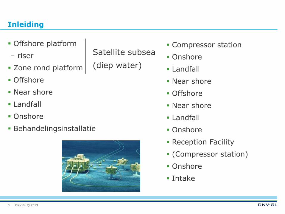
Inleiding
Offshore platform
– riser
Zone rond platform
Offshore
Near shore
Landfall
Onshore
Behandelingsinstallatie
Compressor station
Onshore
Landfall
Near shore
Offshore
Near shore
Landfall
Onshore
Reception Facility
(Compressor station)
Onshore
Intake
3
Satellite subsea
(diep water)
DNV GL © 2013
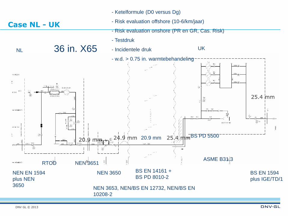
Case NL - UK
NL UK
NEN 3650 BS EN 14161 +
BS PD 8010-2 BS EN 1594
plus IGE/TD/1
NEN 3651 ASME B31.3
BS PD 5500
RTOD
NEN 3653, NEN/BS EN 12732, NEN/BS EN
10208-2
NEN EN 1594
plus NEN
3650
20.9 mm 20.9 mm 24.9 mm 25.4 mm
25.4 mm
36 in. X65
- Ketelformule (D0 versus Dg)
- Risk evaluation offshore (10-6/km/jaar)
- Risk evaluation onshore (PR en GR, Cas. Risk)
- Testdruk
- Incidentele druk
- w.d. > 0.75 in. warmtebehandeling
DNV GL © 2013
Aanleg
Landfall
–Tunnel and shaft
–Bottom tow
–HDD
–Direct Pipe
Near shore – ondiep
Offshore
–Shallow water
–Deep water
5
DNV GL © 2013
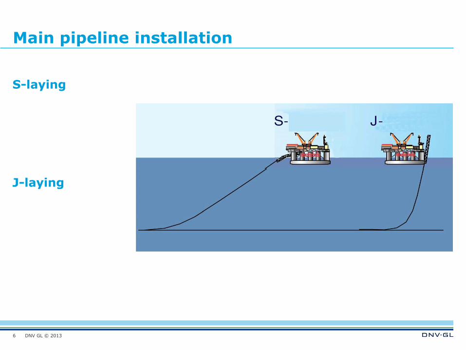
Main pipeline installation
6
S-laying J-laying
DNV GL © 2013
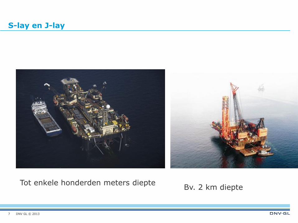
S-lay en J-lay
7
Tot enkele honderden meters diepte Bv. 2 km diepte
DNV GL © 2013
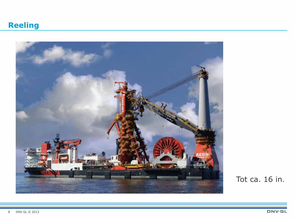
Reeling
8
Tot ca. 16 in.
DNV GL © 2013
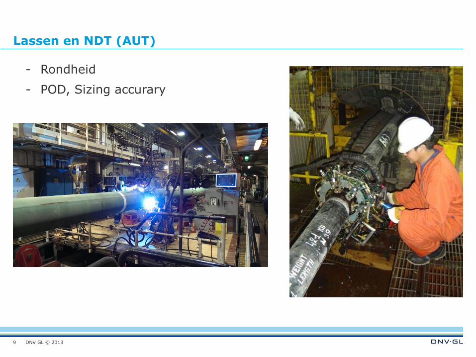
Lassen en NDT (AUT)
9
- Rondheid
- POD, Sizing accurary
DNV GL © 2013
Ontwerp issues offshore buisleidingen
Every detail is important starting with pipe out of roundness limitations
Deviations certainly lead to claims, extra costs and exceeding the project planning
Interfaces are always important
Reduction in engineering, survey and study costs may results in costs overruns with a 10 fold
potential savings cost overrun in construction
Slope (> 30 degr. angle) pipeline route on the slope, pipeline strength aspects (max. diam?)
Stability of sediments on the slope – possibility mud flow etc.
Subsidence zones to be crossed
Sea bottom roughness
Pressure (internal/external)
Free spans
Uplift (currents)
Installation methodology and landfall approach
Linepipe and cable crossings
Seabed intervention and diverless hot-tap and repair technology
10
DNV GL © 2013
G R O U P
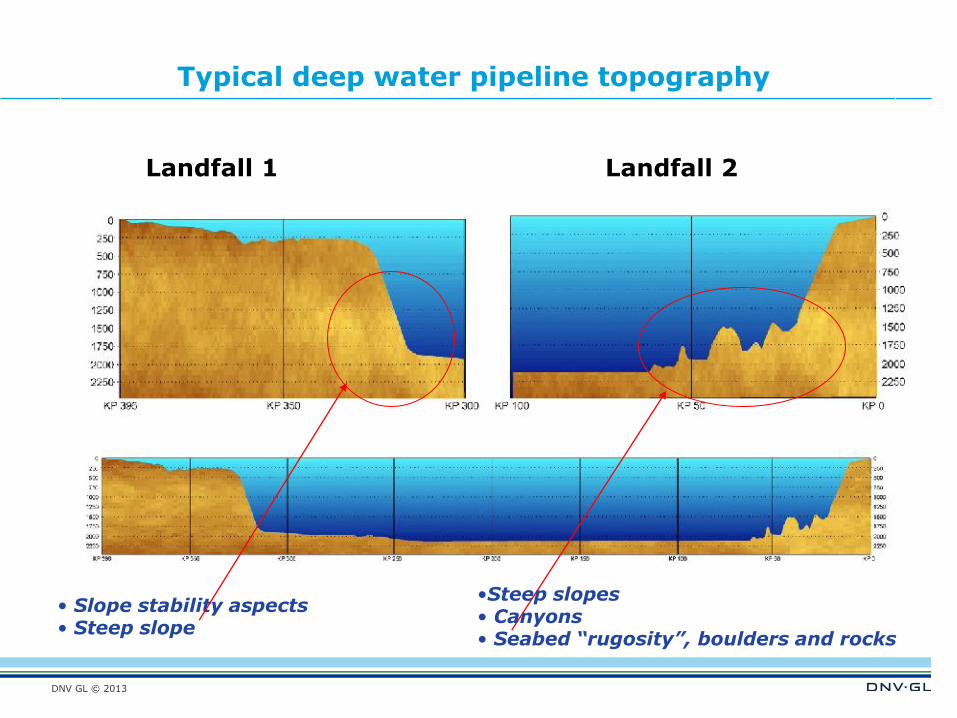
•Steep slopes • Canyons • Seabed “rugosity”, boulders and rocks
• Slope stability aspects • Steep slope
Typical deep water pipeline topography
Landfall 1 Landfall 2
DNV GL © 2013
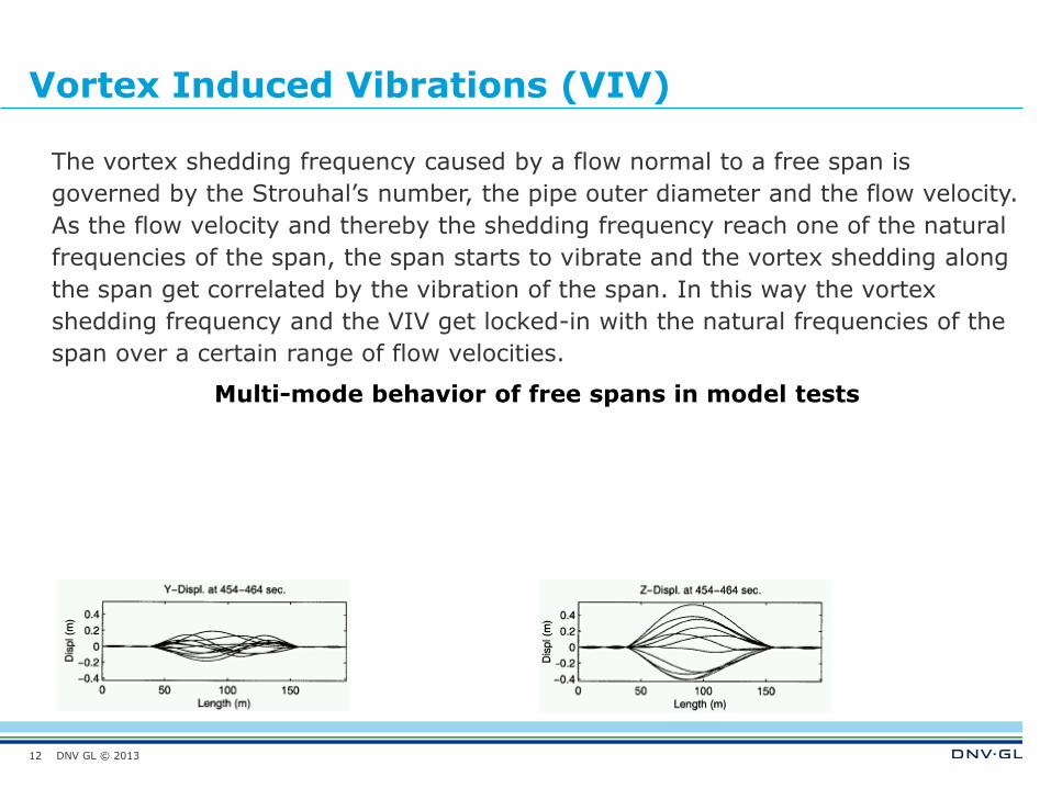
Vortex Induced Vibrations (VIV)
The vortex shedding frequency caused by a flow normal to a free span is
governed by the Strouhal’s number, the pipe outer diameter and the flow velocity.
As the flow velocity and thereby the shedding frequency reach one of the natural
frequencies of the span, the span starts to vibrate and the vortex shedding along
the span get correlated by the vibration of the span. In this way the vortex
shedding frequency and the VIV get locked-in with the natural frequencies of the
span over a certain range of flow velocities.
Multi-mode behavior of free spans in model tests
12
DNV GL © 2013
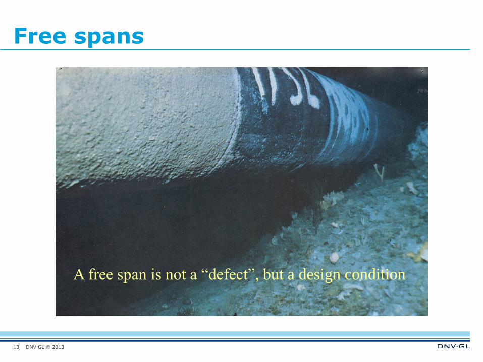
Free spans
13
A free span is not a “defect”, but a design condition
DNV GL © 2013
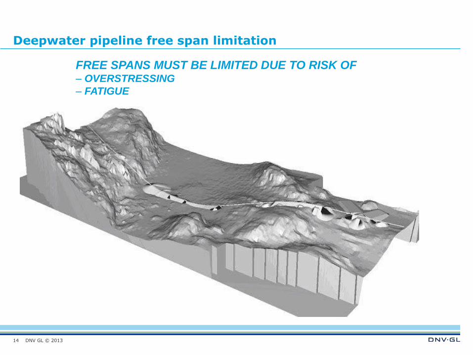
Deepwater pipeline free span limitation
14
FREE SPANS MUST BE LIMITED DUE TO RISK OF – OVERSTRESSING
– FATIGUE
DNV GL © 2013
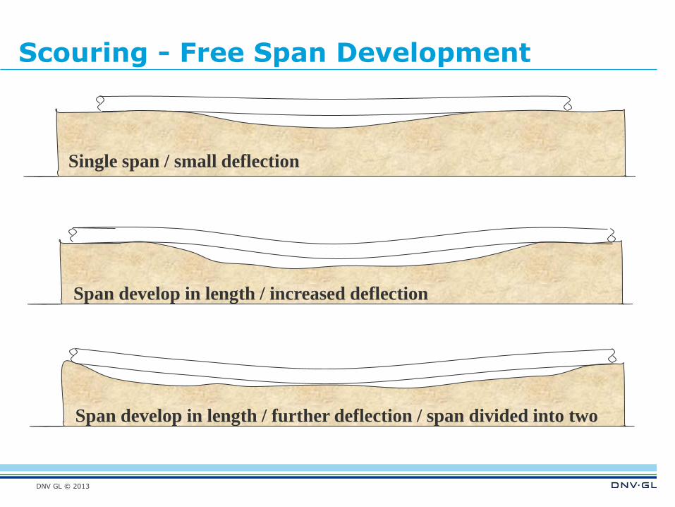
Scouring - Free Span Development
Span develop in length / increased deflection
Single span / small deflection
Span develop in length / further deflection / span divided into two
DNV GL © 2013
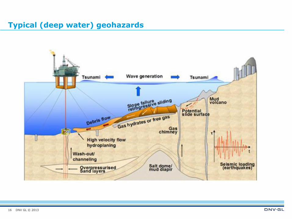
Typical (deep water) geohazards
16
DNV GL © 2013
Slide 17 02 May 2015
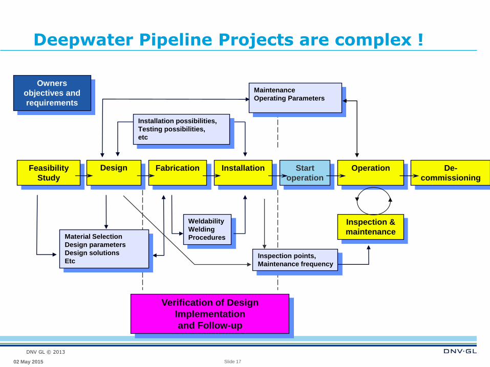
Deepwater Pipeline Projects are complex !
Verification of Design
Implementation
and Follow-up
Design
Fabrication
Installation
Installation possibilities,
Testing possibilities,
etc
Weldability
Welding
Procedures
Feasibility
Study
Maintenance
Operating Parameters
Operation
Start
operation
Inspection &
maintenance
De-
commissioning
Inspection points,
Maintenance frequency
Owners
objectives and
requirements
Material Selection
Design parameters
Design solutions
Etc
DNV GL © 2013
18
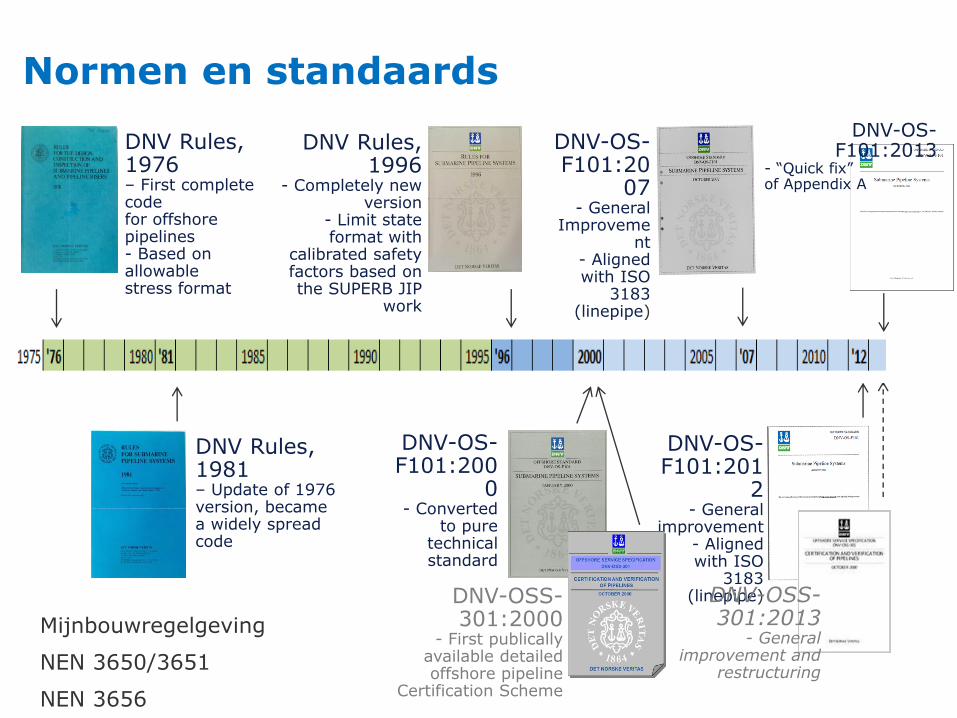
Normen en standaards
DNV-OS-F101:201
2 - General
improvement - Aligned with ISO
3183 (linepipe)
DNV-OS-F101:20
07 - General
Improvement
- Aligned with ISO
3183 (linepipe)
DNV-OS-F101:200
0 - Converted
to pure technical standard
DNV Rules, 1996
- Completely new version
- Limit state format with
calibrated safety factors based on the SUPERB JIP
work
DNV Rules, 1981 – Update of 1976 version, became a widely spread code
DNV Rules, 1976 – First complete code for offshore pipelines - Based on allowable stress format
DNV-OSS-301:2000
- First publically available detailed offshore pipeline
Certification Scheme
DNV-OSS-301:2013
- General improvement and
restructuring
DNV-OS-F101:2013
- “Quick fix” of Appendix A
5/2/2015
Mijnbouwregelgeving
NEN 3650/3651
NEN 3656
DNV GL © 2013
19
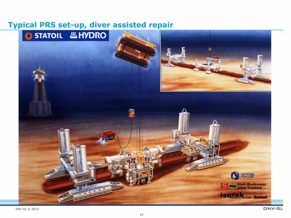
Typical PRS set-up, diver assisted repair
DNV GL © 2013
Materiaal aspecten
Rondheid
Wanddikte (tolerantie)
Chemische samenstelling (Ceq. etc.)
Re, Rm (Ramberg-Osgood parameters), breukrek
Charpy-V
DWTT
Coating
Field joint coating
Concrete
Etc.
20
DNV GL © 2013 21
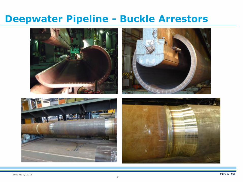
Deepwater Pipeline - Buckle Arrestors
DNV GL © 2013
SAFER, SMARTER, GREENER
www.dnvgl.com
CONTACTS
Private and confidential
22
Jan Spiekhout
+31-(0)507009865