InfraStruXure Manager - Installation and Configuration · InfraStruXure Manager 3 Safety...
26
InfraStruXure ™ Manager Installation and Configuration
Transcript of InfraStruXure Manager - Installation and Configuration · InfraStruXure Manager 3 Safety...
InfraStruXure™ Manager
Installation and Configuration

This manual is available in English on the enclosed CD.Dieses Handbuch ist in Deutsch auf der beiliegenden CD-ROM verfügbar.Deze handleiding staat in het Nederlands op de bijgevoegde cd.Este manual está disponible en español en el CD-ROM adjunto.Ce manuel est disponible en français sur le CD-ROM ci-inclus.Questo manuale è disponibile in italiano nel CD-ROM allegato.
Instrukcja Obslugi w jêzyku polskim jest dostêpna na CD.
您可以从包含的 CD 上获得本手册的中文版本。
Contents
Product Description..................................................1
Overview . . . . . . . . . . . . . . . . . . . . . . . . . . . . . . . . . . . . . . . . . 1Inventory . . . . . . . . . . . . . . . . . . . . . . . . . . . . . . . . . . . . . 1
Receiving inspection . . . . . . . . . . . . . . . . . . . . . . . . . . . . . 1
Please recycle . . . . . . . . . . . . . . . . . . . . . . . . . . . . . . . . . . 2
Disclaimer . . . . . . . . . . . . . . . . . . . . . . . . . . . . . . . . . . . . 2
Safety . . . . . . . . . . . . . . . . . . . . . . . . . . . . . . . . . . . . . . . . . . . . 3Rack-mounting safety . . . . . . . . . . . . . . . . . . . . . . . . . . . . . 3
Equipment containing a battery . . . . . . . . . . . . . . . . . . . . . . 3
Installation...............................................................4
Install the InfraStruXure Manager . . . . . . . . . . . . . . . . . . . . . . . 4Attach mounting brackets to the InfraStruXure Manager . . . . . 4
Mount the InfraStruXure Manager and switch (or hub) in an enclosure 5
Communication Connection . . . . . . . . . . . . . . . . . . . . . . . . . . . 7Network overview . . . . . . . . . . . . . . . . . . . . . . . . . . . . . . . 7
Connect network cables to InfraStruXure devices . . . . . . . . . . 7
Route network cables to the InfraStruXure Manager switch (or hub) 8
Install and route data cables (alternative routing) . . . . . . . . . . 8
Connect the InfraStruXure Manager and switch (or hub) . . . . . 9
Connect the InfraStruXure Manager to your LAN . . . . . . . . . . 9
Apply power to the InfraStruXure Manager and switch (or hub) 10
Remove power from the InfraStruXure Manager and switch (or hub) 10
Initial Configuration ...............................................11
Configure the InfraStruXure Manager . . . . . . . . . . . . . . . . . . . 11Configure the InfraStruXure Manager from the Private Network (APC LAN) 11
Configure the InfraStruXure Manager from the Public Network (User LAN) 12
How to Restore Access to the InfraStruXure Manager Server . . 13
Enable Remote Monitoring . . . . . . . . . . . . . . . . . . . . . . . . . . . 14
InfraStruXure Manager i
Product Information .............................................. 16APC InfraStruXure Manager front panel . . . . . . . . . . . . . . . 16
Specifications. . . . . . . . . . . . . . . . . . . . . . . . . . . . . . . . . . . . . . 17APC InfraStruXure Manager . . . . . . . . . . . . . . . . . . . . . . . 17
RS-485 Pin-out (COM 2) . . . . . . . . . . . . . . . . . . . . . . . . . . 18
Configure a building management system . . . . . . . . . . . . . 18
Life-Support Policy . . . . . . . . . . . . . . . . . . . . . . . . . . . . . . . . . . 19General policy . . . . . . . . . . . . . . . . . . . . . . . . . . . . . . . . 19
Examples of life-support devices . . . . . . . . . . . . . . . . . . . . 19
Warranty and Service . . . . . . . . . . . . . . . . . . . . . . . . . . . . . . . 20Limited warranty . . . . . . . . . . . . . . . . . . . . . . . . . . . . . . 20
Warranty limitations . . . . . . . . . . . . . . . . . . . . . . . . . . . . 20
Obtaining service . . . . . . . . . . . . . . . . . . . . . . . . . . . . . . 20
USA—FCC . . . . . . . . . . . . . . . . . . . . . . . . . . . . . . . . . . . 23
Canada—ICES . . . . . . . . . . . . . . . . . . . . . . . . . . . . . . . . 23
Japan—VCCI . . . . . . . . . . . . . . . . . . . . . . . . . . . . . . . . . 23
ii InfraStruXure Manager
Product Description
Overview
Inventory
Receiving inspection
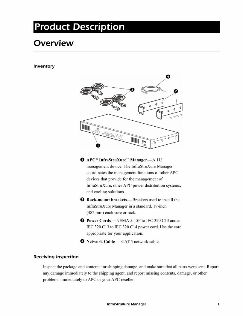
Inspect the package and contents for shipping damage, and make sure that all parts were sent. Report any damage immediately to the shipping agent, and report missing contents, damage, or other problems immediately to APC or your APC reseller.
APC® InfraStruXure� Manager�A 1U management device. The InfraStruXure Manager coordinates the management functions of other APC devices that provide for the management of InfraStruXure, other APC power distribution systems, and cooling solutions.
Rack-mount brackets� Brackets used to install the InfraStruXure Manager in a standard, 19-inch (482 mm) enclosure or rack.
Power Cords �NEMA 5-15P to IEC 320 C13 and an IEC 320 C13 to IEC 320 C14 power cord. Use the cord appropriate for your application.
Network Cable � CAT-5 network cable.
InfraStruXure Manager 1

Product Description: Overview
Please recycle
Disclaimer
American Power Conversion is not responsible for damage sustained during reshipment of this product.
The shipping materials are recyclable. Please save them for later use, or dispose of them appropriately.
2 InfraStruXure Manager
Safety
Rack-mounting safety
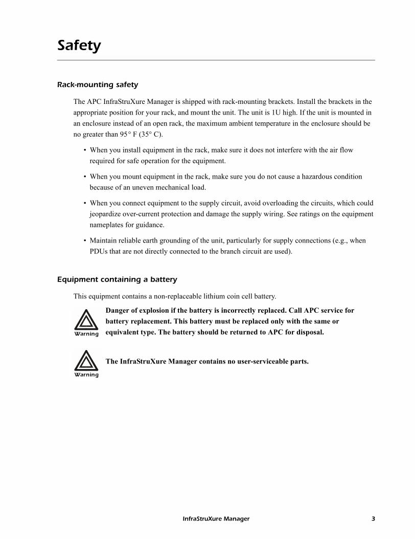
The APC InfraStruXure Manager is shipped with rack-mounting brackets. Install the brackets in the appropriate position for your rack, and mount the unit. The unit is 1U high. If the unit is mounted in an enclosure instead of an open rack, the maximum ambient temperature in the enclosure should be no greater than 95° F (35° C).
� When you install equipment in the rack, make sure it does not interfere with the air flow required for safe operation for the equipment.
� When you mount equipment in the rack, make sure you do not cause a hazardous condition because of an uneven mechanical load.
� When you connect equipment to the supply circuit, avoid overloading the circuits, which could jeopardize over-current protection and damage the supply wiring. See ratings on the equipment nameplates for guidance.
� Maintain reliable earth grounding of the unit, particularly for supply connections (e.g., when PDUs that are not directly connected to the branch circuit are used).
Equipment containing a battery
This equipment contains a non-replaceable lithium coin cell battery.
Warning
Danger of explosion if the battery is incorrectly replaced. Call APC service for battery replacement. This battery must be replaced only with the same or equivalent type. The battery should be returned to APC for disposal.
Warning
The InfraStruXure Manager contains no user-serviceable parts.
InfraStruXure Manager 3
Installation
Install the InfraStruXure Manager
Attach mounting brackets to the InfraStruXure Manager
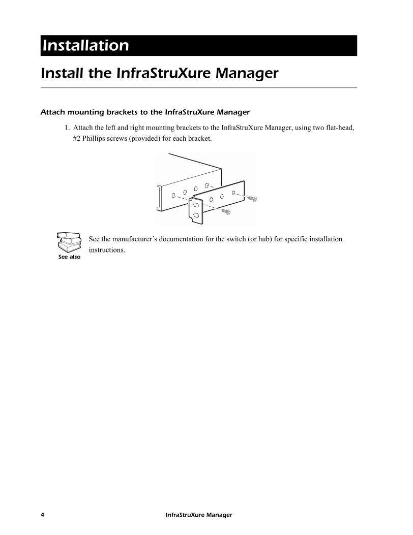
1. Attach the left and right mounting brackets to the InfraStruXure Manager, using two flat-head, #2 Phillips screws (provided) for each bracket.
See also
See the manufacturer�s documentation for the switch (or hub) for specific installation instructions.
4 InfraStruXure Manager
Installation: Install the InfraStruXure Manager
Mount the InfraStruXure Manager and switch (or hub) in an enclosure
Leave room above the switch (or hub) to route data cables.
To install the InfraStruXure Manager in a NetShelter enclosure:
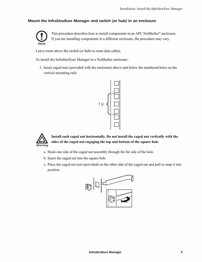
1. Insert caged nuts (provided with the enclosure) above and below the numbered holes on the vertical mounting rails
a. Hook one side of the caged nut assembly through the far side of the hole.
b. Insert the caged nut into the square hole
c. Place the caged nut tool (provided) on the other side of the caged nut and pull to snap it into position.
Note
This procedure describes how to install components in an APC NetShelter® enclosure. If you are installing components in a different enclosure, the procedure may vary.
Warning
Install each caged nut horizontally. Do not install the caged nut vertically with the sides of the caged nut engaging the top and bottom of the square hole.
1 U
InfraStruXure Manager 5
Installation: Install the InfraStruXure Manager
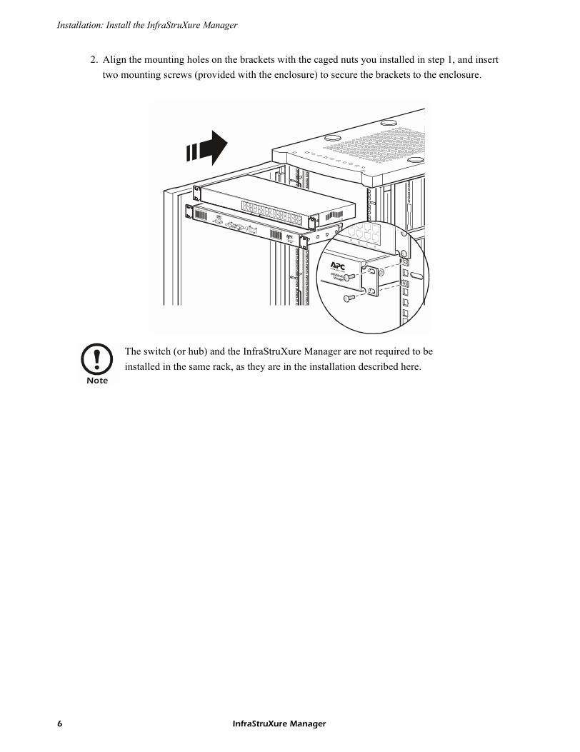
2. Align the mounting holes on the brackets with the caged nuts you installed in step 1, and insert two mounting screws (provided with the enclosure) to secure the brackets to the enclosure.
t
Note
The switch (or hub) and the InfraStruXure Manager are not required to be installed in the same rack, as they are in the installation described here.
6 InfraStruXure Manager
Communication Connection
Network overview
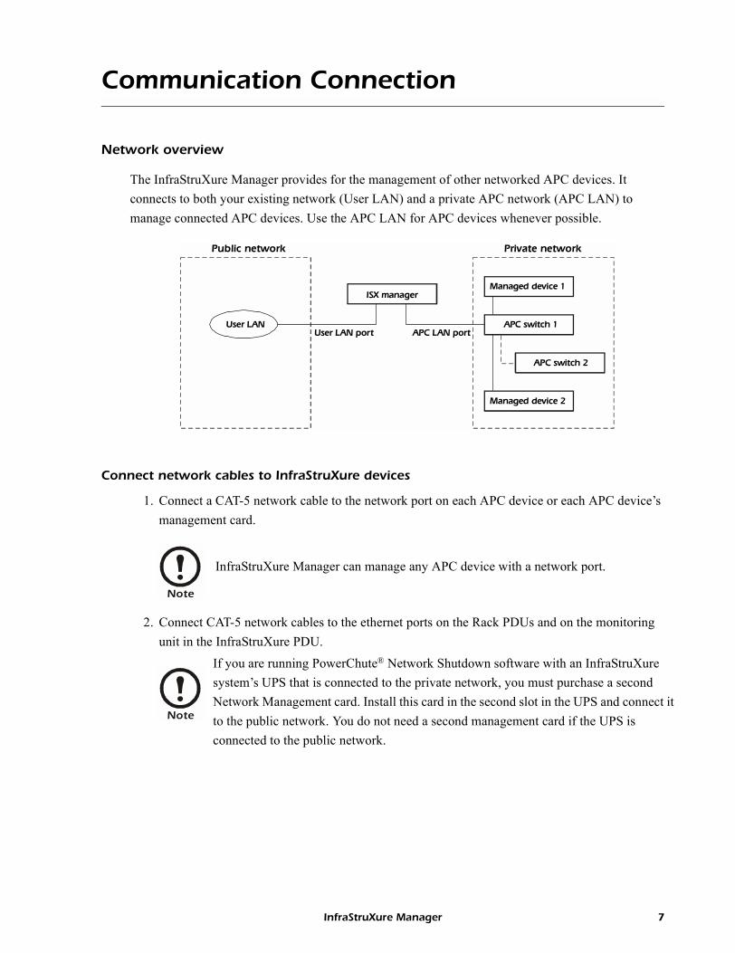
The InfraStruXure Manager provides for the management of other networked APC devices. It connects to both your existing network (User LAN) and a private APC network (APC LAN) to manage connected APC devices. Use the APC LAN for APC devices whenever possible.
Connect network cables to InfraStruXure devices
1. Connect a CAT-5 network cable to the network port on each APC device or each APC device�s management card.
2. Connect CAT-5 network cables to the ethernet ports on the Rack PDUs and on the monitoring unit in the InfraStruXure PDU.
APC LAN port
Managed device 2
User LANUser LAN port
APC switch 1
Private network
ISX manager
Public network
APC switch 2
Managed device 1
Note
InfraStruXure Manager can manage any APC device with a network port.
Note
If you are running PowerChute® Network Shutdown software with an InfraStruXure system�s UPS that is connected to the private network, you must purchase a second Network Management card. Install this card in the second slot in the UPS and connect it to the public network. You do not need a second management card if the UPS is connected to the public network.
InfraStruXure Manager 7
Installation: Communication Connection
Route network cables to the InfraStruXure Manager switch (or hub)
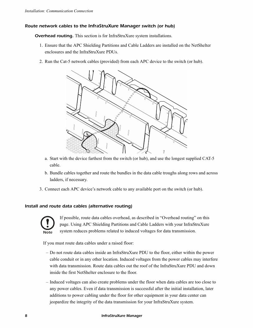
Overhead routing. This section is for InfraStruXure system installations.
1. Ensure that the APC Shielding Partitions and Cable Ladders are installed on the NetShelter enclosures and the InfraStruXure PDUs.
2. Run the Cat-5 network cables (provided) from each APC device to the switch (or hub).
a. Start with the device farthest from the switch (or hub), and use the longest supplied CAT-5 cable.
b. Bundle cables together and route the bundles in the data cable troughs along rows and across ladders, if necessary.
3. Connect each APC device�s network cable to any available port on the switch (or hub).
Install and route data cables (alternative routing)
If you must route data cables under a raised floor:
� Do not route data cables inside an InfraStruXure PDU to the floor, either within the power cable conduit or in any other location. Induced voltages from the power cables may interfere with data transmission. Route data cables out the roof of the InfraStruXure PDU and down inside the first NetShelter enclosure to the floor.
� Induced voltages can also create problems under the floor when data cables are too close to any power cables. Even if data transmission is successful after the initial installation, later additions to power cabling under the floor for other equipment in your data center can jeopardize the integrity of the data transmission for your InfraStruXure system.
Note
If possible, route data cables overhead, as described in �Overhead routing� on this page. Using APC Shielding Partitions and Cable Ladders with your InfraStruXure system reduces problems related to induced voltages for data transmission.
8 InfraStruXure Manager
Installation: Communication Connection
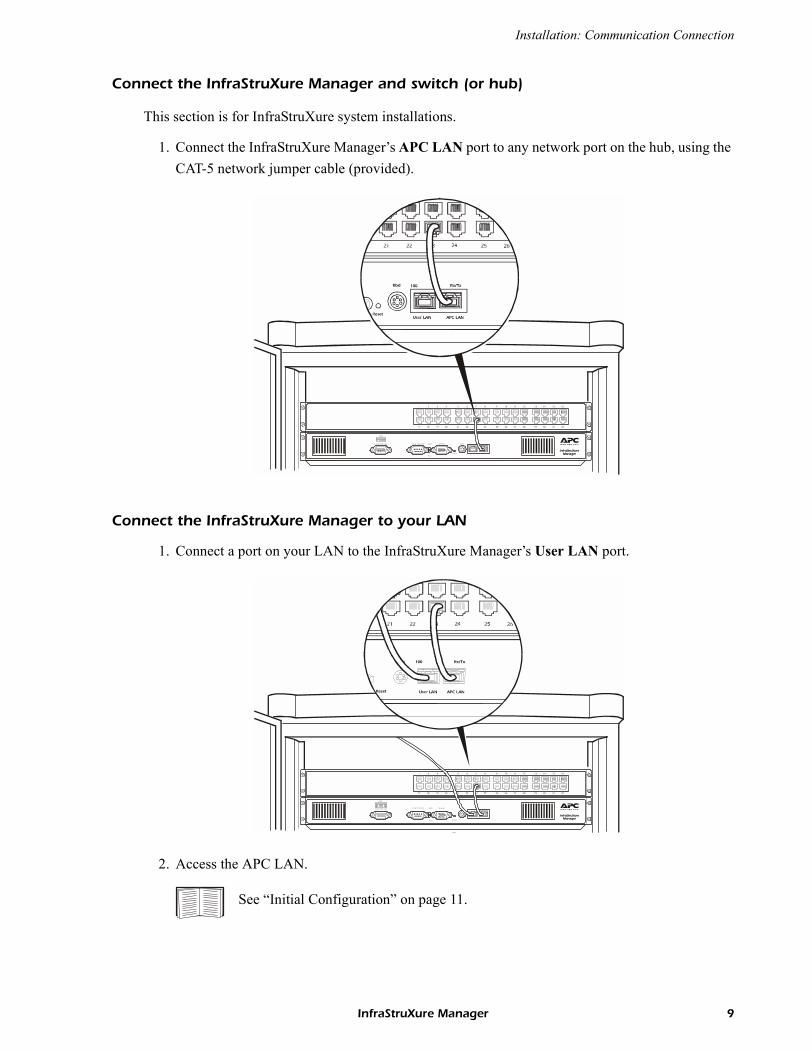
Connect the InfraStruXure Manager and switch (or hub)
This section is for InfraStruXure system installations.
1. Connect the InfraStruXure Manager�s APC LAN port to any network port on the hub, using the CAT-5 network jumper cable (provided).
.
Connect the InfraStruXure Manager to your LAN
1. Connect a port on your LAN to the InfraStruXure Manager�s User LAN port.
2. Access the APC LAN.
InfraStruXureManager
2 3 4 5 6 7 8 9 10 11 12 13 14 15 16
17 18 19 20 21 22 23 24 25 26 27 28 29 30 31 32
Link-Rx
ResetAPC LAN User LAN
100COM 2 RS-485 COM 1 RS-232
Pwr
HDD Monito r Kbd
USB1
See �Initial Configuration� on page 11.
InfraStruXureManager
2 3 4 5 6 7 8 9 10 11 12 13 14 15 16
17 18 19 20 21 22 23 24 25 26 27 28 29 30 31 32
Link-Rx
Reset APC LAN User LAN
100COM 2 RS-485 COM 1 RS-232
Pwr
HDD Monito r Kbd
ToUser LAN
USB1
InfraStruXure Manager 9
Installation: Communication Connection
Apply power to the InfraStruXure Manager and switch (or hub)
After you install the InfraStruXure Manager and switch (or hub) and make all of the communication connections, connect the power cords to a Rack PDU within the enclosure to apply power to the InfraStruXure Manager.
Remove power from the InfraStruXure Manager and switch (or hub)
If you need to remove power from the InfraStruXure Manager and switch (or hub), you must first shut down the manager from the client interface:
1. From the System Management menu, select Server and then Shutdown or Reboot Server....
2. In the Shutdown or Reboot Server window, select Shut Down Server, and click OK.
3. After the HDD LED has been inactive for 30 seconds, unplug the InfraStruXure Manager and switch (or hub) from the Rack PDU.
10 InfraStruXure Manager
Initial Configuration
Configure the InfraStruXure Manager
To configure the InfraStruXure Manager for the first time you must connect to the manager and run the APC InfraStruXure Manager Setup Wizard on the client interface. You have two options for connecting to the manager:
� Connect from the private network (APC LAN) with a computer connected to the APC switch (or hub). This method is recommended if you do not know the IP address assigned to the InfraStruXure Manager on the public network (User LAN), or your network does not use a DHCP server to assign IP addresses.
� Connect from the public network (User LAN). You can use this method if you know the IP address assigned to the InfraStruXure Manager on the public network (User LAN).
Configure the InfraStruXure Manager from the Private Network (APC LAN)
1. Connect a computer to a network port on the APC switch (or hub). The computer must meet the following requirements:
� It must be configured to automatically obtain an IP address (through DHCP).
� It must be running TCP/IP as a network protocol.
� The browser must be Microsoft® Internet Explorer, version 5.5 or higher.
2. Release and renew your computer�s IP address to assign it an address on the APC LAN.
3. Open Microsoft Internet Explorer browser, version 5.5 or higher, and enter the APC LAN IP address for the InfraStruXure Manager:
� Use 192.168.1.1 as the default IP address for the InfraStruXure Manager on the APC LAN.
� Use 10.0.1.1 if, for any reason, you cannot use the default IP address above.
4. If the Security Warning appears, click Yes to download the APC InfraStruXure Manager Client.
5. When the Server Log On display appears, use apc (lowercase) for both the username and password, and click Connect.
6. In the Confirm display, click Yes to run the APC InfraStruXure Manager Setup Wizard.
InfraStruXure Manager 11
Initial Configuration: Configure the InfraStruXure Manager
W
7. On the License Key page of the wizard, enter the license key to enable the InfraStruXure Manager to manage APC devices on the private network (APC LAN) or discover and manage APC devices on the public network (User LAN).
8. When you are done configuring your InfraStruXure Manager, click Finish to close the Wizard.
Configure the InfraStruXure Manager from the Public Network (User LAN)
1. Connect a computer to the public network (User LAN).
2. Open Microsoft Internet Explorer browser, version 5.5 or higher, and enter the IP address assigned to the APC InfraStruXure Manager. Ask your network administrator or check the DHCP server for this IP address.
3. If the Security Warning appears, click Yes to download the APC InfraStruXure Manager Client.
4. When the Server Log On display appears, use apc (lowercase) for both the username and password, and click Connect.
5. In the Confirm display, click Yes to run the APC InfraStruXure Manager Setup Wizard.W
6. On the License Key page of the wizard, enter the license key to enable the InfraStruXure Manager to manage APC devices on the private network (APC LAN) or discover and manage APC devices on the public network (User LAN).
7. When you are done configuring your InfraStruXure Manager, click Finish to close the Wizard.
Note
If you click No, you can run the wizard at any time. From the System Management menu, select the Server option and then select Setup Wizard.
Note
If you click No, you can run the wizard at any time. From the System Management menu, select the Server option and then select Setup Wizard.
12 InfraStruXure Manager
How to Restore Access to the InfraStruXure Manager Server
If the username or password used for local, Administrator access becomes unknown, or RADIUS only is selected in the �Authentication Settings� display and a RADIUS server is unavailable, you can use the following procedure to restore access to the InfraStruXure Manager server.
1. Connect a computer to the hub on the private network. That computer must have the InfraStruXure Manager client installed. If it does not, connect to the InfraStruXure Manager server and select to install the client, when prompted.
2. Reboot the InfraStruXure Manager server.
3. Use the InfraStruXure Manager client (step 1) to connect to the InfraStruXure Manager server.
4. When the �Server Log On� display appears, use admin (lowercase) as the Username, and apc (lowercase) as the Password, to log on to the server.
5. Select Authentication Settings in the System Management Menu to correct the problem that required using this procedure:
� Click Configure Local Users to use the �Configure local users� display to define a username and password for Administrator access.
� Change the Authentication Method setting to Local only.
Note
This may require physically disconnecting and reconnecting InfraStruXure Manager at its input power source.
Note
If a logon attempt fails, try again; the InfraStruXure Manager server may not have finished restarting. After the �Server Log On� display appears, you must log on within about eight minutes, or you must repeat step 1 through step 4.
InfraStruXure Manager 13
Enable Remote Monitoring
APC can monitor your InfraStruXure Manager and the devices it manages, and notify you of events via e-mail, pager, or phone. If you decide to use APC�s Remote Monitoring Service (RMS), follow these steps:
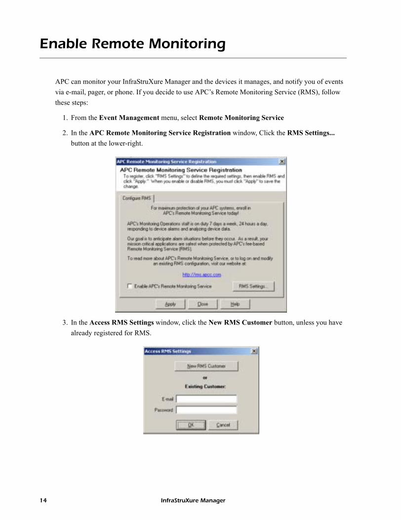
1. From the Event Management menu, select Remote Monitoring Service
2. In the APC Remote Monitoring Service Registration window, Click the RMS Settings... button at the lower-right.
3. In the Access RMS Settings window, click the New RMS Customer button, unless you have already registered for RMS.
14 InfraStruXure Manager
Initial Configuration: Enable Remote Monitoring
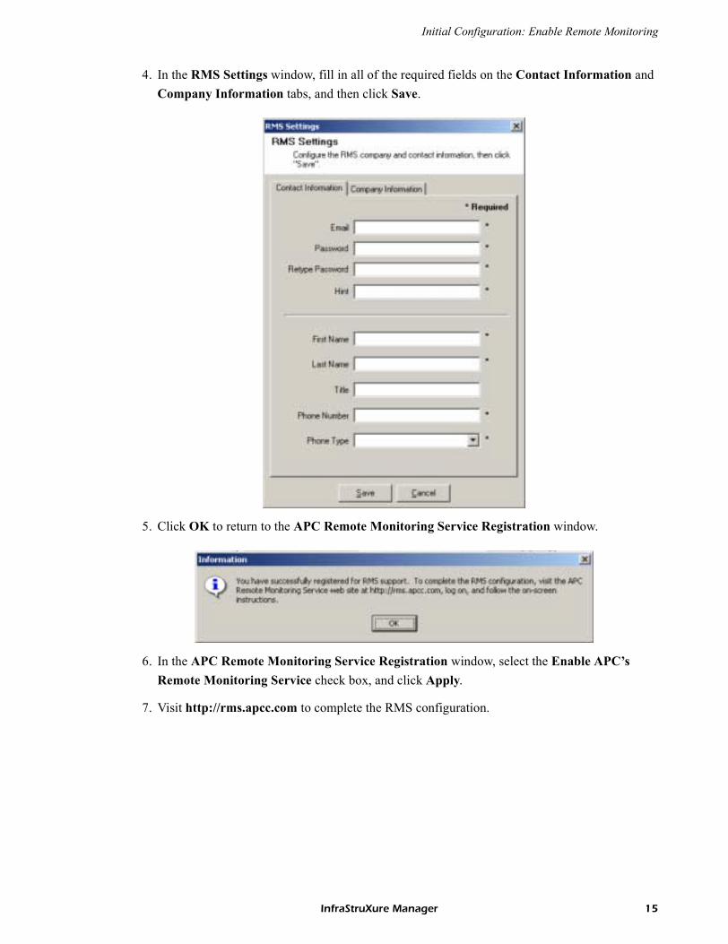
4. In the RMS Settings window, fill in all of the required fields on the Contact Information and Company Information tabs, and then click Save.
5. Click OK to return to the APC Remote Monitoring Service Registration window.
6. In the APC Remote Monitoring Service Registration window, select the Enable APC�s Remote Monitoring Service check box, and click Apply.
7. Visit http://rms.apcc.com to complete the RMS configuration.
InfraStruXure Manager 15
Product Information
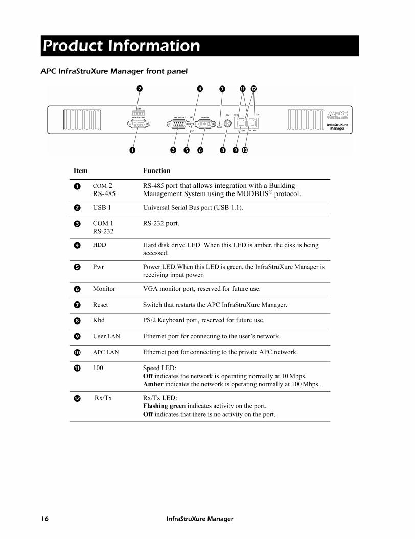
APC InfraStruXure Manager front panelItem Function
COM 2 RS-485
RS-485 port that allows integration with a Building Management System using the MODBUS® protocol.
USB 1 Universal Serial Bus port (USB 1.1).
COM 1 RS-232
RS-232 port.
HDD Hard disk drive LED. When this LED is amber, the disk is being accessed.
Pwr Power LED.When this LED is green, the InfraStruXure Manager is receiving input power.
Monitor VGA monitor port, reserved for future use.
Reset Switch that restarts the APC InfraStruXure Manager.
Kbd PS/2 Keyboard port, reserved for future use.
User LAN Ethernet port for connecting to the user�s network.
APC LAN Ethernet port for connecting to the private APC network.
100 Speed LED:Off indicates the network is operating normally at 10 Mbps.Amber indicates the network is operating normally at 100 Mbps.
Rx/Tx Rx/Tx LED:Flashing green indicates activity on the port.Off indicates that there is no activity on the port.
InfraStruXure ManagerReset
APC LANUser LAN
COM 2 RS-485 COM 1RS-232
Pwr
HDD MonitorKbd
USB1
Rx/Tx100
16 InfraStruXure Manager
Specifications
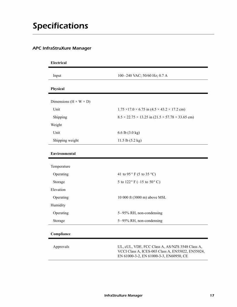
APC InfraStruXure Manager
Electrical
Input 100�240 VAC; 50/60 Hz; 0.7 A
Physical
Dimensions (H × W × D)
Unit 1.75 ×17.0 × 6.75 in (4.5 × 43.2 × 17.2 cm)
Shipping 8.5 × 22.75 × 13.25 in (21.5 × 57.78 × 33.65 cm)
Weight
Unit 6.6 lb (3.0 kg)
Shipping weight 11.5 lb (5.2 kg)
Environmental
Temperature
Operating 41 to 95 ° F (5 to 35 °C)
Storage 5 to 122° F (�15 to 50° C)
Elevation
Operating 10 000 ft (3000 m) above MSL
Humidity
Operating 5�95% RH, non-condensing
Storage 5�95% RH, non-condensing
Compliance
Approvals UL, cUL, VDE, FCC Class A, AS/NZS 3548 Class A, VCCI Class A, ICES-003 Class A, EN55022, EN55024, EN 61000-3-2, EN 61000-3-3, EN60950, CE
InfraStruXure Manager 17
Product Information: Specifications
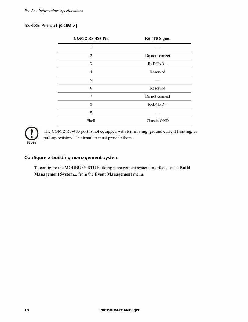
RS-485 Pin-out (COM 2)
Configure a building management system
To configure the MODBUS®-RTU building management system interface, select Build Management System... from the Event Management menu.
COM 2 RS-485 Pin RS-485 Signal
1 �
2 Do not connect
3 RxD/TxD +
4 Reserved
5 �
6 Reserved
7 Do not connect
8 RxD/TxD �
9 �
Shell Chassis GND
Note
The COM 2 RS-485 port is not equipped with terminating, ground current limiting, or pull-up resistors. The installer must provide them.
18 InfraStruXure Manager
Life-Support Policy
General policy
American Power Conversion (APC) does not recommend the use of any of its products in the following situations:
� In life-support applications where failure or malfunction of the APC product can be reasonably expected to cause failure of the life-support device or to affect significantly its safety or effectiveness.
� In direct patient care.
APC will not knowingly sell its products for use in such applications unless it receives in writing assurances satisfactory to APC that (a) the risks of injury or damage have been minimized, (b) the customer assumes all such risks, and (c) the liability of American Power Conversion is adequately protected under the circumstances.
Examples of life-support devicesThe term life-support device includes but is not limited to neonatal oxygen analyzers, nerve stimulators (whether used for anesthesia, pain relief, or other purposes), autotransfusion devices, blood pumps, defibrillators, arrhythmia detectors and alarms, pacemakers, hemodialysis systems, peritoneal dialysis systems, neonatal ventilator incubators, ventilators (for adults and infants), anesthesia ventilators, infusion pumps, and any other devices designated as �critical� by the U.S. FDA.
Hospital-grade wiring devices and leakage current protection may be ordered as options on many APC UPS systems. APC does not claim that units with these modifications are certified or listed as hospital-grade by APC or any other organization. Therefore these units do not meet the requirements for use in direct patient care.
InfraStruXure Manager 19
Warranty and Service
Limited warranty
APC warrants the InfraStruXure Manager to be free from defects in materials and workmanship for a period of two years from the date of purchase. Its obligation under this warranty is limited to repairing or replacing, at its own sole option, any such defective products. This warranty does not apply to equipment that has been damaged by accident, negligence, or misapplication or has been altered or modified in any way. This warranty applies only to the original purchaser.
Warranty limitations
Except as provided herein, APC makes no warranties, expressed or implied, including warranties of merchantability and fitness for a particular purpose. Some jurisdictions do not permit limitation or exclusion of implied warranties; therefore, the aforesaid limitation(s) or exclusion(s) may not apply to the purchaser.
Except as provided above, in no event will APC be liable for direct, indirect, special, incidental, or consequential damages arising out of the use of this product, even if advised of the possibility of such damage.
Specifically, APC is not liable for any costs, such as lost profits or revenue, loss of equipment, loss of use of equipment, loss of software, loss of data, costs of substitutes, claims by third parties, or otherwise. This warranty gives you specific legal rights and you may also have other rights, which vary according to jurisdiction.
Obtaining service
To obtain support for problems with your InfraStruXure Manager:0
1. Note the serial number and date of purchase. Obtain the serial number from the rear of the box, or from the About option of the Help menu.
2. Contact Customer Support at a phone number on the back cover of this manual. A technician will try to help you solve the problem by phone.
3. If you must return the product, the technician will give you a return material authorization (RMA) number. If the warranty expired, you will be charged for repair or replacement.
4. Pack the unit carefully. The warranty does not cover damage sustained in transit. Enclose a letter with your name, address, RMA number and daytime phone number; a copy of the sales receipt; and a check as payment, if applicable.
5. Mark the RMA number clearly on the outside of the shipping carton.
6. Ship by insured, prepaid carrier to the address provided by the Customer Support technician.
20 InfraStruXure Manager
aRadio Frequency Interference
USA—FCC This equipment has been tested and found to comply with the limits for a Class A digital device, pursuant to part 15 of the FCC Rules. These limits are designed to provide reasonable protection against harmful interference when the equipment is operated in a commercial environment. This equipment generates, uses, and can radiate radio frequency energy and, if not installed and used in accordance with this user manual, may cause harmful interference to radio communications. Operation of this equipment in a residential area is likely to cause harmful interference. The user will bear sole responsibility for correcting such interference.
Canada—ICES This Class A digital apparatus complies with Canadian ICES-003.
Cet appareil numérique de la classe A est conforme à la norme NMB-003 du Canada.
Japan—VCCI This is a Class A product based on the standard of the Voluntary Control Council for Interference by Information Technology Equipment (VCCI). If this equipment is used in a domestic environment, radio disturbance may occur, in which case, the user may be required to take corrective actions.
この装置は、情報処理装置等電波障害自主規制協議会(VCCI)の基準に基づくクラス A 情報技術装置です。この装置を家庭環境で使用
すると、電波妨害を引き起こすことがあります。この場合には、使
用者が適切な対策を講ずるように要求されることがあります。
Warning
Changes or modifications to this unit not expressly approved by the party responsible for compliance could void the user�s authority to operate this equipment.

*990-1636C-001*
APC Worldwide Customer Support
Customer support for this or any other APC product is available at no charge in any of the following ways:� Visit the APC Web site to access documents in the APC Knowledge Base and to submit customer
support requests.� www.apc.com (Corporate Headquarters)
Connect to localized APC Web sites for specific countries, each of which provides customer support information.
� www.apc.com/support/Global support searching APC Knowledge Base and using e-support.
� Contact an APC Customer Support center by telephone or e-mail.� Regional centers:
� Local, country-specific centers: go to www.apc.com/support/contact for contact information.
Contact the APC representative or other distributor from whom you purchased your APC product for information on how to obtain local customer support.
Direct InfraStruXure Customer Support Line (1)(877)537-0607 (toll free)
APC headquarters U.S., Canada (1)(800)800-4272 (toll free)
Latin America (1)(401)789-5735 (USA)
Europe, Middle East, Africa (353)(91)702000 (Ireland)
Japan (0) 35434-2021
Australia, New Zealand, South Pacific area (61) (2) 9955 9366 (Australia)
Entire contents copyright © 2004 American Power Conversion. All rights reserved. Reproduction in whole or in part without permission is prohibited. APC, the APC logo,
NetShelter, PowerChute, and InfraStruXure are trademarks of American Power Conversion Corporation and may be registered in some jurisdictions. All other trademarks, product names, and corporate names are the property of their respective owners and are used for
informational purposes only.
990-1636C-001 10/2004