Home Automation FM DTMF
5
Jim's Weird Wired World Simple Remote Control Unit This is a simple wireless remote control unit, which was originally designed for a model hovercraft which I was developing with the help of my friend Uday Arya. The project has been discontinued for techni cal reasons, but this remote control unit surv ives. The method used seems to be quite popular among many remote control units. Overview Block Diagram The controller consists of a Dual-tone mul tif requency (DTMF) encoder based on the UM91214 Telephone dialler IC. This versatile chip contains a keyboard matrix scanning section and a dialler. The dialler can be used in both pulse dialling as well as tone dialling modes. We are interested only in tone dialling, since we need the DTMF signals for control. The DTMF signals produced consist of two distinct frequencies summed together. The pair of frequencies is unique for every key on the standard telephone keypad. The encoded signal is now within the audio band, and can hence be sent to the modula tor. The modulator is a commercial ly avail abl e FM mi cro phone kit . Since the mic rophone kit expects input volt age to be in millivolts, the output of the dialler IC is attenuated. The FM transmit ter is set to a fr equency of about 100MHz. Operation of this section can be checked by using any FM reci ever tuned to the same fr equency as the FM transmit ter. Pressing any of the buttons attached to the encoder should produce a clear tone in the reciever. If the tone sounds noisy, try tuning the reciever carefully. In case the tone sounds harsh, the reciever may be ov er mo dulati ng, in whic h case the at te nuat ion must be increased. If it is too faint, then the attenuation must be reduced. It
-
Upload
ravindra-babu-potineedi -
Category
Documents
-
view
224 -
download
0
Transcript of Home Automation FM DTMF
8/3/2019 Home Automation FM DTMF
http://slidepdf.com/reader/full/home-automation-fm-dtmf 1/5
Jim's Weird Wired World
Simple Remote Control Unit
This is a simple wireless remote control unit, which was originallydesigned for a model hovercraft which I was developing with thehelp of my friend Uday Arya. The project has been discontinued fortechnical reasons, but this remote control unit survives. Themethod used seems to be quite popular among many remotecontrol units.
Overview
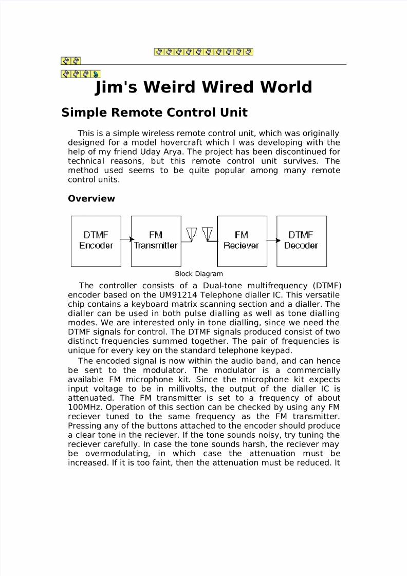
Block Diagram
The controller consists of a Dual-tone multifrequency (DTMF)encoder based on the UM91214 Telephone dialler IC. This versatile
chip contains a keyboard matrix scanning section and a dialler. Thedialler can be used in both pulse dialling as well as tone diallingmodes. We are interested only in tone dialling, since we need theDTMF signals for control. The DTMF signals produced consist of twodistinct frequencies summed together. The pair of frequencies isunique for every key on the standard telephone keypad.
The encoded signal is now within the audio band, and can hencebe sent to the modulator. The modulator is a commerciallyavailable FM microphone kit. Since the microphone kit expectsinput voltage to be in millivolts, the output of the dialler IC isattenuated. The FM transmitter is set to a frequency of about
100MHz. Operation of this section can be checked by using any FMreciever tuned to the same frequency as the FM transmitter.Pressing any of the buttons attached to the encoder should producea clear tone in the reciever. If the tone sounds noisy, try tuning thereciever carefully. In case the tone sounds harsh, the reciever maybe overmodulating, in which case the attenuation must beincreased. If it is too faint, then the attenuation must be reduced. It
8/3/2019 Home Automation FM DTMF
http://slidepdf.com/reader/full/home-automation-fm-dtmf 2/5
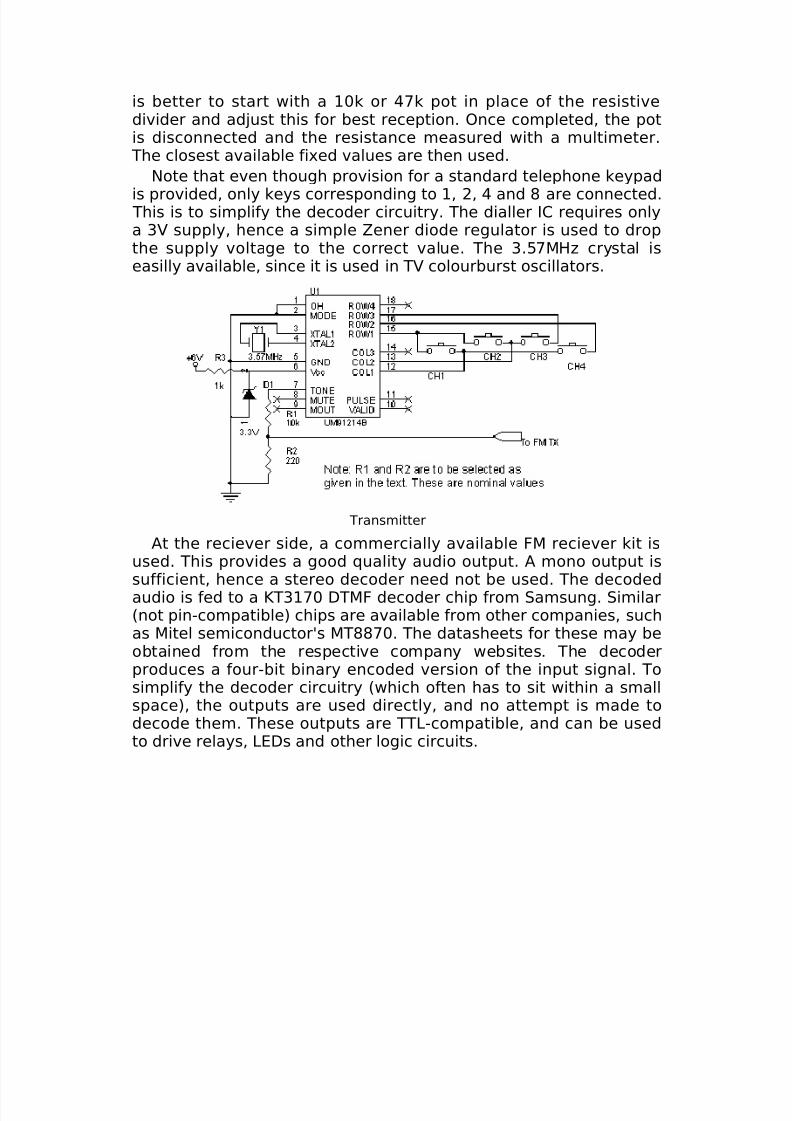
is better to start with a 10k or 47k pot in place of the resistivedivider and adjust this for best reception. Once completed, the potis disconnected and the resistance measured with a multimeter. The closest available fixed values are then used.
Note that even though provision for a standard telephone keypad
is provided, only keys corresponding to 1, 2, 4 and 8 are connected. This is to simplify the decoder circuitry. The dialler IC requires onlya 3V supply, hence a simple Zener diode regulator is used to dropthe supply voltage to the correct value. The 3.57MHz crystal iseasilly available, since it is used in TV colourburst oscillators.
Transmitter
At the reciever side, a commercially available FM reciever kit isused. This provides a good quality audio output. A mono output issufficient, hence a stereo decoder need not be used. The decodedaudio is fed to a KT3170 DTMF decoder chip from Samsung. Similar(not pin-compatible) chips are available from other companies, suchas Mitel semiconductor's MT8870. The datasheets for these may beobtained from the respective company websites. The decoderproduces a four-bit binary encoded version of the input signal. Tosimplify the decoder circuitry (which often has to sit within a smallspace), the outputs are used directly, and no attempt is made todecode them. These outputs are TTL-compatible, and can be usedto drive relays, LEDs and other logic circuits.

8/3/2019 Home Automation FM DTMF
http://slidepdf.com/reader/full/home-automation-fm-dtmf 3/5
Reciever
The CMOS CD4013 dual D-type latches are used in a togglefashion, such that their outputs change state whenever the inputstoggle. The latched outputs can then be used directly to drive alogic circuit, or through a transistor driver to switch on or off a smallload. A relay can be driven through a transistor driver to control anAC load, such as a lightbulb or a TV. Please take extreme care while
constructing circuits dealing with AC voltages. Make sure all high-voltage sections are well insulated. If you have no experience withAC circuits, please seek assistance during construction.
Output Drivers

8/3/2019 Home Automation FM DTMF
http://slidepdf.com/reader/full/home-automation-fm-dtmf 4/5
Construction
This project was constructed mostly on Veroboard, except for theFM transmitter and reciever kits, which had their own custom PCBs.Here is a picture of the transmitter.
Transmitter
From left to right, it's the battery case, parallel-port interface,main PCB (with the DTMF encoder) and FM Transmitter kit. Parallelport interface makes use of a CD4066 quad analog switch toreplace the four switches in the transmitter side. These are thencontrolled by D0-D3 on the parallel port. Hence, the remotelycontrolled device can now be under computer control. My testremote control device was this LEGO cart, which could moveforwards and backwards, as well as turn on and off it's headlights(Orange LEDs) and rooftop light (Red LED)
8/3/2019 Home Automation FM DTMF
http://slidepdf.com/reader/full/home-automation-fm-dtmf 5/5
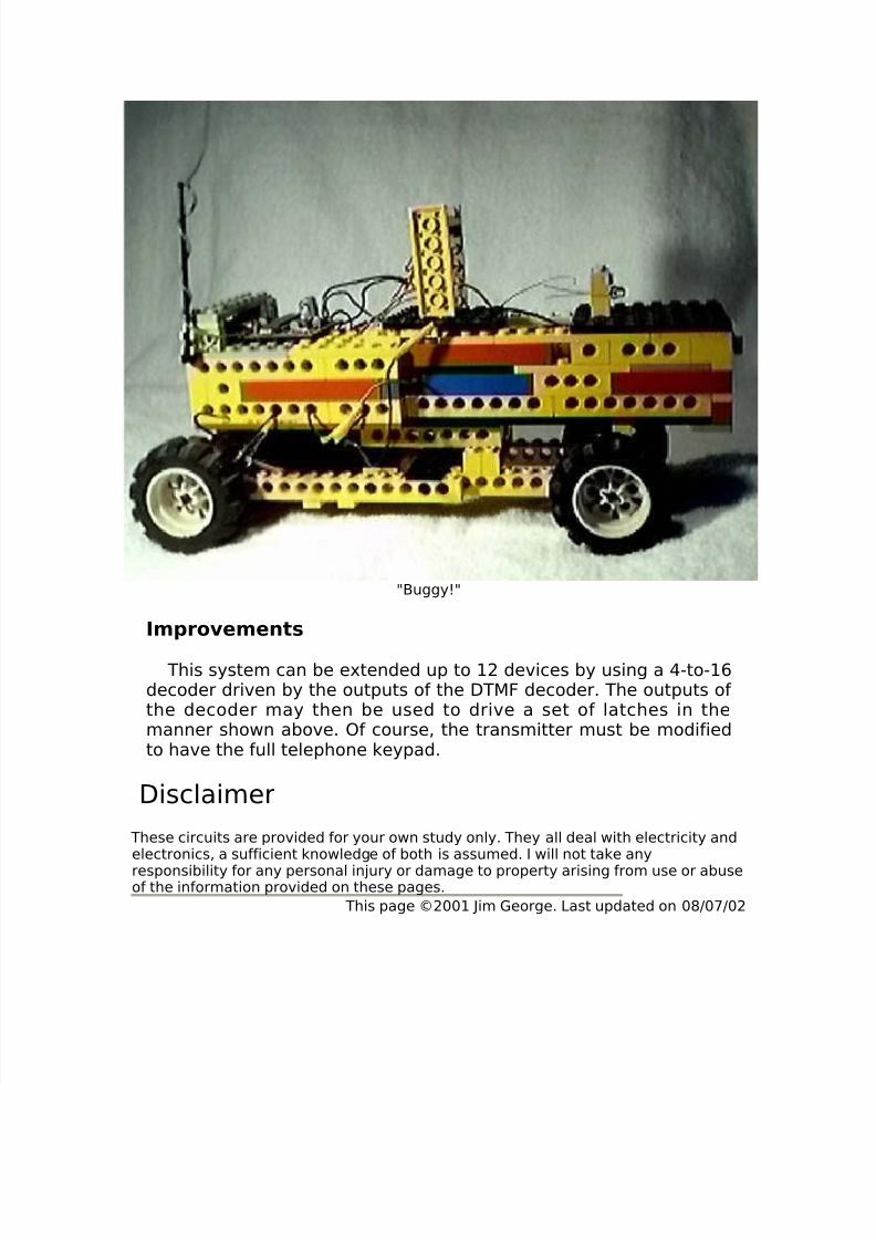
"Buggy!"
Improvements
This system can be extended up to 12 devices by using a 4-to-16decoder driven by the outputs of the DTMF decoder. The outputs of the decoder may then be used to drive a set of latches in themanner shown above. Of course, the transmitter must be modifiedto have the full telephone keypad.
Disclaimer
These circuits are provided for your own study only. They all deal with electricity andelectronics, a sufficient knowledge of both is assumed. I will not take any
responsibility for any personal injury or damage to property arising from use or abuseof the information provided on these pages.
This page ©2001 Jim George. Last updated on 08/07/02