Heating Cooling Fresh Air Clean Air
52
Heating Cooling Fresh Air Clean Air ComfoConnect LAN C Handleiding Manual Betriebsanleitung Manuel Manuale Instrukcja obsługi
Transcript of Heating Cooling Fresh Air Clean Air
Heating Cooling Fresh Air Clean Air
ComfoConnect LAN C HandleidingManualBetriebsanleitungManuelManualeInstrukcja obsługi
2 - NL
Voorwoord
Lees dit document vóór gebruik zorgvuldig door.
Dit document bevat alle aanvullende informatie die bijdraagt aan een veilige en optimale bediening, installatie en onderhoud van de ComfoConnect LAN C (vanaf hier “de unit” genoemd). De unit is onderworpen aan voortdurende ontwikkeling en verbetering. Hierdoor is het mogelijk dat de unit enigszins afwijkt van de omschrijvingen.
VragenNeem contact op met de leverancier als u vragen heeft. Op het achterblad van deze handleiding vindt u een lijst met contactgegevens van de belangrijkste leveranciers.
Elektrische gevarenTijdens de installatie of gedurende het onderhoud bestaat het gevaar van een elektrische schok. Neem steeds de veiligheidsvoorschriften in deze handleiding in acht. Het niet opvolgen van veiligheidsvoorschriften, waarschuwingen, opmerkingen en instructies kan leiden tot persoonlijk letsel of schade aan de unit. Haal de stroom van de ComfoAir Q, Comfort Vent Q of Aeris NEXT (vanaf hier “ventilatie-unit” genoemd) af voordat er iets op de unit wordt aangesloten of verwijderd.
Alle rechten voorbehouden.Dit document is met de grootste zorgvuldigheid samengesteld. De uitgever kan echter niet verantwoordelijk worden gehouden voor enige schade ontstaan door het ontbreken of onjuist vermelden van informatie in dit document. In geval van onenigheid is de Nederlandse tekst leidend.
3 - NL
Inhoudsopgave
Voorwoord .................................................................................................. 2
1 Inleiding ...................................................................................................... 4
2 Gebruik van de ComfoConnect LAN C ......................................................... 5
2.1 Status LED indicatie tijdens normaal gebruik ......................................... 6
2.2 Reset ................................................................................................... 6
2.3 Factory reset......................................................................................... 6
2.4 Storingen opheffen ............................................................................... 6
3 Technische specificaties .............................................................................. 7
4 Installatie ..................................................................................................... 8
5 In bedrijf nemen ........................................................................................... 9
6 Onderhoud .................................................................................................. 9
7 Garantie ...................................................................................................... 9
4 - NL
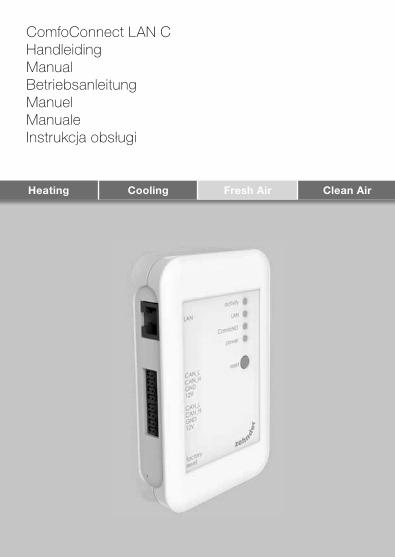
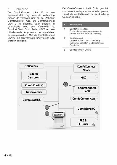
1 InleidingDe ComfoConnect LAN C is een apparaat dat zorgt voor de verbinding tussen de ventilatie-unit en de ‘Zehnder ComfoControl’ App. De ComfoConnect LAN C is geschikt voor gebruik in combinatie met een ComfoAir Q, Comfort Vent Q of Aeris NEXT en een bijbehorende App (voor de installateur en eindgebruiker). Met de ComfoConnect LAN C kan één ventilatie-unit via een App worden geregeld.
De ComfoConnect LAN C is geschikt voor wandmontage en zal worden gevoed vanuit de ventilatie-unit via de 4 aderige ComfoNet kabel.
# Beschrijving
1 ComfoNet interfaceProtocol over een gecombineerde seriële bus met +12V DC voeding.
2 Ventilatie-unitLevert o.a. de +12V DC voeding voor alle apparaten (onderdelen) op ComfoNet.
3 ComfoConnect LAN C
KNX
ComfoControl App
ComfoConnectLAN C
ComfoConnect KNX C
ComfoCool-L Q
Naverwarmer
Externe Sensoren
Option Box
RFZ & RFZ & RF-RF-Timer
ComfoSense CComfoSense C
ComfoSwitch C
Display
1
2
3
5 - NL
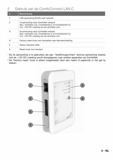
2 Gebruik van de ComfoConnect LAN C# Beschrijving
1 LAN aansluiting (RJ45) naar netwerk.
2 1e aansluiting naar ComfoNet netwerk (bijv. ventilatie-unit, ComfoSense C of ComfoSwitch C), incl. +12V DC voeding van de ventilatie-unit.
31 2e aansluiting naar ComfoNet netwerk (bijv. ventilatie-unit, ComfoSense C of ComfoSwitch C), incl. +12V DC voeding van de ventilatie-unit.
42 Factory reset knop voor herstellen naar fabrieksinstelling.
5 Status indicatie LEDs.
6 Reset knop voor herstart.
1 De 2e aansluiting is te gebruiken als zgn. ‘feedthrough/chain’ doorlus aansluiting waarbij ook de +12V DC voeding wordt doorgegeven naar andere apparaten op ComfoNet.
2 De ‘Factory reset’ knop is alleen toegankelijk door een naald of paperclip in het gat te steken.
1
2
5
6
3
4
6 - NL
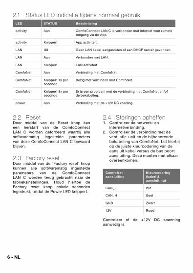
2.1 Status LED indicatie tijdens normaal gebruik LED STATUS Beschrijving
activity Aan ComfoConnect LAN C is verbonden met internet voor remote toegang via de App.
activity Knippert App activiteit.
LAN Uit Geen LAN kabel aangesloten of een DHCP server gevonden.
LAN Aan Verbonden met LAN.
LAN Knippert LAN activiteit.
ComfoNet Aan Verbinding met ComfoNet.
ComfoNet Knippert 1x per seconde
Bezig met verbinden met ComfoNet.
ComfoNet Knippert 8x per seconde
Er is een probleem met de verbinding met ComfoNet en/of de bekabeling.
power Aan Verbinding met de +12V DC voeding.
2.2 ResetDoor middel van de Reset knop kan een herstart van de ComfoConnect LAN C worden geforceerd waarbij alle softwarematig ingestelde parameters van deze ComfoConnect LAN C bewaard blijven.
2.3 Factory resetDoor middel van de ‘Factory reset’ knop kunnen alle softwarematig ingestelde parameters van de ComfoConnect LAN C worden terug gebracht naar de fabrieksinstellingen. Houd hiertoe de Factory reset knop enkele seconden ingedrukt, totdat de Power LED knippert.
2.4 Storingen opheffen1. Controleer de netwerk- en
internetverbinding.2. Controleer de verbinding met de
ventilatie-unit en de bijbehorende bekabeling van ComfoNet. Let hierbij op de juiste kleurcodering van de aansluit kabel versus de bus poort aansluiting. Deze moeten met elkaar overeenkomen.
ComfoNet aansluiting
Kleurcodering (kabel & aansluiting)
CAN_L Wit
CAN_H Geel
GND Zwart
12V Rood
Controleer of de +12V DC spanning aanwezig is.
7 - NL
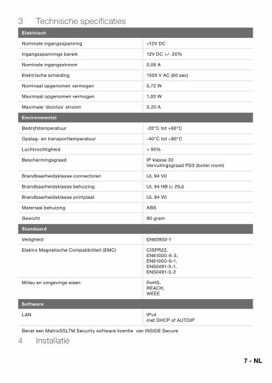
3 Technische specificatiesElektrisch
Nominale ingangsspanning +12V DC
Ingangsspannings bereik 12V DC +/- 20%
Nominale ingangsstroom 0,06 A
Elektrische scheiding 1500 V AC (60 sec)
Nominaal opgenomen vermogen 0,72 W
Maximaal opgenomen vermogen 1,00 W
Maximale ‘doorlus’ stroom 3,20 A
Environmental
Bedrijfstemperatuur -20°C tot +60°C
Opslag- en transporttemperatuur -40°C tot +80°C
Luchtvochtigheid < 95%
Beschermingsgraad IP klasse 30 Vervuilingsgraad PD3 (boiler room)
Brandbaarheidsklasse connectoren UL 94 V0
Brandbaarheidsklasse behuizing UL 94 HB (< 20J)
Brandbaarheidsklasse printplaat UL 94 V0
Materiaal behuizing ABS
Gewicht 90 gram
Standaard
Veiligheid EN60950-1
Elektro Magnetische Compatibiliteit (EMC) CISPR22, EN61000-6-3, EN61000-6-1, EN50491-5-1, EN50491-5-2
Milieu en omgevings eisen RoHS, REACH,WEEE
Software
LAN IPv4 met DHCP of AUTOIP
Bevat een MatrixSSLTM Security software licentie van INSIDE Secure
4 Installatie
8 - NL
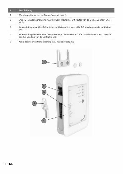
# Beschrijving
1 Wandbevestiging van de ComfoConnect LAN C.
2 LAN RJ45 kabel aansluiting naar netwerk (Router) of wifi router van de ComfoConnect LAN Kit C.
3 1e aansluiting naar ComfoNet (bijv. ventilatie-unit,), incl. +12V DC voeding van de ventilatie-unit.
4 2e aansluiting/doorlus naar ComfoNet (bijv. ComfoSense C of ComfoSwitch C), incl. +12V DC doorlus voeding van de ventilatie-unit.
5 Kabeldoorvoor en trekontlasting incl. wandbevestiging.
1
2
5
3
4
9 - NL
Haal de stroom van de ventilatie-unit af voordat u het apparaat installeert. Neem altijd de plaatselijke veiligheidsvoorschriften in acht.
De kabeleisen voor de ComfoNet interface kabel zijn:� Maximale lengte: 50m;� Aantal aders: 2x2 (twisted pair);� Afscherming: niet afgeschermd;� Kern: stijve (volle) draaden voor
insteekklemelementen;� Kleuren: compatibel met
connectoren;� Minimaal Ø: 0,2mm2;� Optimaal: DIN VDE 0281: J-Y(St)Y 2 x
2 x 0,6� Maximaal Ø: 1,5mm2.
De netwerkeisen zijn:� DHCP server actief;� Automatische IP adres afgifte actief.
1. Bevestig de ComfoConnect LAN C aan de wand. Bij voorkeur in de buurt van de ventilatie-unit.
2. Sluit de internet (LAN; RJ45, CAT 5 UTP) communicatiekabel aan op de ComfoConnect LAN C.
3. Sluit de gecombineerde bus-power kabel van de ComfoNet interface aan op een van de twee bus poorten op de ComfoConnect LAN C.
4. Sluit een tweede gecombineerde bus-power kabel van de ComfoNet interface aan op de andere beschikbare bus poort op de ComfoConnect LAN C, voor het doorlussen naar de eventueel andere apparaten in het netwerk, zoals een ComfoSense C, ComfoSwitch C.
5. Bevestig de trekontlasting aan de wand en gebruik deze als kabeldoorvoer voor alle kabels van en naar de ComfoConnect LAN C. Deze voorkomt dat de kabels uit het apparaat getrokken kunnen worden.
6. Sluit de gecombineerde bus-power kabel van de ComfoNet interface aan op een van de twee bus poorten op de ventilatie-unit.
7. Schakel de stroom in.
5 In bedrijf nemenDownload de ‘Zehnder ComfoControl’ App van de Apple App Store or Google Play Store.
Volg de instructie in de App om verbinding met het de ComfoConnect LAN C te maken. Hiervoor moet het apparaat waarop de app draait met hetzelfde netwerk verbonden zijn als de ComfoConnect LAN C.
Verder instellingen van de ComfoConnect LAN C zoals beveiligde remote toegang vrijgeven of blokkeren kunnen in de app worden gevonden.
6 OnderhoudVerwijder regelmatig het stof van de unit met een droge stofdoek.
7 GarantieDe fabrikant levert garantie op de unit voor een periode van 24 maanden na de installatie tot een maximum van 30 maanden na de productiedatum.
De garantie vervalt indien:� de installatie niet volgens de
geldende voorschriften is uitgevoerd;� de gebreken het gevolg zijn van
verkeerde aansluiting, ondeskundig gebruik of vervuiling van het systeem;
� onderdelen zijn gebruikt die niet door de fabrikant zijn geleverd of reparaties zijn uitgevoerd door onbevoegden.
De kosten van demontage en montage ter plaatse vallen buiten de garantiebepalingen. Dit geldt ook voor normale slijtage. De fabrikant behoudt zich het recht voor de constructie en/of configuratie van zijn producten op elk moment te wijzigen zonder de verplichting eerder geleverde producten aan te passen.
10 - EN
Foreword Please read this document carefully before use.
This document contains additional information for safe and optimal installation, operation and maintenance of the ComfoConnect LAN C (hereinafter referred to as “the unit’). The unit is subject to continuous development and improvement. It is therefore possible that the unit may differ slightly from the descriptions given in this document.
QueriesPlease contact the supplier if you have any queries. The rear page of this manual contains a list of contact details for the main suppliers.
Electrical dangersThere is a risk of electric shock during installation or maintenance. Always comply with the safety regulations in this manual. Personal injury or damage to the unit can arise from non-compliance with the safety regulations, warnings, comments and instructions in this manual. Disconnect the power supply to the ComfoAir Q, Comfort Vent Q or Aeris NEXT (hereinafter referred to as the “ventilation unit”) before connecting up or removing something from the unit.
All rights reserved.This manual has been drawn up with the utmost care. However the publisher cannot be held liable for any damage caused as a result of missing or incorrect information in this document. In case of disparity, the Dutch text takes precedent.
EN - 11
Table of contents Foreword ................................................................................................... 10
1 Introduction ............................................................................................... 12
2 Using the ComfoConnect LAN C ................................................................ 13
2.1 LED Status indicator during normal use ............................................... 14
2.2 Resetting ............................................................................................ 14
2.3 Factory reset....................................................................................... 14
2.4 Malfunction checks ............................................................................. 14
3 Technical specifications ............................................................................. 15
4 Installation ................................................................................................. 16
5 Commissioning .......................................................................................... 17
6 Maintenance ............................................................................................. 17
7 Guarantee ................................................................................................. 17
12 - EN
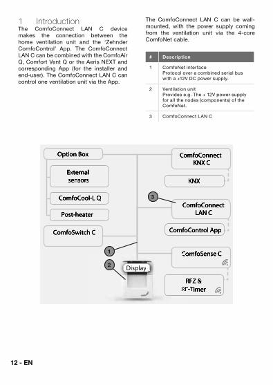
1 IntroductionThe ComfoConnect LAN C device makes the connection between the home ventilation unit and the ‘Zehnder ComfoControl’ App. The ComfoConnect LAN C can be combined with the ComfoAir Q, Comfort Vent Q or the Aeris NEXT and corresponding App (for the installer and end-user). The ComfoConnect LAN C can control one ventilation unit via the App.
The ComfoConnect LAN C can be wall-mounted, with the power supply coming from the ventilation unit via the 4-core ComfoNet cable.
# Description
1 ComfoNet interfaceProtocol over a combined serial bus with a +12V DC power supply.
2 Ventilation unitProvides e.g. The + 12V power supply for all the nodes (components) of the ComfoNet.
3 ComfoConnect LAN C
KNX
ComfoControl App
ComfoConnectLAN C
ComfoConnect KNX C
ComfoCool-L Q
Post-heater
External sensors
Option Box
RFZ & RFZ & RF-RF-Timer
ComfoSense CComfoSense C
ComfoSwitch C
Display
1
2
3
EN - 13
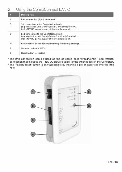
2 Using the ComfoConnect LAN C# Description
1 LAN connection (RJ45) to network.
2 1st connection to the ComfoNet network (e.g. ventilation unit, ComfoSense C or ComfoSwitch C), incl. +12V DC power supply of the ventilation unit.
31 2nd connection to the ComfoNet network (e.g. ventilation unit, ComfoSense C or ComfoSwitch C), incl. +12V DC power supply of the ventilation unit.
42 Factory reset button for implementing the factory settings.
5 Status of indicator LEDs.
6 Reset button for restart.
1 The 2nd connection can be used as the so-called ‘feed-through/chain’ loop-through connection that includes the +12V DC power supply for the other nodes on the ComfoNet.
2 The ‘Factory reset’ button is only accessible by inserting a pin or paper clip into the little hole.
1
2
5
6
3
4
14 - EN
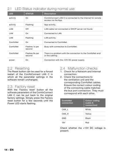
2.1 LED Status indicator during normal use LED STATUS Description
activity On ComfoConnect LAN C is connected to the Internet for remote access via the App.
activity Flashing App activity.
LAN Off LAN cable not connected or DHCP server not found.
LAN On Connected to LAN.
LAN Flashing LAN activity.
ComfoNet On Connected to ComfoNet.
ComfoNet Flashes 1x per second
Busy with connection to ComfoNet.
ComfoNet Flashes 8x per second
There is a problem with the connection to the ComfoNet and/or the cabling.
power On Connection with the +12V DC power supply.
2.2 ResettingThe Reset button can be used for a forced restart of the ComfoConnect LAN C in which all the parameter settings in the software remain unchanged.
2.3 Factory resetWith the ‘Factory reset’ button all the software parameters of the ComfoConnect LAN C can be put back to the original factory settings. Simply press the Factory reset button for a few seconds until the Power LED starts flashing.
2.4 Malfunction checks1. Check for a Network and Internet
connection.2. Check the connections to
the ventilation unit and the corresponding ComfoNet cables. Ensure the correct colour coding of the connecting cable matches the bus port connection. They must correspond with each other.
ComfoNet connection
Colour coding (cable & connection)
CAN_L White
CAN_H Yellow
GND Black
12V Red
Check whether the +12V DC voltage is present.
EN - 15
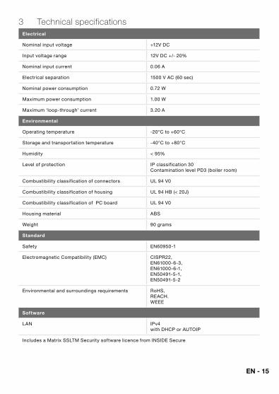
3 Technical specificationsElectrical
Nominal input voltage +12V DC
Input voltage range 12V DC +/- 20%
Nominal input current 0.06 A
Electrical separation 1500 V AC (60 sec)
Nominal power consumption 0.72 W
Maximum power consumption 1.00 W
Maximum ‘loop-through’ current 3.20 A
Environmental
Operating temperature -20°C to +60°C
Storage and transportation temperature -40°C to +80°C
Humidity < 95%
Level of protection IP classification 30 Contamination level PD3 (boiler room)
Combustibility classification of connectors UL 94 V0
Combustibility classification of housing UL 94 HB (< 20J)
Combustibility classification of PC board UL 94 V0
Housing material ABS
Weight 90 grams
Standard
Safety EN60950-1
Electromagnetic Compatibility (EMC) CISPR22, EN61000-6-3, EN61000-6-1, EN50491-5-1, EN50491-5-2
Environmental and surroundings requirements RoHS, REACH.WEEE
Software
LAN IPv4 with DHCP or AUTOIP
Includes a Matrix SSLTM Security software licence from INSIDE Secure
16 - EN
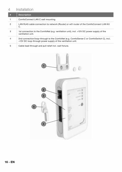
4 Installation# Description
1 ComfoConnect LAN C wall mounting.
2 LAN RJ45 cable connection to network (Router) or wifi router of the ComfoConnect LAN Kit C.
3 1st connection to the ComfoNet (e.g. ventilation unit), incl. +12V DC power supply of the ventilation unit.
4 2nd connection/loop-through to the ComfoNet (e.g. ComfoSense C or ComfoSwitch C), incl, +12V DC loop-through power supply of the ventilation unit.
5 Cable lead-through and pull relief incl. wall fixture.
1
2
5
3
4
EN - 17
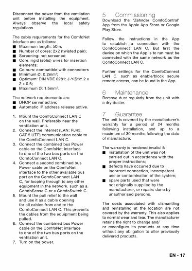
Disconnect the power from the ventilation unit before installing the equipment. Always observe the local safety regulations.
The cable requirements for the ComfoNet interface are as follows:� Maximum length: 50m;� Number of cores: 2x2 (twisted pair);� Screening: not screened;� Core: rigid (solid) wires for insertion
elements;� Colours: compatible with connectors� Minimum Ø: 0.2mm2;� Optimum: DIN VDE 0281: J-Y(St)Y 2 x
2 x 0.6;� Maximum Ø: 1.5mm2.
The network requirements are:� DHCP server active;� Automatic IP address release active.
1. Mount the ComfoConnect LAN C on the wall. Preferably near the ventilation unit.
2. Connect the Internet (LAN; RJ45, CAT 5 UTP) communication cable to the ComfoConnect LAN C.
3. Connect the combined bus Power cable on the ComfoNet interface to one of the two bus ports on the ComfoConnect LAN C.
4. Connect a second combined bus Power cable on the ComfoNet interface to the other available bus port on the ComfoConnect LAN C, for looping through to any other equipment in the network, such as a ComfoSense C or a ComfoSwitch C.
5. Mount the pull relief to the wall and use it as a cable opening for all cables from and to the ComfoConnect LAN C. This prevents the cables from the equipment being pulled.
6. Connect the combined bus Power cable on the ComfoNet interface to one of the two bus ports on the ventilation unit.
7. Turn on the power.
5 CommissioningDownload the ‘Zehnder ComfoControl’ App from the Apple App Store or Google Play Store.
Follow the instructions in the App to establish a connection with the ComfoConnect LAN C. But first the device on which the App is to run must be connected with the same network as the ComfoConnect LAN C.
Further settings for the ComfoConnect LAN C, such as enable/block secure remote access, can be found in the App.
6 MaintenanceRemove dust regularly from the unit with a dry duster.
7 GuaranteeThe unit is covered by the manufacturer’s warranty for a period of 24 months following installation, and up to a maximum of 30 months following the date of manufacture.
The warranty is rendered invalid if:� installation of the unit was not
carried out in accordance with the proper instructions;
� defects have occurred due to incorrect connection, incompetent use or contamination of the system;
� spare parts used that were not originally supplied by the manufacturer, or repairs done by unauthorised persons.
The costs associated with dismantling and reinstalling at the location are not covered by the warranty. This also applies to normal wear and tear. The manufacturer retains the right to change and/or reconfigure its products at any time without any obligation to alter previously delivered products.
18 - DE
Vorwort Bitte lesen Sie dieses Dokument vor dem Gebrauch sorgfältig durch.
Dieses Dokument enthält alle ergänzenden Informationen, die zu einer sicheren und optimalen Bedienung, Installation und Wartung von ComfoConnect LAN C (im Folgenden als „Gerät“ bezeichnet) beitragen. Das Gerät wird permanent weiterentwickelt und verbessert. Dadurch weicht das Gerät möglicherweise ein wenig von den Beschreibungen ab.
FragenBei Fragen wenden Sie sich bitte an Ihren Lieferanten. Auf der Rückseite dieser Anleitung finden Sie eine Liste mit den Kontaktdaten der wichtigsten Lieferanten.
Elektrische GefahrenWährend der Installation oder Wartung besteht die Gefahr eines Stromschlags. Beachten Sie in jedem Fall die Sicherheitsvorschriften in dieser Betriebsanleitung. Die Nichtbeachtung von Sicherheitsvorschriften, Warnungen, Hinweisen und Anweisungen kann Verletzungen von Personen oder Schäden am Gerät zur Folge haben. Bevor etwas an das Gerät angeschlossen oder von ihm getrennt wird, muss das ComfoAir Q, Comfort Vent Q oder Aeris NEXT (im Folgenden „Lüftungsgerät“ als bezeichnet) vom Stromnetz getrennt werden.
Alle Rechte vorbehalten.Diese Anleitung wurde mit größter Sorgfalt erstellt. Der Herausgeber kann jedoch nicht für jegliche Schäden haftbar gemacht werden, die durch die fehlende oder falsche Wiedergabe von Informationen in diesem Dokument entstehen. Im Falle von Widersprüchen ist der niederländische Text maßgeblich.
19 - DE
Inhaltsverzeichnis Vorwort ..................................................................................................... 18
1 Einleitung .................................................................................................. 20
2 Verwendung von ComfoConnect LAN C ..................................................... 21
2.1 Anzeige der Status-LED im Normalbetrieb ........................................... 22
2.2 Reset ................................................................................................. 22
2.3 Factory reset....................................................................................... 22
2.4 Störungen beheben ............................................................................ 22
3 Technische Daten ...................................................................................... 23
4 Installation ................................................................................................. 24
5 Inbetriebnahme ......................................................................................... 25
6 Wartung .................................................................................................... 25
7 Garantie .................................................................................................... 25
20 - DE
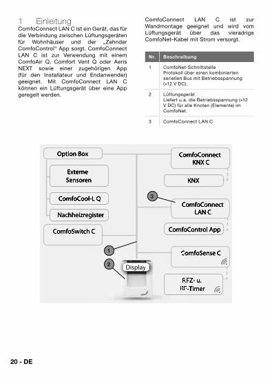
1 EinleitungComfoConnect LAN C ist ein Gerät, das für die Verbindung zwischen Lüftungsgeräten für Wohnhäuser und der „Zehnder ComfoControl“ App sorgt. ComfoConnect LAN C ist zur Verwendung mit einem ComfoAir Q, Comfort Vent Q oder Aeris NEXT sowie einer zugehörigen App (für den Installateur und Endanwender) geeignet. Mit ComfoConnect LAN C können ein Lüftungsgerät über eine App geregelt werden.
ComfoConnect LAN C ist zur Wandmontage geeignet und wird vom Lüftungsgerät über das vieradrige ComfoNet-Kabel mit Strom versorgt.
Nr. Beschreibung
1 ComfoNet-SchnittstelleProtokoll über einen kombinierten seriellen Bus mit Betriebsspannung (+12 V DC).
2 LüftungsgerätLiefert u.a. die Betriebsspannung (+12 V DC) für alle Knoten (Elemente) im ComfoNet.
3 ComfoConnect LAN C
KNX
ComfoControl App
ComfoConnectLAN C
ComfoConnect KNX C
ComfoCool-L Q
Nachheizregister
Externe Sensoren
Option Box
RFZ- u. RFZ- u. RF-TimerRF-Timer
ComfoSense CComfoSense C
ComfoSwitch C
Display
1
2
3
21 - DE
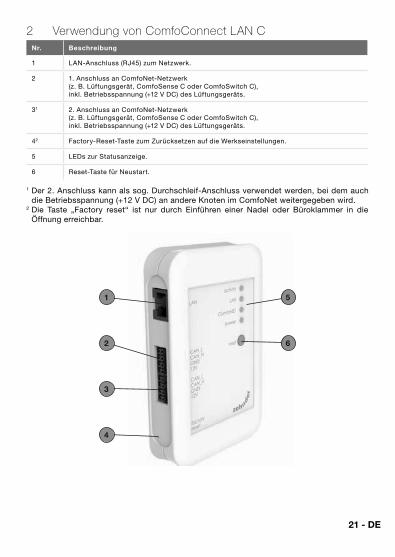
2 Verwendung von ComfoConnect LAN CNr. Beschreibung
1 LAN-Anschluss (RJ45) zum Netzwerk.
2 1. Anschluss an ComfoNet-Netzwerk (z. B. Lüftungsgerät, ComfoSense C oder ComfoSwitch C), inkl. Betriebsspannung (+12 V DC) des Lüftungsgeräts.
31 2. Anschluss an ComfoNet-Netzwerk (z. B. Lüftungsgerät, ComfoSense C oder ComfoSwitch C), inkl. Betriebsspannung (+12 V DC) des Lüftungsgeräts.
42 Factory-Reset-Taste zum Zurücksetzen auf die Werkseinstellungen.
5 LEDs zur Statusanzeige.
6 Reset-Taste für Neustart.
1 Der 2. Anschluss kann als sog. Durchschleif-Anschluss verwendet werden, bei dem auch die Betriebsspannung (+12 V DC) an andere Knoten im ComfoNet weitergegeben wird.
2 Die Taste „Factory reset“ ist nur durch Einführen einer Nadel oder Büroklammer in die Öffnung erreichbar.
1
2
5
6
3
4
22 - DE
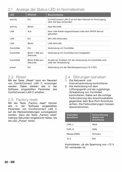
2.1 Anzeige der Status-LED im Normalbetrieb LED STATUS Beschreibung
activity Ein ComfoConnect LAN C ist mit dem Internet für Fernzugang über die App verbunden.
activity Blinkt App-Aktivität.
LAN Aus Kein LAN-Kabel angeschlossen oder kein DHCP-Server gefunden.
LAN Ein Mit LAN verbunden.
LAN Blinkt LAN-Aktivität.
ComfoNet Ein Verbindung mit ComfoNet.
ComfoNet Blinkt 1 Mal pro Sekunde
Verbindung mit ComfoNet wird hergestellt.
ComfoNet Blinkt 8 Mal pro Sekunde
Es gibt ein Problem mit der Verbindung mit ComfoNet und/oder der Verkabelung.
power Ein Verbindung mit der Betriebsspannung (+12 V DC).
2.2 ResetMit der Taste „Reset“ kann ein Neustart von ComfoConnect LAN C erzwungen werden. Dabei bleiben alle in der Software eingestellten Parameter des ComfoConnect LAN C erhalten.
2.3 Factory resetMit der Taste „Factory reset“ können alle in der Software eingestellten Parameter von ComfoConnect LAN C auf die Werkseinstellungen zurückgesetzt werden. Dazu die Taste „Factory reset“ mehrere Sekunden eingedrückt halten, bis die LED „Power“ blinkt.
2.4 Störungen beheben1. Die Netzwerk- und
Internetverbindung kontrollieren.2. Die Verbindung mit dem
Lüftungsgerät und die zugehörige Verkabelung von ComfoNet kontrollieren. Dabei auf die richtige Farbcodierung des Anschlusskabels gegenüber dem Bus-Port-Anschluss achten. Die Farbcodierungen müssen übereinstimmen.
ComfoNet-Anschluss
Farbcodierung (Kabel und Anschluss)
CAN_L Weiß
CAN_H Gelb
Masse (GND) Schwarz
12 V Rot
Kontrollieren, ob die Spannung von +12 V DC vorhanden ist.

23 - DE
3 Technische DatenElektrisch
Nenn-Eingangsspannung +12 V DC
Eingangsspannungsbereich 12 V DC +/- 20 %
Nenn-Eingangsstrom 0,06 A
Galvanische Trennung 1500 V AC (60 Sek.)
Nenn-Leistungsaufnahme 0,72 W
Maximale Leistungsaufnahme 1,00 W
Maximaler Durchschleifstrom 3,20 A
Umgebung
Betriebstemperatur -20 °C bis +60 °C
Lagerungs- und Transporttemperatur -40°C bis +80°C
Luftfeuchtigkeit < 95 %
Schutzart IP-Klasse 30 Verschmutzungsgrad PD3 (Heizungsraum)
Brennbarkeitsklasse Anschlüsse UL 94 V0
Brennbarkeitsklasse Gehäuse UL 94 HB (< 20J)
Brennbarkeitsklasse Platine UL 94 V0
Gehäusematerial ABS
Gewicht 90 Gramm
Standard
Sicherheit EN60950-1
Elektromagnetische Verträglichkeit (EMV) CISPR22, EN61000-6-3, EN61000-6-1, EN50491-5-1, EN50491-5-2
Anforderungen an Umweltschutz RoHS, REACH,WEEE
Software
LAN IPv4 mit DHCP oder AUTOIP
Umfasst eine MatrixSSLTM Security Softwarelizenz von INSIDE Secure
24 - DE
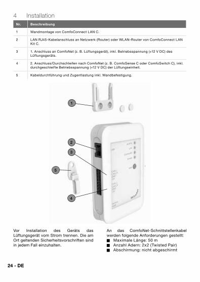
4 InstallationNr. Beschreibung
1 Wandmontage von ComfoConnect LAN C.
2 LAN RJ45-Kabelanschluss an Netzwerk (Router) oder WLAN-Router von ComfoConnect LAN Kit C.
3 1. Anschluss an ComfoNet (z. B. Lüftungsgerät), inkl. Betriebsspannung (+12 V DC) des Lüftungsgeräts.
4 2. Anschluss/Durchschleifen nach ComfoNet (z. B. ComfoSense C oder ComfoSwitch C), inkl. durchgeschleifte Betriebsspannung (+12 V DC) der Lüftungseinheit.
5 Kabeldurchführung und Zugentlastung inkl. Wandbefestigung.
1
2
5
3
4
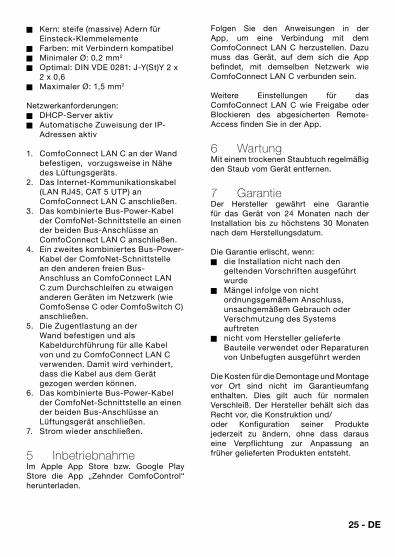
Vor Installation des Geräts das Lüftungsgerät vom Strom trennen. Die am Ort geltenden Sicherheitsvorschriften sind in jedem Fall einzuhalten.
An das ComfoNet-Schnittstellenkabel werden folgende Anforderungen gestellt:� Maximale Länge: 50 m� Anzahl Adern: 2x2 (Twisted Pair)� Abschirmung: nicht abgeschirmt
25 - DE
� Kern: steife (massive) Adern für Einsteck-Klemmelemente
� Farben: mit Verbindern kompatibel� Minimaler Ø: 0,2 mm2
� Optimal: DIN VDE 0281: J-Y(St)Y 2 x 2 x 0,6
� Maximaler Ø: 1,5 mm2
Netzwerkanforderungen:� DHCP-Server aktiv� Automatische Zuweisung der IP-
Adressen aktiv
1. ComfoConnect LAN C an der Wand befestigen, vorzugsweise in Nähe des Lüftungsgeräts.
2. Das Internet-Kommunikationskabel (LAN RJ45, CAT 5 UTP) an ComfoConnect LAN C anschließen.
3. Das kombinierte Bus-Power-Kabel der ComfoNet-Schnittstelle an einen der beiden Bus-Anschlüsse an ComfoConnect LAN C anschließen.
4. Ein zweites kombiniertes Bus-Power-Kabel der ComfoNet-Schnittstelle an den anderen freien Bus-Anschluss an ComfoConnect LAN C zum Durchschleifen zu etwaigen anderen Geräten im Netzwerk (wie ComfoSense C oder ComfoSwitch C) anschließen.
5. Die Zugentlastung an der Wand befestigen und als Kabeldurchführung für alle Kabel von und zu ComfoConnect LAN C verwenden. Damit wird verhindert, dass die Kabel aus dem Gerät gezogen werden können.
6. Das kombinierte Bus-Power-Kabel der ComfoNet-Schnittstelle an einen der beiden Bus-Anschlüsse an Lüftungsgerät anschließen.
7. Strom wieder anschließen.
5 InbetriebnahmeIm Apple App Store bzw. Google Play Store die App „Zehnder ComfoControl“ herunterladen.
Folgen Sie den Anweisungen in der App, um eine Verbindung mit dem ComfoConnect LAN C herzustellen. Dazu muss das Gerät, auf dem sich die App befindet, mit demselben Netzwerk wie ComfoConnect LAN C verbunden sein.
Weitere Einstellungen für das ComfoConnect LAN C wie Freigabe oder Blockieren des abgesicherten Remote-Access finden Sie in der App.
6 WartungMit einem trockenen Staubtuch regelmäßig den Staub vom Gerät entfernen.
7 GarantieDer Hersteller gewährt eine Garantie für das Gerät von 24 Monaten nach der Installation bis zu höchstens 30 Monaten nach dem Herstellungsdatum.
Die Garantie erlischt, wenn:� die Installation nicht nach den
geltenden Vorschriften ausgeführt wurde
� Mängel infolge von nicht ordnungsgemäßem Anschluss, unsachgemäßem Gebrauch oder Verschmutzung des Systems auftreten
� nicht vom Hersteller gelieferte Bauteile verwendet oder Reparaturen von Unbefugten ausgeführt werden
Die Kosten für die Demontage und Montage vor Ort sind nicht im Garantieumfang enthalten. Dies gilt auch für normalen Verschleiß. Der Hersteller behält sich das Recht vor, die Konstruktion und/oder Konfiguration seiner Produkte jederzeit zu ändern, ohne dass daraus eine Verpflichtung zur Anpassung an früher gelieferten Produkten entsteht.
26 - FR
Avant-propos Lisez attentivement ce manuel avant utilisation.
Il contient toutes les informations supplémentaires pour une installation, commande et maintenance sûres et optimales du ComfoConnect LAN C (dénommé ci-après « l'unité »). L'unité est soumise à une amélioration et un développement continus. Il est donc possible que l'unité dévie légèrement des descriptions.
QuestionsSi vous avez des questions, contactez le fournisseur. Au dos de ce manuel, vous trouverez une liste avec les coordonnées des principaux fournisseurs.
Dangers électriquesPendant l'installation ou les travaux de maintenance, il existe des risques de chocs électriques. Observez toujours les consignes de sécurité contenues dans ce manuel. Le non-respect des consignes de sécurité, mises en garde, remarques et instructions peut entraîner des blessures corporelles ainsi que des dommages à l'unité. Mettez le ComfoAir Q, le Comfort Vent Q ou l'Aeris NEXT (dénommé ci-après « l'unité de ventilation ») hors tension avant de connecter ou déconnecter quoi que ce soit à l'appareil.
Tous droits réservés.Le présent document a été rédigé avec le plus grand soin. L'éditeur ne peut néanmoins pas être tenu responsable de dommages découlant d'informations manquantes ou erronées dans le présent document. En cas de différend, le texte néerlandais prévaut.
FR - 27
Table des matières Avant-propos ............................................................................................. 26
1 Introduction ............................................................................................... 28
2 Utilisation du ComfoControl LAN C ............................................................. 29
2.1 Voyant lumineux lors d'une utilisation normale ...................................... 30
2.2. Réinitialisation ..................................................................................... 30
2.3 Factory reset (réinitialisation aux paramètres d'usine) ............................ 30
2.4 Réinitialisation des défauts .................................................................. 30
3 Spécifications techniques .......................................................................... 31
4 Installation ................................................................................................. 32
5 Mise en service ......................................................................................... 33
6 Maintenance ............................................................................................. 33
7 Garantie .................................................................................................... 33
28 - FR
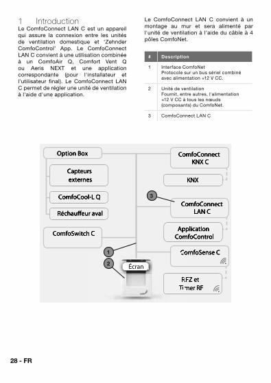
1 IntroductionLe ComfoConnect LAN C est un appareil qui assure la connexion entre les unités de ventilation domestique et ‘Zehnder ComfoControl’ App. Le ComfoConnect LAN C convient à une utilisation combinée à un ComfoAir Q, Comfort Vent Q ou Aeris NEXT et une application correspondante (pour l'installateur et l'utilisateur final). Le ComfoConnect LAN C permet de régler une unité de ventilation à l'aide d'une application.
Le ComfoConnect LAN C convient à un montage au mur et sera alimenté par l'unité de ventilation à l'aide du câble à 4 pôles ComfoNet.
# Description
1 Interface ComfoNetProtocole sur un bus sériel combiné avec alimentation +12 V CC.
2 Unité de ventilationFournit, entre autres, l'alimentation +12 V CC à tous les nœuds (composants) du ComfoNet.
3 ComfoConnect LAN C
KNX
Application ComfoControl
ComfoConnectLAN C
ComfoConnect KNX C
ComfoCool-L Q
Réchauffeur aval
Capteurs externes
Option Box
RFZ et RFZ et Timer RFTimer RF
ComfoSense CComfoSense C
ComfoSwitch C
Écran
1
2
3
FR - 29
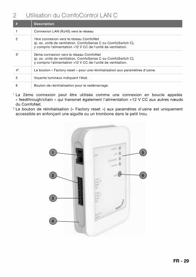
2 Utilisation du ComfoControl LAN C# Description
1 Connexion LAN (RJ45) vers le réseau
2 1ère connexion vers le réseau ComfoNet (p. ex. unité de ventilation, ComfoSense C ou ComfoSwitch C), y compris l'alimentation +12 V CC de l'unité de ventilation.
31 2ème connexion vers le réseau ComfoNet (p. ex. unité de ventilation, ComfoSense C ou ComfoSwitch C), y compris l'alimentation +12 V CC de l'unité de ventilation.
42 Le bouton « Factory reset » pour une réinitialisation aux paramètres d'usine.
5 Voyants lumineux indiquant l'état.
6 Bouton de réinitialisation pour le redémarrage.
1 La 2ème connexion peut être utilisée comme une connexion en boucle appelée « feedthrough/chain » qui transmet également l'alimentation +12 V CC aux autres nœuds du ComfoNet.
2 Le bouton de réinitialisation (« Factory reset ») aux paramètres d'usine est uniquement accessible en enfonçant une aiguille ou un trombone dans le petit trou.
1
2
5
6
3
4
30 - FR
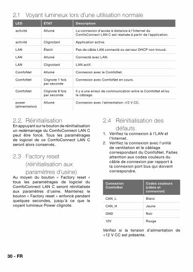
2.1 Voyant lumineux lors d'une utilisation normale LED ÉTAT Description
activité Allumé La connexion d'accès à distance à l'Internet du ComfoConnect LAN C est réalisée à partir de l'application.
activité Clignotant Application active.
LAN Éteint Pas de câble LAN connecté ou serveur DHCP non trouvé.
LAN Allumé Connecté avec LAN.
LAN Clignotant LAN actif.
ComfoNet Allumé Connexion avec le ComfoNet.
ComfoNet Clignote 1 fois par seconde
Connexion avec ComfoNet en cours.
ComfoNet Clignote 8 fois par seconde
Il y a une erreur de communication entre le ComfoNet et/ou le câblage.
power (alimentation)
Allumé Connexion avec l'alimentation +12 V CC.
2.2. RéinitialisationEn appuyant sur le bouton de réinitialisation un redémarrage du ComfoConnect LAN C peut être forcé. Tous les paramétrages de logiciel de ce ComfoConnect LAN C seront alors conservés.
2.3 Factory reset (réinitialisation aux paramètres d'usine)
Au moyen du bouton « Factory reset » tous les paramétrages de logiciel du ComfoConnect LAN C seront réinitialisés aux paramètres d'usine. Maintenez le bouton « Factory reset » enfoncé pendant quelques secondes, jusqu'à ce que le voyant lumineux Power clignote.
2.4 Réinitialisation des défauts
1. Vérifiez la connexion à l‘LAN et l‘Internet.
2. Vérifiez la connexion avec l'unité de ventilation et le câblage correspondant du ComfoNet. Faites attention aux codes couleurs du câble de connexion par rapport à la connexion port bus qui doivent correspondre.
Connexion ComfoNet
Codes couleurs (câble et connexion)
CAN_L Blanc
CAN_H Jaune
GND Noir
12V Rouge
Vérifiez si la tension d'alimentation de +12 V CC est présente.
FR - 31
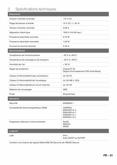
3 Spécifications techniquesElectricité
Tension d'entrée nominale +12 V CC
Plage de tension d'entrée 12 V CC +/- 20 %
Tension d'entrée nominale 0,06 A
Séparation électrique 1500 V CA (60 sec.)
Puissance absorbée nominale 0,72 W
Puissance absorbée maximale 1,00 W
Courant en boucle maximal 3,20 A
Environnement
Température de fonctionnement -20°C à +60°C
Température de stockage et de transport -40°C à +80°C
Humidité de l'air < 95 %
Degré de protection Classe IP 30 Degré d'encrassement PD3 (chaufferie)
Classe d'inflammabilité des connecteurs UL 94 V0
Classe d'inflammabilité de l'enveloppe UL 94 HB (< 20J)
Classe d'inflammabilité du circuit imprimé UL 94 V0
Matériel de l'enveloppe ABS
Poids 90 grammes
Standard
Sécurité EN60950-1
Compatibilité électromagnétique (CEM) CISPR22, EN61000-6-3, EN61000-6-1, EN50491-5-1, EN50491-5-2
Exigences relatives à l'environnement RoHS, REACH,WEEE
Logiciel
LAN IPv4 avec DHCP ou AUTOIP
Contient une licence de logiciel MatrixSSLTM Security de INSIDE Secure
32 - FR
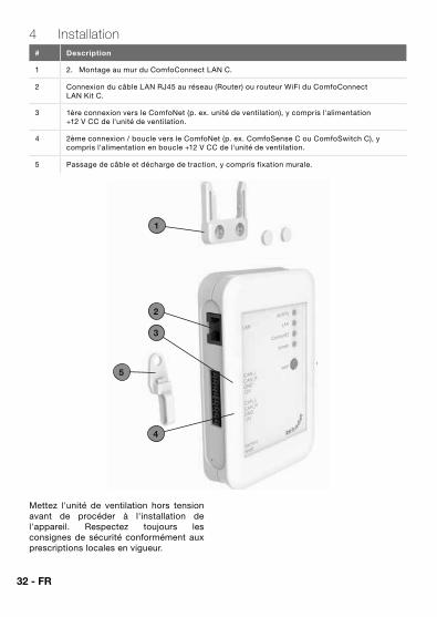
4 Installation# Description
1 2. Montage au mur du ComfoConnect LAN C.
2 Connexion du câble LAN RJ45 au réseau (Router) ou routeur WiFi du ComfoConnect LAN Kit C.
3 1ère connexion vers le ComfoNet (p. ex. unité de ventilation), y compris l'alimentation +12 V CC de l'unité de ventilation.
4 2ème connexion / boucle vers le ComfoNet (p. ex. ComfoSense C ou ComfoSwitch C), y compris l'alimentation en boucle +12 V CC de l'unité de ventilation.
5 Passage de câble et décharge de traction, y compris fixation murale.
1
2
5
3
4
Mettez l'unité de ventilation hors tension avant de procéder à l'installation de l'appareil. Respectez toujours les consignes de sécurité conformément aux prescriptions locales en vigueur.
FR - 33
Les exigences relatives au câble de l'interface de ComfoNet sont les suivantes :� Longueur maximale : 50 m ;� Nombre de brins : 2x2 (paire
torsadée) ;� Blindage : non blindé ;� Noyau : fils (pleins) rigides pour
éléments de bornes à insérer ;� Couleurs : compatibles avec les
connecteurs ;� Ø minimal : 0,2 mm2 ;� Optimal : DIN VDE 0281 : J-Y(St)Y 2 x
2 x 0,6� Ø maximal : 1,5 mm2 .
Les exigences de réseau sont :� Serveur DHCP actif ;� Attribution automatique d’adresse IP
active.
1. Fixez le ComfoConnect LAN C au mur, de préférence à proximité de l'unité de ventilation.
2. Connectez le câble de communication avec l'Internet (LAN ; RJ45, CAT 5 UTP) au ComfoConnect LAN C.
3. Connectez le câble combiné bus-Power (alimentation) de l'interface du ComfoNet à l'un des deux ports bus du ComfoConnect LAN C.
4. Connectez un deuxième câble combiné bus-Power (alimentation) de l'interface du ComfoNet à l'autre port bus disponible du ComfoConnect LAN C, pour la connexion en boucle vers d'éventuels autres appareils du réseau, comme un ComfoSense C ou un ComfoSwitch C.
5. Fixez la décharge de traction au mur et utilisez-la comme passage de câble pour l'ensemble des câbles en provenance et en direction du ComfoConnect LAN C. Celle-ci permet d'éviter que les câbles puissent être retirés de l'appareil en les tirant.
5 Mise en serviceTéléchargez l'application ‘Zehnder ComfoControl’ à partir de d'Apple App Store ou de Google Play Store.
Suivez les instructions contenues dans l’Application pour établir une connexion avec le ComfoConnect LAN C. Pour cela, l’appareil sur lequel l’Application est installée doit être connecté au même réseau que le ComfoConnect LAN C.
Les autres paramètres du ComfoConnect LAN C, tels que l’autorisation ou le blocage de l’accès à distance sécurisé, sont disponibles dans l’application.
6 MaintenanceÉliminez régulièrement la poussière de l'unité à l'aide d'un chiffon sec.
7 GarantieLe fabricant accorde une garantie applicable à l'unité pour une période allant de 24 mois après l'installation jusqu'à un maximum de 30 mois après la date de fabrication.
La garantie est annulée si :� l'installation n'a pas été effectuée
suivant les instructions en vigueur ;� les défauts sont dus à un mauvais
raccordement, à une utilisation incompétente ou à l'encrassement du système ;
� des pièces qui n'ont pas été livrées par le fabricant ont été utilisées ou si des réparations sont exécutées par des personnes non autorisées .
Les frais de montage et de démontage sur place sont exclus des conditions de garantie. Ceci est également valable pour une usure normale. Le fabricant se réserve le droit de modifier la construction et/ou la configuration de ses produits à tout moment sans l'obligation d'adapter des produits déjà fournis.
34 - IT
Premessa Leggere attentamente il presente manuale prima dell'utilizzo del prodotto.
Il presente documento fornisce tutte le informazioni integrative necessarie ad assicurare un funzionamento, un'installazione e una manutenzione ottimali e sicuri del ComfoConnect LAN C (di seguito "l'unità"). L'unità è soggetta a continui sviluppi e miglioramenti. Pertanto, è possibile che differisca lievemente dalla descrizione fornita.
Dubbi o richiesteIn caso di dubbi o richieste contattare il fornitore L'ultima pagina del presente manuale contiene un elenco con i dati per contattare i principali fornitori.
Rischi elettriciDurante l'installazione o nel corso degli interventi di manutenzione sussiste il rischio di scossa elettrica. Rispettare sempre le norme di sicurezza contenute in questo manuale. Il mancato rispetto delle norme di sicurezza, di avvertenze, commenti e istruzioni potrebbe provocare lesioni personali o danni all'unità. Staccare la corrente dal ComfoAir Q, Comfort Vent Q o Aeris NEXT (di seguito “unità di ventilazione”) prima di collegare o scollegare qualsiasi cosa all'apparecchio.
Tutti i diritti riservati.Questo documento è stato redatto con la massima cura e attenzione. L'editore non può comunque essere ritenuto responsabile di eventuali danni derivanti dalla mancanza o dall'inesattezza delle informazioni qui fornite. In caso di controversie, farà fede il testo in neerlandese.
IT - 35
Sommario Premessa .................................................................................................. 34
1 Introduzione .............................................................................................. 36
2 Utilizzo del ComfoConnect LAN C .............................................................. 37
2.1 LED di indicazione di stato durante il normale utilizzo ........................... 38
2.2 Reset ................................................................................................. 38
2.3 Factory reset....................................................................................... 38
2.4 Risoluzione guasti ............................................................................... 38
3 Dati tecnici ................................................................................................ 39
4 Installazione .............................................................................................. 40
5 Messa in funzione ...................................................................................... 41
6 Manutenzione ............................................................................................ 41
7 Garanzia ................................................................................................... 41
36 - IT
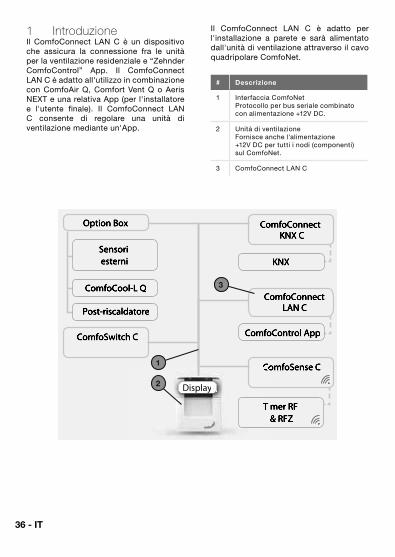
1 IntroduzioneIl ComfoConnect LAN C è un dispositivo che assicura la connessione fra le unità per la ventilazione residenziale e “Zehnder ComfoControl” App. Il ComfoConnect LAN C è adatto all'utilizzo in combinazione con ComfoAir Q, Comfort Vent Q o Aeris NEXT e una relativa App (per l'installatore e l'utente finale). Il ComfoConnect LAN C consente di regolare una unità di ventilazione mediante un'App.
Il ComfoConnect LAN C è adatto per l'installazione a parete e sarà alimentato dall'unità di ventilazione attraverso il cavo quadripolare ComfoNet.
# Descrizione
1 Interfaccia ComfoNetProtocollo per bus seriale combinato con alimentazione +12V DC.
2 Unità di ventilazioneFornisce anche l'alimentazione +12V DC per tutti i nodi (componenti) sul ComfoNet.
3 ComfoConnect LAN C
KNX
ComfoControl App
ComfoConnectLAN C
ComfoConnect KNX C
ComfoCool-L Q
Post-riscaldatore
Sensori esterni
Option Box
Timer RF Timer RF & RFZ
ComfoSense CComfoSense C
ComfoSwitch C
Display
1
2
3
IT - 37
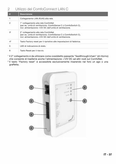
2 Utilizzo del ComfoConnect LAN C# Descrizione
1 Collegamento LAN (RJ45) alla rete.
2 1° collegamento alla rete ComfoNet (per es. unità di ventilazione, ComfoSense C o ComfoSwitch C), incl. alimentazione +12V DC dell'unità di ventilazione.
31 2° collegamento alla rete ComfoNet (per es. unità di ventilazione, ComfoSense C o ComfoSwitch C), incl. alimentazione +12V DC dell'unità di ventilazione.
42 Tasto Factory reset per il ripristino alle impostazioni di fabbrica.
5 LED di indicazione di stato.
6 Tasto Reset per il riavvio.
1 Il 2° collegamento è da utilizzare come cosiddetto passante "feedthrough/chain" (di ritorno) che consente di trasferire anche l'alimentazione +12V DC ad altri nodi sul ComfoNet.
2 Il tasto "Factory reset" è accessibile esclusivamente inserendo nel foro un ago o una graffetta.
1
2
5
6
3
4
38 - IT
2.1 LED di indicazione di stato durante il normale utilizzo LED STATO Descrizione
activity Acceso Il ComfoConnect LAN C è collegato a internet per l'accesso remoto mediante l'App.
activity Lampeggia Attività App.
LAN Spento Nessun collegamento cavo LAN o server DHCP trovato.
LAN Acceso Collegamento LAN.
LAN Lampeggia Attività LAN.
ComfoNet Acceso Connessione con il ComfoNet.
ComfoNet Lampeggia 1x al secondo
Connessione in corso con il ComfoNet.
ComfoNet Lampeggia 8x al secondo
C'è un problema con la connessione al ComfoNet e/o con i cavi.
power Acceso Connessione con l'alimentazione +12V DC.
2.2 ResetIl tasto Reset consente di forzare un riavvio del ComfoConnect LAN C che conserverà tutti i parametri impostati in modalità software.
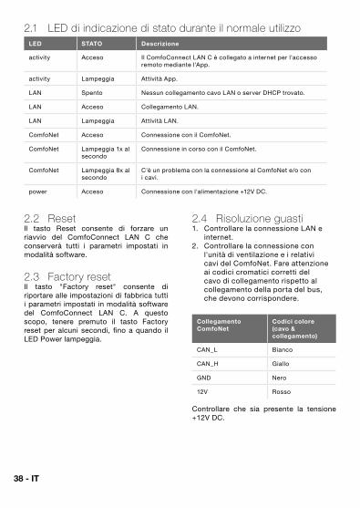
2.3 Factory resetIl tasto "Factory reset" consente di riportare alle impostazioni di fabbrica tutti i parametri impostati in modalità software del ComfoConnect LAN C. A questo scopo, tenere premuto il tasto Factory reset per alcuni secondi, fino a quando il LED Power lampeggia.
2.4 Risoluzione guasti1. Controllare la connessione LAN e
internet.2. Controllare la connessione con
l'unità di ventilazione e i relativi cavi del ComfoNet. Fare attenzione ai codici cromatici corretti del cavo di collegamento rispetto al collegamento della porta del bus, che devono corrispondere.
Collegamento ComfoNet
Codici colore (cavo & collegamento)
CAN_L Bianco
CAN_H Giallo
GND Nero
12V Rosso
Controllare che sia presente la tensione +12V DC.
IT - 39
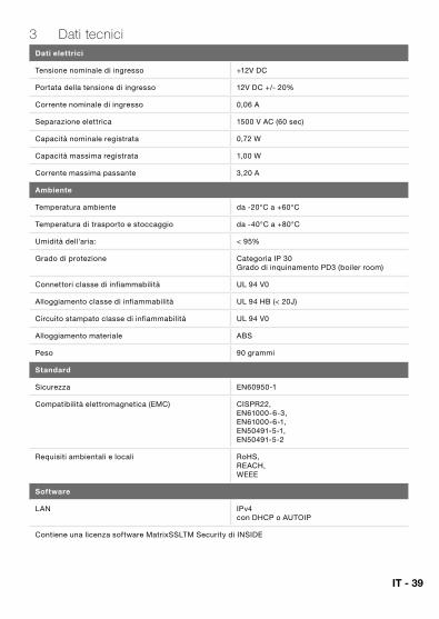
3 Dati tecniciDati elettrici
Tensione nominale di ingresso +12V DC
Portata della tensione di ingresso 12V DC +/- 20%
Corrente nominale di ingresso 0,06 A
Separazione elettrica 1500 V AC (60 sec)
Capacità nominale registrata 0,72 W
Capacità massima registrata 1,00 W
Corrente massima passante 3,20 A
Ambiente
Temperatura ambiente da -20°C a +60°C
Temperatura di trasporto e stoccaggio da -40°C a +80°C
Umidità dell'aria: < 95%
Grado di protezione Categoria IP 30 Grado di inquinamento PD3 (boiler room)
Connettori classe di infiammabilità UL 94 V0
Alloggiamento classe di infiammabilità UL 94 HB (< 20J)
Circuito stampato classe di infiammabilità UL 94 V0
Alloggiamento materiale ABS
Peso 90 grammi
Standard
Sicurezza EN60950-1
Compatibilità elettromagnetica (EMC) CISPR22, EN61000-6-3, EN61000-6-1, EN50491-5-1, EN50491-5-2
Requisiti ambientali e locali RoHS, REACH,WEEE
Software
LAN IPv4 con DHCP o AUTOIP
Contiene una licenza software MatrixSSLTM Security di INSIDE
40 - IT
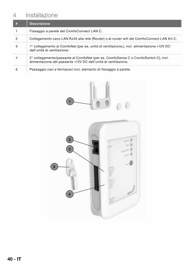
4 Installazione# Descrizione
1 Fissaggio a parete del ComfoConnect LAN C.
2 Collegamento cavo LAN RJ45 alla rete (Router) o al router wifi del ComfoConnect LAN Kit C.
3 1° collegamento al ComfoNet (per es. unità di ventilazione,), incl. alimentazione +12V DC dell'unità di ventilazione.
4 2° collegamento/passante al ComfoNet (per es. ComfoSense C o ComfoSwitch C), incl. alimentazione del passante +12V DC dell'unità di ventilazione.
5 Passaggio cavi e fermacavi incl. elemento di fissaggio a parete.
1
2
5
3
4
IT - 41
Staccare la corrente dall'unità di ventilazione prima di installare l'apparecchio. Rispettare sempre le indicazioni di sicurezza locali in vigore.
I requisiti del cavo per il cavo dell'interfaccia ComfoNet sono:� Lunghezza massima: 50m� Numero fili: 2x2 (twisted pair);� Schermatura: non schermato;� Anima: fili rigidi (pieni) per elementi
da inserimento;� Colori: compatibili con i connettori;� Ø minimo: 0,2 mm2;� Ottimale: DIN VDE 0281: J-Y(St)Y 2 x
2 x 0,6� Ø massimo: 1,5 mm2.
I requisiti di rete sono:� Server DHCP attivo;� Rilascio indirizzo IP automatico
attivo.
1. Fissare il ComfoConnect LAN C alla parete. Preferibilmente nelle vicinanze dell'unità di ventilazione.
2. Collegare il cavo di comunicazione internet (LAN; RJ45, CAT 5 UTP) al ComfoConnect LAN C.
3. Collegare il cavo combinato bus-Power dell'interfaccia ComfoNet a una delle due porte bus sul ComfoConnect LAN C.
4. Collegare un secondo cavo combinato bus-Power dell'interfaccia ComfoNet sull'altra porta bus disponibile sul ComfoConnect LAN C, per il collegamento agli altri eventuali apparecchi nella rete, come ComfoSense C, ComfoSwitch C.
5. Fissare il fermacavi alla parete e utilizzarlo come passacavi per tutti i cavi in entrata e in uscita dal ComfoConnect LAN C. In questo modo si evita che i cavi possano essere tirati.
6. Collegare il cavo combinato bus-Power dell‘interfaccia ComfoNet a una delle due porte bus sul unita di ventilazione.
7. Attivare l‘alimentazione.
5 Messa in funzioneScaricare l'App "Zehnder ComfoControl" dall'Apple App Store o da Google Play Store.
Seguire le istruzioni nell’App per creare la connessione con il ComfoConnect LAN C. A questo scopo il dispositivo su cui gira l’app deve essere connesso alla stessa rete del ComfoConnect LAN C.
Altre impostazioni del ComfoConnect LAN C come il blocco o lo sblocco dell’accesso remoto sicuro si possono trovare nell’app.
6 ManutenzioneRimuovere regolarmente la polvere dall'unità con un apposito panno asciutto.
7 GaranziaL'unità è coperta da una garanzia rilasciata dal costruttore per un periodo di 24 mesi dall’installazione, fino ad un massimo di 30 mesi dalla data di fabbricazione.
La garanzia decade se:� l'installazione non è stata eseguita
secondo le disposizioni vigenti;� si sono verificati difetti a seguito
di allacciamento non corretto, utilizzo incompetente o sporcizia dell'impianto;
� sono stati utilizzati ricambi non forniti dal costruttore o sono state eseguite riparazioni da parte di personale non competente.
La garanzia non copre i costi di installazione e smontaggio sul posto. La garanzia non copre neppure la normale usura. Il costruttore si riserva il diritto di modificare la costruzionee/o la configurazione dei suoi prodotti in qualsiasi momento senza essere tenuto a modificare i prodotti precedentemente forniti.
42 - PL
Przedmowa Przed użyciem urządzenia należy dokładnie zapoznać się z treścią niniejszego dokumentu.
Niniejszy dokument zawiera dodatkowe informacje dotyczące bezpiecznego i optymalnego montażu, obsługi i konserwacji urządzenia ComfoConnect LAN C (nazywanego dalej „urządzeniem”). Urządzenie jest rozwijane i ulepszane w sposób ciągły. Dlatego też może nieco różnić się od przedstawionych tu opisów.
ZapytaniaWszelkie pytania należy kierować do dostawcy urządzenia. Na tylnej okładce instrukcji znajdują się dane kontaktowe głównych dostawców.
Zagrożenia elektrycznePodczas wykonywania czynności instalacyjnych lub konserwacyjnych występuje zagrożenie porażeniem prądem elektrycznym. Należy stosować się do przepisów dotyczących bezpieczeństwa zawartych w niniejszej instrukcji obsługi. Niestosowanie się do przepisów dotyczących bezpieczeństwa, ostrzeżeń, komentarzy i uwag umieszczonych w niniejszym dokumencie, może doprowadzić do obrażeń ciała lub uszkodzeń urządzenia. Przed podłączeniem czegokolwiek do lub odłączeniem czegokolwiek od urządzenia, należy odłączyć zasilanie ComfoAir Q, Comfort Vent Q lub Aeris NEXT (dalej nazywane „jednostką wentylacyjną”).
Wszelkie prawa zastrzeżone.Niniejsza instrukcja obsługi została sporządzona z najwyższą starannością. Jednakże wydawca nie ponosi odpowiedzialności za jakiekolwiek szkody powstałe na skutek nieumieszczenia w niej informacji lub umieszczenia w niej nieprawidłowych informacji. W przypadku wystąpienia rozbieżności, wiążący jest teks w języku niderlandzkim.
PL - 43
Spis treściPrzedmowa ................................................................................................... 42
1 Wprowadzenie ........................................................................................... 44
2 Korzystanie z ComfoConnect LAN C .......................................................... 45
2.1 Status wskaźnika diodowego podczas normalnego użytkowania ............ 46
2.2 Resetowanie ....................................................................................... 46
2.3 Wyzerowanie do ustawień fabrycznych ................................................ 46
2.4 Usuwanie usterek................................................................................ 46
3 Specyfikacje techniczne ............................................................................ 47
4 Montaż...................................................................................................... 48
5 Procedury uruchomienia ............................................................................ 49
6 Konserwacja ............................................................................................. 49
7 Gwarancja ................................................................................................. 49
44 - PL
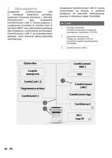
1 WprowadzenieUrządzenie ComfoConnect LAN C nawiązuje połączenie pomiędzy systemem domowej wentylacji i „Zehnder ComfoControl” App. Urządzenie ComfoConnect LAN C można połączyć z urządzeniem ComfoAir Q, Comfort Vent Q lub Aeris NEXT oraz odpowiednią aplikacją (dla instalatora i użytkownika końcowego). ComfoConnect LAN C za pośrednictwem aplikacji, może sterować jedną jednostką wentylacyjną.
Urządzenie ComfoConnect LAN C można zamontować na ścianie, a zasilanie podłączyć do jednostki wentylacyjnej, poprzez 4-rdzeniowy kabel ComfoNet.
Nr Opis
1 Interfejs ComfoNetProtokół uniwersalnej magistrali szeregowej z zasilaniem +12V DC.
2 Jednostka wentylacyjnaPodaje np. zasilanie +12V do wszystkich węzłów (podzespołów) ComfoNet.
3 ComfoConnect LAN C
KNX
ComfoControl App
ComfoConnectLAN C
ComfoConnect KNX C
ComfoCool-L Q
Nagrzewnica wtórna
Czujniki zewnętrzne
Option Box
RFZ i timer RFtimer RF
ComfoSense CComfoSense C
ComfoSwitch C
Wyświetlacz
1
2
3
PL - 45
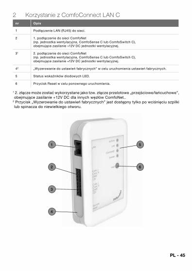
2 Korzystanie z ComfoConnect LAN Cnr Opis
1 Podłączenie LAN (RJ45) do sieci.
2 1. podłączenie do sieci ComfoNet (np. jednostka wentylacyjna, ComfoSense C lub ComfoSwitch C), obejmujące zasilanie +12V DC jednostki wentylacyjnej.
31 2. podłączenie do sieci ComfoNet (np. jednostka wentylacyjna, ComfoSense C lub ComfoSwitch C), obejmujące zasilanie +12V DC jednostki wentylacyjnej.
42 „Wyzerowanie do ustawień fabrycznych” w celu uruchomienia ustawień fabrycznych.
5 Status wskaźników diodowych LED.
6 Przycisk Reset w celu ponownego uruchomienia.
1 2. złącze może zostać wykorzystane jako tzw. złącze przelotowe „przejściowe/łańcuchowe”, obejmujące zasilanie +12V DC dla innych węzłów ComfoNet..
2 Przycisk „Wyzerowanie do ustawień fabrycznych” jest dostępny tylko po wciśnięciu szpilki lub spinacza do niewielkiego otworu.
1
2
5
6
3
4
46 - PL
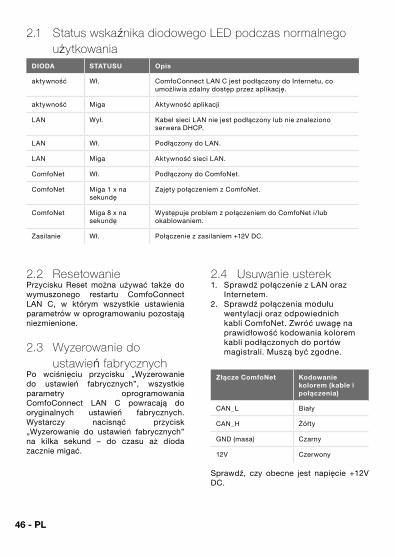
2.1 Status wskaźnika diodowego LED podczas normalnego użytkowania
DIODA STATUSU Opis
aktywność Wł. ComfoConnect LAN C jest podłączony do Internetu, co umożliwia zdalny dostęp przez aplikację.
aktywność Miga Aktywność aplikacji
LAN Wył. Kabel sieci LAN nie jest podłączony lub nie znaleziono serwera DHCP.
LAN Wł. Podłączony do LAN.
LAN Miga Aktywność sieci LAN.
ComfoNet Wł. Podłączony do ComfoNet.
ComfoNet Miga 1 x na sekundę
Zajęty połączeniem z ComfoNet.
ComfoNet Miga 8 x na sekundę
Występuje problem z połączeniem do ComfoNet i/lub okablowaniem.
Zasilanie Wł. Połączenie z zasilaniem +12V DC.
2.2 ResetowaniePrzycisku Reset można używać także do wymuszonego restartu ComfoConnect LAN C, w którym wszystkie ustawienia parametrów w oprogramowaniu pozostają niezmienione.
2.3 Wyzerowanie do ustawień fabrycznych
Po wciśnięciu przycisku „Wyzerowanie do ustawień fabrycznych”, wszystkie parametry oprogramowania ComfoConnect LAN C powracają do oryginalnych ustawień fabrycznych. Wystarczy nacisnąć przycisk „Wyzerowanie do ustawień fabrycznych” na kilka sekund – do czasu aż dioda zacznie migać.
2.4 Usuwanie usterek1. Sprawdź połączenie z LAN oraz
Internetem.2. Sprawdź połączenia modułu
wentylacji oraz odpowiednich kabli ComfoNet. Zwróć uwagę na prawidłowość kodowania kolorem kabli podłączonych do portów magistrali. Muszą być zgodne.
Złącze ComfoNet Kodowanie kolorem (kable i połączenia)
CAN_L Biały
CAN_H Żółty
GND (masa) Czarny
12V Czerwony
Sprawdź, czy obecne jest napięcie +12V DC.
PL - 47
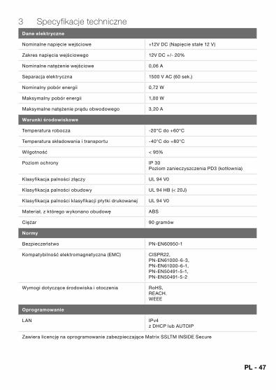
3 Specyfikacje techniczneDane elektryczne
Nominalne napięcie wejściowe +12V DC (Napięcie stałe 12 V)
Zakres napięcia wejściowego 12V DC +/- 20%
Nominalne natężenie wejściowe 0,06 A
Separacja elektryczna 1500 V AC (60 sek.)
Nominalny pobór energii 0,72 W
Maksymalny pobór energii 1,00 W
Maksymalne natężenie prądu obwodowego 3,20 A
Warunki środowiskowe
Temperatura robocza -20°C do +60°C
Temperatura składowania i transportu -40°C do +80°C
Wilgotność < 95%
Poziom ochrony IP 30 Poziom zanieczyszczenia PD3 (kotłownia)
Klasyfikacja palności złączy UL 94 V0
Klasyfikacja palności obudowy UL 94 HB (< 20J)
Klasyfikacja palności klasyfikacji płytki drukowanej UL 94 V0
Materiał, z którego wykonano obudowę ABS
Ciężar 90 gramów
Normy
Bezpieczeństwo PN-EN60950-1
Kompatybilność elektromagnetyczna (EMC) CISPR22, PN-EN61000-6-3, PN-EN61000-6-1, PN-EN50491-5-1, PN-EN50491-5-2
Wymogi dotyczące środowiska i otoczenia RoHS, REACH.WEEE
Oprogramowanie
LAN IPv4 z DHCP lub AUTOIP
Zawiera licencję na oprogramowanie zabezpieczające Matrix SSLTM INSIDE Secure
48 - PL
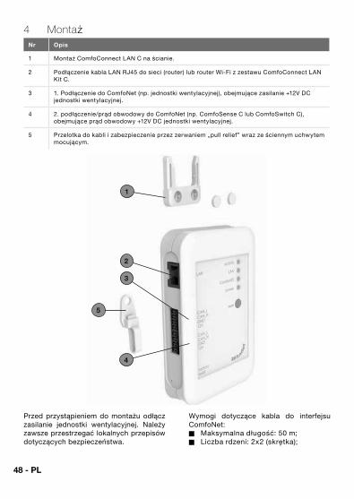
4 MontażNr Opis
1 Montaż ComfoConnect LAN C na ścianie.
2 Podłączenie kabla LAN RJ45 do sieci (router) lub router Wi-Fi z zestawu ComfoConnect LAN Kit C.
3 1. Podłączenie do ComfoNet (np. jednostki wentylacyjnej), obejmujące zasilanie +12V DC jednostki wentylacyjnej.
4 2. podłączenie/prąd obwodowy do ComfoNet (np. ComfoSense C lub ComfoSwitch C), obejmujące prąd obwodowy +12V DC jednostki wentylacyjnej.
5 Przelotka do kabli i zabezpieczenie przez zerwaniem „pull relief” wraz ze ściennym uchwytem mocującym.
1
2
5
3
4
Przed przystąpieniem do montażu odłącz zasilanie jednostki wentylacyjnej. Należy zawsze przestrzegać lokalnych przepisów dotyczących bezpieczeństwa.
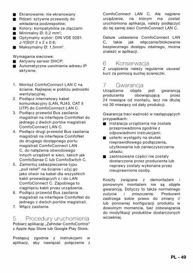
Wymogi dotyczące kabla do interfejsu ComfoNet:� Maksymalna długość: 50 m;� Liczba rdzeni: 2x2 (skrętka);
PL - 49
� Ekranowanie: nie ekranowany� Rdzeń: sztywne przewody do
wkładania podzespołów;� Kolory: kompatybilne ze złączami� Minimalny Ø: 0,2 mm2;� Optymalny wybór: DIN VDE 0281:
J-Y(St)Y 2 x 2 x 0.6;� Maksymalny Ø: 1,5mm2.
Wymagania sieciowe:� Aktywny serwer DHCP;� Automatyczne uwolnienie adresu IP
aktywne.
1. Montaż ComfoConnect LAN C na ścianie. Najlepiej w pobliżu jednostki wentylacyjnej.
2. Podłącz internetowy kabel komunikacyjny (LAN, RJ45, CAT 5 UTP) do ComfoConnect LAN C.
3. Podłącz przewód Bus zasilania magistrali na interfejsie ComfoNet do jednego z dwóch portów magistrali ComfoConnect LAN C.
4. Podłącz drugi przewód Bus zasilania magistrali na interfejsie ComfoNet do drugiego dostępnego portu magistrali ComfoConnect LAN C, do natężenia obwodowego innych urządzeń w sieci, takich jak ComfoSense C lub ComfoSwitch C.
5. Zamontuj zabezpieczenie typu „pull relief” na ścianie i użyj go jako otwór na kabel dla wszystkich kabli prowadzących z i do LAN ComfoConnect C. Zapobiega to ciągnięciu kabli przez urządzenia.
6. Podłącz przewód Bus zasilania magistrali na interfejsie ComfoNet do jednego z dwóch portów magistrali.
7. Włącz zasilanie.
5 Procedury uruchomieniaPobierz aplikację „Zehnder ComfoControl” z Apple App Store lub Google Play Store.
Postępuj zgodnie z instrukcjami w aplikacji, aby nawiązać połączenie z
ComfoConnect LAN C. Ale najpierw urządzenie, na którym ma zostać uruchomiona aplikacja, należy podłączyć do tej samej sieci ComfoConnect LAN C.
Dalsze ustawienia ComfoConnect LAN C, takie jak włączanie/blokowanie bezpiecznego dostępu zdalnego, można znaleźć w aplikacji.
6 KonserwacjaZ urządzenia należy regularnie usuwać kurz za pomocą suchej ściereczki.
7 GwarancjaUrządzenie objęte jest gwarancją producenta obowiązującą przez 24 miesiące od montażu, lecz nie dłużej niż 30 miesięcy od daty produkcji.
Gwarancja traci ważność w następujących przypadkach:� Instalacja urządzenia nie została
przeprowadzona zgodnie z odpowiednimi instrukcjami;
� usterki wystąpiły na skutek nieprawidłowego podłączenia, użytkowania lub zanieczyszczenia układu;
� zastosowane części nie zostały dostarczone przez producenta lub naprawy zostały wykonane przez nieuprawnione osoby.
Koszty związane z demontażem i ponownym montażem nie są objęte gwarancją. Dotyczy to także normalnego zużycia i zniszczenia. Producent zastrzega sobie prawo do zmiany i/lub ponownej konfiguracji produktu w dowolnym momencie, bez zobowiązania do modyfikacji produktów dostarczonych wcześniej.

50

51
ZG
NL_
Man
ual D
2016
0301
, V05
16, N
L_E
N_D
E_F
R_I
T_P
L, S
ubje
ct to
cha
nge
Nederland (The Netherlands)Zehnder Group Nederland B.V.Lingenstraat 2, 8028 PM ZwollePostbus 621, 8000 AP ZwolleTel.: 0900 555 19 37 (€ 0.10 a minute, NL only)Fax: (038) 422 56 94Internet: www.zehnder.nlE-mail: [email protected]
België (Belgium)Zehnder Group Belgium NV/SATel.: +32 (0)15-28 05 10Internet: www.zehnder.beE-mail: [email protected] (Germany)
Deutschland (Germany)Zehnder Group Deutschland GmbHTel.: +49 (0) 7821 / 586-0Internet: www.zehnder-systems.deE-mail: [email protected]
France (France)Zehnder Group France -Activité VentilationTel.: +33 (0)1 69 36 16 46Internet: www.zehnder.frE-mail: [email protected]
Italia (Italy)Zehnder Group Italia S.r.l.Tel.: +39 059 978 62 00Internet: www.zehnder.itE-mail: [email protected]
Österreich (Austria)Wernig kunststoff- und lüftungstechnikTel.: 04227.22130Internet: www.wernig.atE-mail: [email protected]
Polska (Poland)Zehnder Polska Sp. z o.o.Tel.: +48 (0) 71 367 64 24Internet: www.zehnder.plE-mail: [email protected]
Roha Group Sp. z o.o.VentermoTel: +48 (0) 71 352 78 28Internet: www.ventermo.plE-mail: [email protected]
Schweiz (Switzerland)Zehnder Group Schweiz AGTel.: +41 (0)43 / 833 20 20Internet: www.zehnder-systems.chE-mail: [email protected]
United KingdomZehnder Group UK LtdTel.: +44 (0) 01276 605800Internet: www.zehnderpassivehouse.co.ukE-mail: [email protected]