
HDMI/YPbPr MPEG2/4 ENCODER/MODULATOR - …...PRGM HDMI/YPbPr MPEG2/4 ENCODER/MODULATOR - QAM/COFDM...
12
Ref. 566001 Art. Nr. UHDMI-QAC-S www.televes.com HDMI/YPbPr MPEG2/4 ENCODER/MODULATOR - QAM/COFDM EN QUICK INSTALLATION GUIDE GUÍA DE INSTALACIÓN RÁPIDA HDMI/YPbPr MPEG2/4 ENCODER/MODULATOR - QAM/COFDM ES
Transcript of HDMI/YPbPr MPEG2/4 ENCODER/MODULATOR - …...PRGM HDMI/YPbPr MPEG2/4 ENCODER/MODULATOR - QAM/COFDM...

Ref. 566001Art. Nr. UHDMI-QAC-S
w w w . t e l e v e s . c o m
HDMI/YPbPr MPEG2/4 ENCODER/MODULATOR - QAM/COFDMEN QUICK INSTALLATION GUIDE
GUÍA DE INSTALACIÓN RÁPIDAHDMI/YPbPr MPEG2/4 ENCODER/MODULATOR - QAM/COFDMES

Condiciones generales de instalación 1. Lea las instrucciones.2. Conserve estas instrucciones.3. Preste atención a todas las advertencias.4. Siga todas las instrucciones.5. No utilice este aparato cerca del agua.6. Limpie la unidad sólo con un paño seco. 7. No bloquee las aberturas de ventilación. Realizar
la instalación de acuerdo con las instrucciones del fabricante.
8. No la instale cerca de fuentes de calor tales como radiadores, registros de calor, estufas u otros aparatos (incluyendo amplificadores) que produzcan calor.
9. No anule la característica de seguridad del enchufe polarizado o con conexión a tierra de la fuente de alimentación. Un enchufe polarizado tiene dos patillas planas, una más ancha que la otra. Un enchufe con toma de tierra tiene dos patillas planas y una tercera de conexión a tierra. La patilla ancha o la tercera patilla, están pensadas para su seguridad. Si el enchufe suministrado no encaja en su toma, consulte con un electricista para que reemplace la toma corriente obsoleta.
10. No pise ni pellizque el cable de red de la fuente de alimentación; tenga especial cuidado con las clavijas, tomas de corriente y en el punto del cual salen de la fuente.
11. Utilice solamente los aditamentos/accesorios especificados por el fabricante.
12. Use únicamente la carretilla, plataforma, trípode, soporte o tableros especificados por el fabricante, o vendidos con el aparato. Cuando se usa una
carretilla, tenga cuidado al mover el conjunto carretilla/aparatos para evitar lesiones en caso de vuelco.
13. Desenchufe este aparato durante las tormentas eléctricas o cuando no lo utilice durante largos períodos de tiempo.
14. Solicite todas las reparaciones a personal de servicio cualificado. Solicite una reparación cuando el aparato se haya dañado de cualquiera forma, como cuando el cable de red o el enchufe están dañados, se ha derramado líquido o han caído objetos dentro del aparato, el aparato ha sido expuesto a la lluvia o humedad, no funciona normalmente, o haya sufrido una caída.
Atención Para reducir el riesgo de fuego o choque eléctrico, no
exponer el la fuente de alimentación a la lluvia o a la humedad.
El aparato no debe ser expuesto a caídas o salpicaduras de agua. No situar objetos o recipientes llenos de líquidos, como vasos, sobre o cerca del aparato.
Cómo utilizar el equipo de forma segura La tensión de red de la fuente de alimentación de este
producto ha de ser: 99 -254V~ 50/60Hz. En el caso de que cualquier líquido u objeto caigan
dentro del aparato, debe de ponerse en contacto con el servicio técnico.
Para desenchufar la fuente de alimentación de la red, tire siempre de la clavija, nunca del cable.
No enchufe la fuente de alimentación a la red eléctrica hasta que todas las demás conexiones hayan sido
realizadas. La toma de red eléctrica debe estar cerca del equipo y
ser fácilmente accesible. No abrir la fuente de alimentación sin desconectarla
de la red.
Instalación segura La temperatura ambiente no debe superar los 45°C. No situar el equipo cerca de fuentes de calor o en
ambientes de humedad elevada. No situar el equipo donde pueda estar sometido a
fuertes vibraciones o sacudidas. Deje un espacio libre alrededor del aparato para
proporcionar una ventilación adecuada. No situar sobre el aparato fuentes de llama desnuda,
tales como velas encendidas.
Simbología
Equipo diseñado para uso en interiores.
La fuente de alimentación (incluída) cumple los requerimientos de seguridad para equipos de clase II.
Precaución, peligro de descargar eléctrica.
El equipo cumple los requerimientos del marcado CE.
Important safety instruccions1. Read these instructions.2. Keep these instructions.3. Heed all warnings.4. Follow all instructions.5. Do not use this apparatus near water.6. Clean only with a dry cloth.7. Do not block any ventilation openings. Install in
accordance with the manufacturer’s instructions.8. Do not install near any heat sources such as radiators,
heat registers, stoves, or other apparatus (including amplifiers) that produce heat.
9. Do not defeat the safety purpose of the polarized or grounding-type plug. A polarized plug has two blades with one wider than the other. A grounding type plug has two blades and a third grounding prong. The wide blade or the third prong are provided for your safety. When the provided plug does not fit into your outlet, consult an electrician for replacement of the obsolete outlet.
10. Protect ( in the power supply) the power cord from being walked on or pinched particularly at plugs, convenience receptacles, and the point where they exit the apparatus.
11. Only use attachments/accessories specified by the manufacturer.
12. Use only with the cart, stand, tripod, bracket, or table specified by the manufacturer, or sold with the
apparatus. When a cart is used, use caution when moving the cart/apparatus combination to avoid injury from tip-over.
13. Unplug this apparatus during lightning storms or when unused for long periods of time.
14. Refer all servicing to qualified service personnel. Servicing is required when the apparatus has been damaged in any way, such as power-supply cord or plug is damaged, liquid has been spilled or objects have fallen into the apparatus, the apparatus has been exposed to rain or moisture, does not operate normally, or has been dropped.
Warning Reduce the risk of fire or electric shock, do not expose
this apparatus to rain or moisture. Apparatus shall not be exposed to dripping or
splashing and no objects filled with liquids, such as glasses, shall be placed on the apparatus.
Safe operation Power requirements for the power supply in this
product are 99 - 254V~ 50/60 Hz. Should any liquid or object fall into the equipment,
please refer to qualified personnel for service. To disconnect the power supply from the mains pull
the plug never the cable. It is strongly recommended not to connect the power
supply to the mains until all connections have been
done. The socket outlet shall be installed near the equipment
and shall be easily accessible. Do not open the power suply without disconnecting
it from the mains.
Safe installation Ambient temperature should not be higher than ºF:
45ºC (113ºF). Do not place the equipment near heat sources or in a
highly humid environment. Do not place the equipment in a place where it can
suffer vibrations or shocks. Please allow air circulation around the equipment. Do not place naked flames, such as lighted candles on
or near the product.
Simbology
Equipment designed for indoor use.
This symbol indicates that the power supply (included) complies with the safety requirements for class II equipment.
Caution, risk of electrical shock.
The equipment complies with the CE mark requirements.
Important safety instructions
Importantes instrucciones de seguridad
EN
ES
DECLARACIÓN DE CONFORMIDAD DECLARATION OF CONFORMITY DECLARAÇÃO DE CONFORMIDADE DECLARATION DE CONFORMITE DICHIARAZIONE DI CONFORMITÀ DEKLARACJA ZGODNOŚCI KONFORMITÄTSERKLÄRUNG ΠΙΣΤΟΠΟΙΗΤΙΚΟ ΣΥΜΜΟΡΦΩΣΗΣ FÖRSÄKRAN OM ÖVERENSSTÄMMELSE ДЕКЛАРАЦИЯ СООТВЕТСТВИЯ www.doc.televes.com
PRGM
HDM
I/YPb
Pr M
PEG2
/4 E
NCOD
ER/M
ODUL
ATOR
- QA
M/C
OFDM
UHDM
I-QA
C-S
PWR
ETHERNET
TEMP
CH1
OUTP
UT
LOOP
10/100
1000
Link
MADE IN SPAIN
Input 1Y
Pb
Pr
CVBS
R
L
HD
MI
1
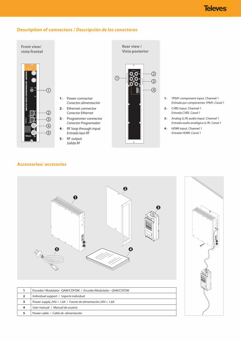
Rear view / Vista posterior
Description of connectors / Descripción de los conectores
1.- YPbPr component input. Channel 1 Entrada por componentes YPbPr. Canal 1
2.- CVBS input. Channel 1 Entrada CVBS. Canal 1
3.- Analog (L/R) audio input. Channel 1 Entrada audio analógica (L/R). Canal 1
4.- HDMI input. Channel 1 Entrada HDMI. Canal 1
1.- Power connector Conector alimentación
2.- Ethernet connector Conector Ethernet
3.- Programmer connector Conector Programador
4.- RF loop through input Entrada lazo RF
5.- RF output Salida RF
Front view/vista frontal
Accessories/ accesorios
1 Encoder/ Modulator -QAM/COFDM / Encoder/Modulador - QAM/COFDM
2 Individual support / Soporte individual
3 Power supply 24V 1,6A / Fuente de alimentación 24V 1,6A
4 User manual / Manual de usuario
5 Power cable / Cable de alimentación
1
2
3
5 4
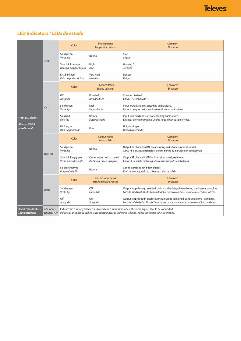
LED indicators / LEDs de estado
Front LED alarms
Alarmas (LEDs)panel frontal
TEMP
ColorInternal temp
Temperatura internaCommentSituación
Solid greenVerde, fijo
NormalSafeSeguro
Slow blink orangeNaranja, parpadeo lento
HighAlta
Warning *Atención
Fast blink redRojo, parpadeo rápido
Very HighMuy Alta
DangerPeligro
CH1
ColorChannel statusEstado del canal
CommentSituación
OffApagado
DisabledDeshabilitado
Channel disabled.Canales deshabilitados.
Solid greenVerde, fijo
LockEnganchado
Input locked and unit encoding audio/video.Entradas enganchadas y unidad codificando audio/video.
Solid redRojo, fijo
UnlockDesengachado
Input unlocked and unit not encoding audio/video.Entradas desenganchadas y unidad no codificando audio/video.
Blinking redRojo, parpadeando
BootUnit starting up.Unidad reiniciando.
OUTPUT
ColorOutput mode
Modo salidaCommentSituación
Solid greenVerde, fijo
NormalOutput RF channel is ON, broadcasting audio/video (normal mode).Canal RF de salida encendido, transmitiendo audio/video (modo normal).
Slow blinking greenVerde, parpadeo lento
Carrier wave, null, or mutedPortadora, nulo o apagado
Output RF channel is OFF or in an alternate signal mode. Canal RF de salida está apagado o en un modo de señal alterno.
Solid orange/redNaranja/rojo, fijo
NormalConfig bitrate doesn´t fit in outputEl bit rate configurado no cabe en la señal de salida
LOOP
ColorOutput loop status
Estado del lazo de salidaCommentSituación
Solid greenVerde, fijo
ONEncendido
Output loop-through enabled. Units may be daisy-chained using the internal combiner.Lazo de salida habilitado. Las unidades se pueden combinar usando el mezclador interno.
OffApagado
OFFApagado
Output loop-through disabled. Units must be combined using an external combiner.Lazo de salida deshabilitado. Debe usarse un mezclador externo para combinar unidades.
Back LED indicatorsLEDs posteriores
A/V inputsEntradas A/V
Indicate the currently selected audio and video inputs and where the input signals should be connected.Indican las entradas de audio y video seleccionadas actualmente y dónde se debe conectar la señal de entrada.
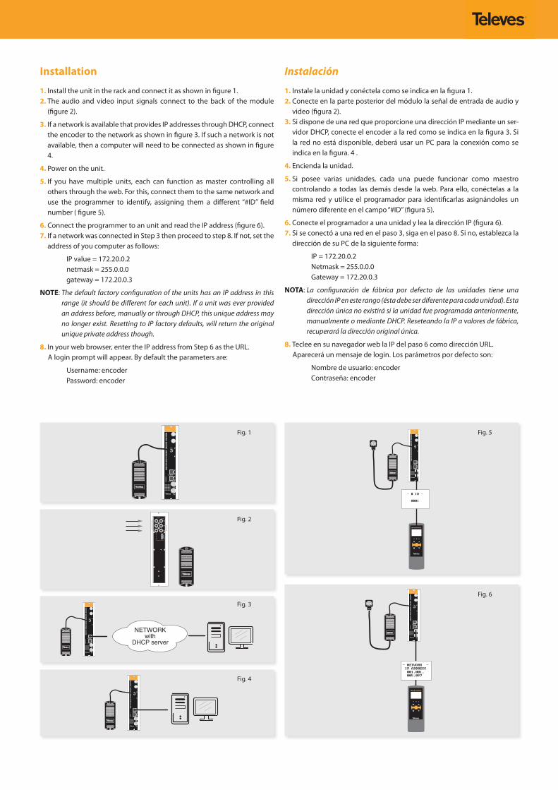
Installation
1. Install the unit in the rack and connect it as shown in figure 1.2. The audio and video input signals connect to the back of the module
(figure 2).
3. If a network is available that provides IP addresses through DHCP, connect the encoder to the network as shown in figure 3. If such a network is not available, then a computer will need to be connected as shown in figure 4.
4. Power on the unit.
5. If you have multiple units, each can function as master controlling all others through the web. For this, connect them to the same network and use the programmer to identify, assigning them a different “#ID” field number ( figure 5).
6. Connect the programmer to an unit and read the IP address (figure 6).7. If a network was connected in Step 3 then proceed to step 8. If not, set the
address of you computer as follows:
IP value = 172.20.0.2netmask = 255.0.0.0gateway = 172.20.0.3
NOTE: The default factory configuration of the units has an IP address in this range (it should be different for each unit). If a unit was ever provided an address before, manually or through DHCP, this unique address may no longer exist. Resetting to IP factory defaults, will return the original unique private address though.
8. In your web browser, enter the IP address from Step 6 as the URL. A login prompt will appear. By default the parameters are:
Username: encoderPassword: encoder
Instalación
1. Instale la unidad y conéctela como se indica en la figura 1.2. Conecte en la parte posterior del módulo la señal de entrada de audio y
video (figura 2).3. Si dispone de una red que proporcione una dirección IP mediante un ser-
vidor DHCP, conecte el encoder a la red como se indica en la figura 3. Si la red no está disponible, deberá usar un PC para la conexión como se indica en la figura. 4 .
4. Encienda la unidad.
5. Si posee varias unidades, cada una puede funcionar como maestro controlando a todas las demás desde la web. Para ello, conéctelas a la misma red y utilice el programador para identificarlas asignándoles un número diferente en el campo “#ID” (figura 5).
6. Conecte el programador a una unidad y lea la dirección IP (figura 6).7. Si se conectó a una red en el paso 3, siga en el paso 8. Si no, establezca la
dirección de su PC de la siguiente forma:
IP = 172.20.0.2Netmask = 255.0.0.0Gateway = 172.20.0.3
NOTA: La configuración de fábrica por defecto de las unidades tiene una dirección IP en este rango (ésta debe ser diferente para cada unidad). Esta dirección única no existirá si la unidad fue programada anteriormente, manualmente o mediante DHCP. Reseteando la IP a valores de fábrica, recuperará la dirección original única.
8. Teclee en su navegador web la IP del paso 6 como dirección URL. Aparecerá un mensaje de login. Los parámetros por defecto son:
Nombre de usuario: encoderContraseña: encoder
PRGM
HDM
I/YPb
Pr M
PEG2
/4 E
NCOD
ER/M
ODUL
ATOR
- QA
M/C
OFDM
UHDM
I-QA
C-T
PWR
ETHERNET
TEMP
CH1
OUTP
UT
LOOP
10/100
1000
Link
MADE IN SPAIN
PRGM
HDM
I/YPb
Pr M
PEG2
/4 E
NCOD
ER/M
ODUL
ATOR
- QA
M/C
OFDM
UHDM
I-QA
C-T
PWR
ETHERNET
TEMP
CH1
OUTP
UT
LOOP
10/100
1000
Link
MADE IN SPAIN
Input 1Y
Pb
Pr
CVBS
R
L
HD
MI
1
PRGM
HDM
I/YPb
Pr M
PEG2
/4 E
NCOD
ER/M
ODUL
ATOR
- QA
M/C
OFDM
UHDM
I-QA
C-T
PWR
ETHERNET
TEMP
CH1
OUTP
UT
LOOP
10/100
1000
Link
MADE IN SPAIN
PRGM
HDM
I/YPb
Pr M
PEG2
/4 E
NCOD
ER/M
ODUL
ATOR
- QA
M/C
OFDM
UHDM
I-QA
C-T
PWR
ETHERNET
TEMP
CH1
OUTP
UT
LOOP
10/100
1000
Link
MADE IN SPAIN
PRGM
HDM
I/YPb
Pr M
PEG2
/4 E
NCOD
ER/M
ODUL
ATOR
- QA
M/C
OFDM
UHDM
I-QA
C-T
PWR
ETHERNET
TEMP
CH1
OUT
PUT
LOOP
10/100
1000
Link
MADE IN SPAIN
Fig. 1
Fig. 2
Fig. 3
Fig. 4
Fig. 5
Fig. 6
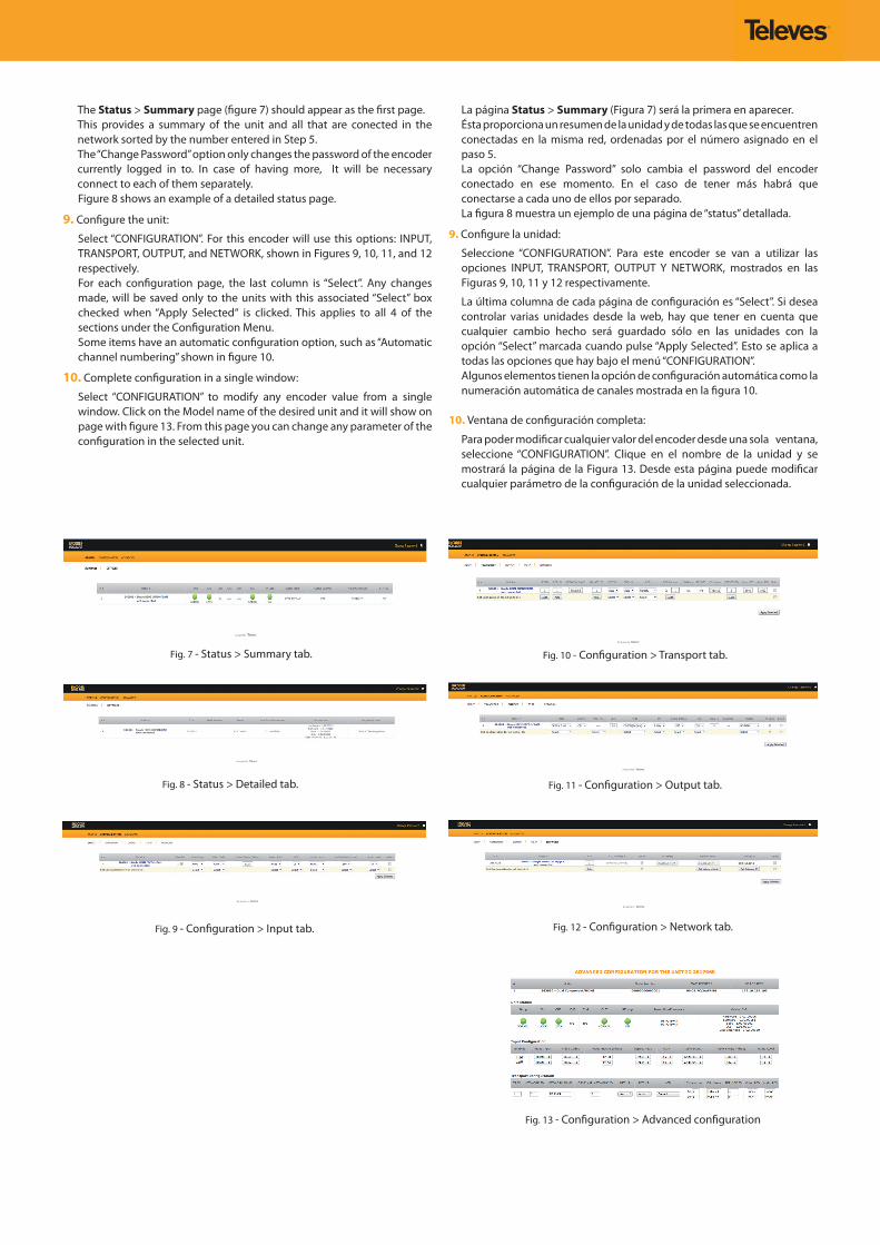
Fig. 7 - Status > Summary tab.
Fig. 8 - Status > Detailed tab.
Fig. 9 - Configuration > Input tab.
Fig. 10 - Configuration > Transport tab.
Fig. 11 - Configuration > Output tab.
Fig. 12 - Configuration > Network tab.
Fig. 13 - Configuration > Advanced configuration
The Status > Summary page (figure 7) should appear as the first page. This provides a summary of the unit and all that are conected in the
network sorted by the number entered in Step 5. The “Change Password” option only changes the password of the encoder
currently logged in to. In case of having more, It will be necessary connect to each of them separately.
Figure 8 shows an example of a detailed status page.
9. Configure the unit:
Select “CONFIGURATION”. For this encoder will use this options: INPUT, TRANSPORT, OUTPUT, and NETWORK, shown in Figures 9, 10, 11, and 12 respectively.
For each configuration page, the last column is “Select”. Any changes made, will be saved only to the units with this associated “Select” box checked when “Apply Selected“ is clicked. This applies to all 4 of the sections under the Configuration Menu.
Some items have an automatic configuration option, such as “Automatic channel numbering” shown in figure 10.
10. Complete configuration in a single window:
Select “CONFIGURATION” to modify any encoder value from a single window. Click on the Model name of the desired unit and it will show on page with figure 13. From this page you can change any parameter of the configuration in the selected unit.
La página Status > Summary (Figura 7) será la primera en aparecer. Ésta proporciona un resumen de la unidad y de todas las que se encuentren
conectadas en la misma red, ordenadas por el número asignado en el paso 5.
La opción “Change Password” solo cambia el password del encoder conectado en ese momento. En el caso de tener más habrá que conectarse a cada uno de ellos por separado.
La figura 8 muestra un ejemplo de una página de “status” detallada.
9. Configure la unidad:
Seleccione “CONFIGURATION”. Para este encoder se van a utilizar las opciones INPUT, TRANSPORT, OUTPUT Y NETWORK, mostrados en las Figuras 9, 10, 11 y 12 respectivamente.
La última columna de cada página de configuración es “Select”. Si desea controlar varias unidades desde la web, hay que tener en cuenta que cualquier cambio hecho será guardado sólo en las unidades con la opción “Select” marcada cuando pulse “Apply Selected”. Esto se aplica a todas las opciones que hay bajo el menú “CONFIGURATION”.
Algunos elementos tienen la opción de configuración automática como la numeración automática de canales mostrada en la figura 10.
10. Ventana de configuración completa:
Para poder modificar cualquier valor del encoder desde una sola ventana, seleccione “CONFIGURATION”. Clique en el nombre de la unidad y se mostrará la página de la Figura 13. Desde esta página puede modificar cualquier parámetro de la configuración de la unidad seleccionada.
- OUTPUT -
FREQ STEP
166 KhZ
- TEMP -
NOW: 116 C
MAX: 187 C
- OUTPUT -
BANDWIDTH
8 Mhz
QA
M M
OD
E O
NLY
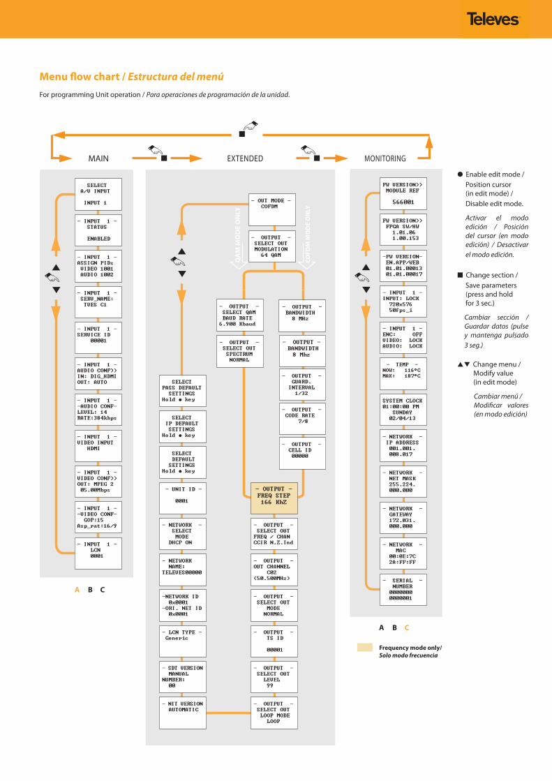
Frequency mode only/Solo modo frecuencia
Enable edit mode / Position cursor (in edit mode) / Disable edit mode.
Activar el modo edición / Posición del cursor (en modo edición) / Desactivar el modo edición.
Change section / Save parameters
(press and hold for 3 sec.)
Cambiar sección / Guardar datos (pulse y mantenga pulsado 3 seg.)
Change menu / Modify value
(in edit mode)
Cambiar menú / Modificar valores (en modo edición)
Menu flow chart / Estructura del menúFor programming Unit operation / Para operaciones de programación de la unidad.
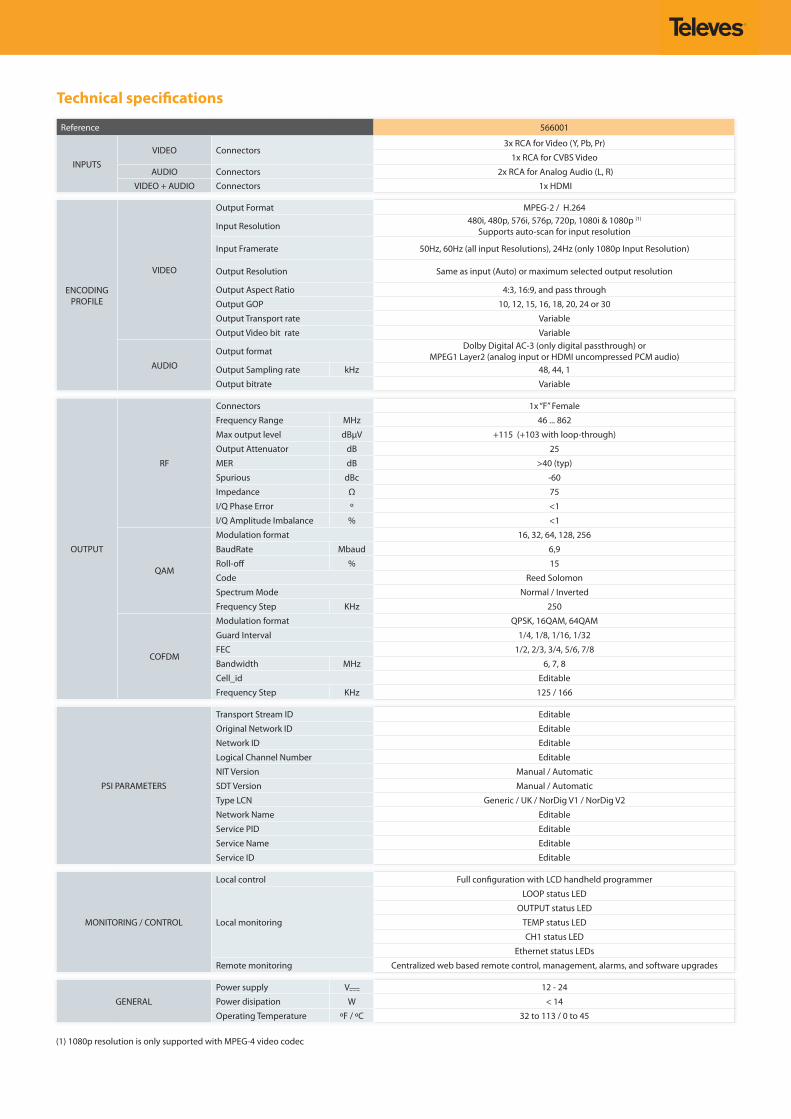
Technical specifications
Reference 566001
INPUTS
VIDEO Connectors3x RCA for Video (Y, Pb, Pr)
1x RCA for CVBS Video
AUDIO Connectors 2x RCA for Analog Audio (L, R)
VIDEO + AUDIO Connectors 1x HDMI
ENCODING PROFILE
VIDEO
Output Format MPEG-2 / H.264
Input Resolution 480i, 480p, 576i, 576p, 720p, 1080i & 1080p (1)
Supports auto-scan for input resolution
Input Framerate 50Hz, 60Hz (all input Resolutions), 24Hz (only 1080p Input Resolution)
Output Resolution Same as input (Auto) or maximum selected output resolution
Output Aspect Ratio 4:3, 16:9, and pass through
Output GOP 10, 12, 15, 16, 18, 20, 24 or 30
Output Transport rate Variable
Output Video bit rate Variable
AUDIO
Output format Dolby Digital AC-3 (only digital passthrough) or MPEG1 Layer2 (analog input or HDMI uncompressed PCM audio)
Output Sampling rate kHz 48, 44, 1
Output bitrate Variable
OUTPUT
RF
Connectors 1x “F” Female
Frequency Range MHz 46 ... 862
Max output level dBµV +115 (+103 with loop-through)
Output Attenuator dB 25
MER dB >40 (typ)
Spurious dBc -60
Impedance Ω 75
I/Q Phase Error º <1
I/Q Amplitude Imbalance % <1
QAM
Modulation format 16, 32, 64, 128, 256
BaudRate Mbaud 6,9
Roll-off % 15
Code Reed Solomon
Spectrum Mode Normal / Inverted
Frequency Step KHz 250
COFDM
Modulation format QPSK, 16QAM, 64QAM
Guard Interval 1/4, 1/8, 1/16, 1/32
FEC 1/2, 2/3, 3/4, 5/6, 7/8
Bandwidth MHz 6, 7, 8
Cell_id Editable
Frequency Step KHz 125 / 166
PSI PARAMETERS
Transport Stream ID Editable
Original Network ID Editable
Network ID Editable
Logical Channel Number Editable
NIT Version Manual / Automatic
SDT Version Manual / Automatic
Type LCN Generic / UK / NorDig V1 / NorDig V2
Network Name Editable
Service PID Editable
Service Name Editable
Service ID Editable
MONITORING / CONTROL
Local control Full configuration with LCD handheld programmer
Local monitoring
LOOP status LED
OUTPUT status LED
TEMP status LED
CH1 status LED
Ethernet status LEDs
Remote monitoring Centralized web based remote control, management, alarms, and software upgrades
GENERAL
Power supply V 12 - 24
Power disipation W < 14
Operating Temperature ºF / ºC 32 to 113 / 0 to 45
(1) 1080p resolution is only supported with MPEG-4 video codec
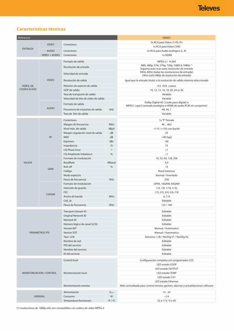
Características técnicas
Referencia 566001
ENTRADA
VIDEO Conectores3x RCA para Video (Y, Pb, Pr)
1x RCA para Video CVBS
AUDIO Conectores 2x RCA para Audio analógico (L, R)
VIDEO + AUDIO Conectores 1x HDMI
PERFIL DE CODIFICACIÓN
VIDEO
Formato de salida MPEG-2 / H.264
Resolución de entrada 480i, 480p, 576i, 576p, 720p, 1080i & 1080p (1)
Soporta auto-scan para resolución de entrada
Velocidad de entrada 50Hz, 60Hz (todas las resoluciones de entrada), 24Hz (solo1080p de resolución de entrada)
Resolución de salida Igual que la entrada (Auto) o la resolución de salida máxima seleccionada
Relación de aspecto de salida 4:3, 16:9, y paso
GOP de salida 10, 12, 15, 16, 18, 20, 24 or 30
Tasa de transporte de salida Variable
Velocidad de bits de video de salida Variable
AUDIO
Formato de salida Dolby Digital AC-3 (solo paso digital) o MPEG1 Layer2 (entrada analógica o HDMI de audio PCM sin comprimir)
Frecuencia de muestreo de salida kHz 48, 44, 1
Tasa de bits de salida Variable
SALIDA
RF
Conectores 1x “F” Female
Margen de frecuencia MHz 46 ... 862
Nivel máx. de salida dBµV +115 (+103 con bucle)
Margen regulación nivel de salida dB 25
MER dB >40 (typ)
Espúreos dBc -60
Impedancia Ω 75
I/Q Phase Error º <1
I/Q Amplitude Imbalance % <1
QAM
Formato de modulación 16, 32, 64, 128, 256
BaudRate Mbaud 6,9
Roll-off % 15
Código Reed Solomon
Modo espectro Normal / Invertedo
Pasos de frecuencia KHz 250
COFDM
Formato de modulación QPSK, 16QAM, 64QAM
Intervalo de guarda 1/4, 1/8, 1/16, 1/32
FEC 1/2, 2/3, 3/4, 5/6, 7/8
Ancho de banda MHz 6, 7, 8
Cell_id Editable
Pasos de frecuencia KHz 125 / 166
PARAMETROS PSI
Transport Stream ID Editable
Original Network ID Editable
Network ID Editable
Número lógico de canal (LCN) Editable
Version NIT Manual / Automatico
Version SDT Manual / Automatico
Tipo LCN Generico / UK / NorDig V1 / NorDig V2
Nombre de red Editable
PID del servicio Editable
Nombre del servicio Editable
ID del servicio Editable
MONITORIZACION / CONTROL
Control local Configuración completa con programador LCD
Monitorización local
LED estado LOOP
LED estado OUTPUT
LED estado TEMP
LED estado CH1
LED estado Ethernet
Monitorización remota Web centralizada para control remoto, gestión, alarmas y actualizaciones software
GENERAL
Alimentación V 12 - 24
Consumo W <14
Temperatura funcionam. ºF / ºC 32 a 113 / 0 a 45
(1) resoluciones de 1080p sólo son compatibles con codecs de vídeo MPEG-4


www.televes.com