GRAPE: A CASE Tool for Digital Signal Parallel Processing
12
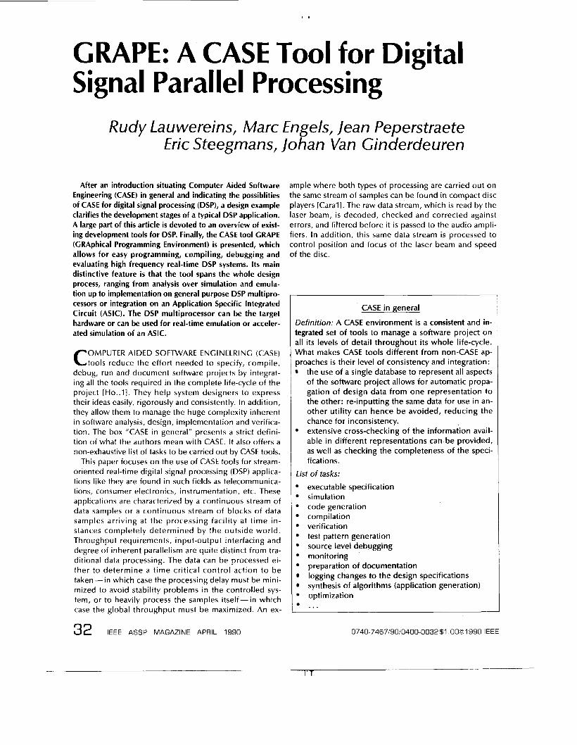
GRAPE: A CASE Tool for Digital Signal Parallel Processing Rudy Lauwereins, Marc Engels, lean Peperstraete Eric Steegmans, lohan Van Ginderdeuren After an introduction situating Computer Aided Software Engineering (CASE) in general and indicating the possiblities of CASE for digital signal processing (DSP), a design example clarifies the development stages of a typical DSP application. A large part of this article is devoted to an overview of exist- ing development tools for DSP. Finally, the CASE tool GRAPE (GRAphical Programming Environment) is presented, which allows for easy programming, compiling, debugging and evaluating high frequency real-time DSP systems. Its main distinctive feature is that the tool spans the whole design process, ranging from analysis over simulation and emula- tion up to implementation on general purpose DSP multipro- cessors or integration on an Application Specific Integrated Circuit (ASIC). The DSP multiprocessor can be the target hardware or can be used for real-time emulation or acceler- ated simulation of an ASIC. OMPUTER AIDED SOFTWARE ENGINEERING (CASE) C tools reduce the effort needed to specify, compile, debug, run and document software projects by integrat- ing all the tools required in the complete life-cycle of the project [Ho..~]. They help system designers to express their ideas easily, rigorously and consistently. In addition, they allow them to manage the huge complexity inherent in software analysis, design, implementation and verifica- tion. The box "CASE in general" presents a strict defini- tion of what the authors mean with CASE. It also offers a non-exhaustive list of tasks to be carried out by CASE tools. This paper focuses on the use of CASE tools for stream- oriented real-time digital signal processing (DSP) applica- tions like they are found in such fields as telecommunica- tions, consumer electronics, instrumentation, etc. These applications are characterized by a continuous stream of data samples or a continuous stream of blocks of data samples arriving at the processing facility at time in- stances completely determined by the outside world. Throughput requirements, input-output interfacing and degree of inherent parallelism are quite distinct from tra- ditional data processing. The data can be processed ei- ther to determine a time critical control action to be taken-in which case the processing delay must be mini- mized to avoid stability problems in the controlled sys- tem, or to heavily process the samples itself- in which case the global throughput must be maximized. An ex- 32 iEEE ASSP MAGAZINE APRIL 1990 ample where both types of processing are carried out on the same stream of samples can be found in compact disc players [Carall. The raw data stream, which is read by the laser beam, is decoded, checked and corrected against errors, and filtered before it is passed to the audio ampli- fiers. In addition, this same data stream is processed to control position and focus of the laser beam and speed of the disc. CASE in general Definition: A CASE environment is a consistent and in- tegrated set of tools to manage a software project on all its levels of detail throughout its whole life-cycle. What makes CASE tools different from non-CASE ap- proaches is their level of consistency and integration: the use of a single database to represent all aspects of the software project allows for automatic propa- gation of design data from one representation to the other: re-inputting the same data for use in an- other utility can hence be avoided, reducing the chance for inconsistency. extensive cross-checking of the information avail- able in different representations can be provided, as well as checking the completeness of the speci- fications. List of tasks: executable specification simulation code generation compilation verification test pattern generation source level debugging monitoring preparation of documentation logging changes to the design specifications synthesis of algorithms (application generation) optimization ... 0740-7467/90/0400-0032$1 .0001990 IEEE - 1 ' '1
Transcript of GRAPE: A CASE Tool for Digital Signal Parallel Processing
GRAPE: A CASE Tool for Digital Signal Parallel Processing
Rudy Lauwereins, Marc Engels, lean Peperstraete Eric Steegmans, lohan Van Ginderdeuren
After an introduction situating Computer Aided Software Engineering (CASE) in general and indicating the possiblities of CASE for digital signal processing (DSP), a design example clarifies the development stages of a typical DSP application. A large part of this article i s devoted to an overview of exist- ing development tools for DSP. Finally, the CASE tool GRAPE (GRAphical Programming Environment) is presented, which allows for easy programming, compiling, debugging and evaluating high frequency real-time DSP systems. I t s main distinctive feature i s that the tool spans the whole design process, ranging from analysis over simulation and emula- tion up to implementation on general purpose DSP multipro- cessors or integration on an Application Specific Integrated Circuit (ASIC). The DSP multiprocessor can be the target hardware or can be used for real-time emulation or acceler- ated simulation of an ASIC.
OMPUTER AIDED SOFTWARE ENGINEERING (CASE) C tools reduce the effort needed to specify, compile, debug, run and document software projects by integrat- ing all the tools required in the complete life-cycle of the project [Ho..~]. They help system designers to express their ideas easily, rigorously and consistently. In addition, they allow them to manage the huge complexity inherent in software analysis, design, implementation and verifica- tion. The box "CASE in general" presents a strict defini- tion of what the authors mean with CASE. It also offers a non-exhaustive list of tasks to be carried out by CASE tools.
This paper focuses on the use of CASE tools for stream- oriented real-time digital signal processing (DSP) applica- tions like they are found in such fields as telecommunica- tions, consumer electronics, instrumentation, etc. These applications are characterized by a continuous stream of data samples or a continuous stream of blocks of data samples arriving at the processing facility at time in- stances completely determined by the outside world. Throughput requirements, input-output interfacing and degree of inherent parallelism are quite distinct from tra- ditional data processing. The data can be processed ei- ther to determine a time critical control action to be taken-in which case the processing delay must be mini- mized to avoid stability problems in the controlled sys- tem, or to heavily process the samples itself- in which case the global throughput must be maximized. An ex-
32 iEEE ASSP MAGAZINE APRIL 1990
ample where both types of processing are carried out on the same stream of samples can be found in compact disc players [Carall. The raw data stream, which is read by the laser beam, is decoded, checked and corrected against errors, and filtered before it is passed to the audio ampli- fiers. In addition, this same data stream is processed to control position and focus of the laser beam and speed of the disc.
CASE in general
Definition: A CASE environment is a consistent and in- tegrated set of tools to manage a software project on all i t s levels of detail throughout i ts whole life-cycle. What makes CASE tools different from non-CASE ap- proaches is their level of consistency and integration:
the use of a single database to represent all aspects of the software project allows for automatic propa- gation of design data from one representation to the other: re-inputting the same data for use in an- other utility can hence be avoided, reducing the chance for inconsistency. extensive cross-checking of the information avail- able in different representations can be provided, as well as checking the completeness of the speci- fications.
List of tasks: executable specification simulation code generation compilation verification test pattern generation source level debugging monitoring preparation of documentation logging changes to the design specifications synthesis of algorithms (application generation) optimization ...
0740-7467/90/0400-0032 $1 .0001990 IEEE
- 1 ' '1
I .
DSP chip programming
L,--,,-,
I I I I
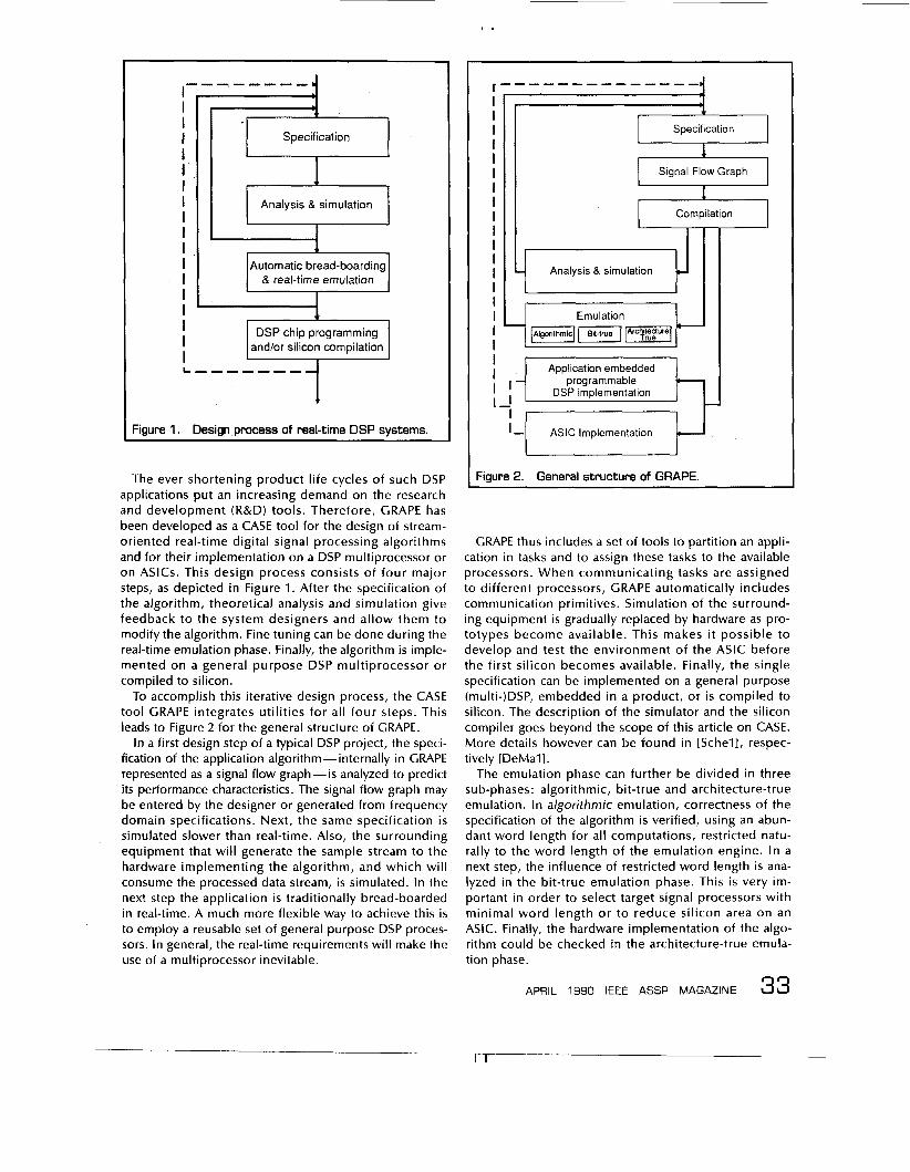
Figure 1. Design process of real-time DSP systems.
The ever shortening product life cycles of such DSP applications put an increasing demand on the research and development (R&D) tools. Therefore, GRAPE has been developed as a CASE tool for the design of stream- oriented real-time digital signal processing algorithms and for their implementation on a DSP multiprocessor or on ASICs. This design process consists of four major steps, as depicted in Figure 1. After the specification of the algorithm, theoretical analysis and simulation give feedback to the system designers and allow them to modify the algorithm. Fine tuning can be done during the real-time emulation phase. Finally, the algorithm is imple- mented on a general purpose DSP multiprocessor or compiled to silicon.
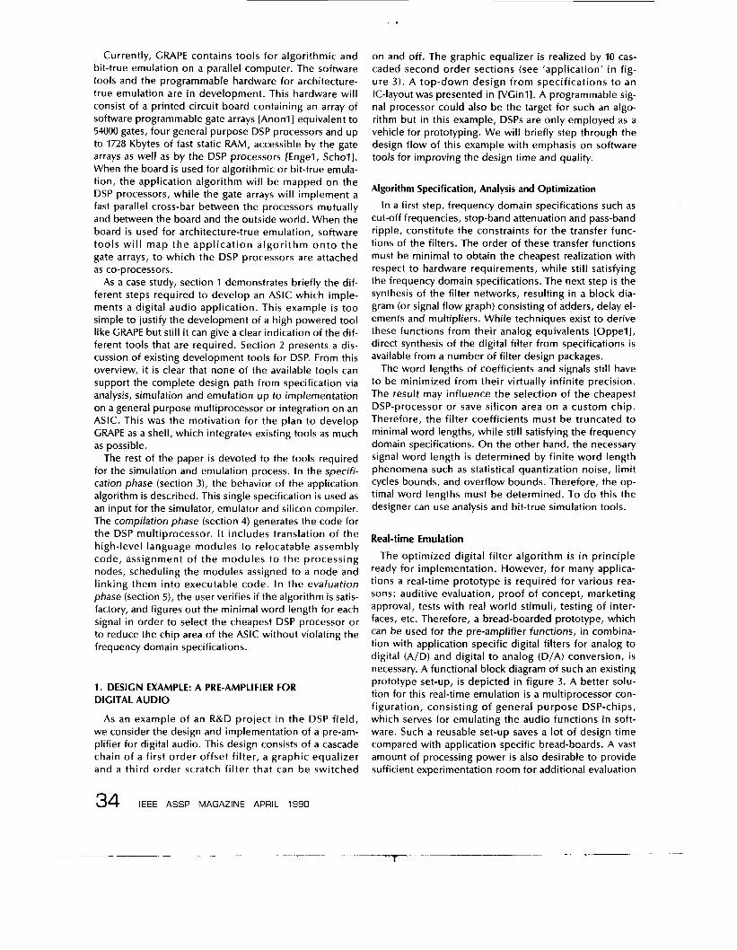
To accomplish this iterative design process, the CASE tool GRAPE integrates utilities for all four steps. This leads to Figure 2 for the general structure of GRAPE.
In a first design step of a typical DSP project, the speci- fication of the application algorithm - internally in GRAPE represented as a signal flow graph - is analyzed to predict its performance characteristics. The signal flow graph may be entered by the designer or generated from frequency domain specifications. Next, the same specification i s simulated slower than real-time. Also, the surrounding equipment that will generate the sample stream to the hardware implementing the algorithm, and which will consume the processed data stream, i s simulated. In the next step the application is traditionally bread-boarded in real-time. A much more flexible way to achieve this is to employ a reusable set of general purpose DSP proces- sors. In general, the real-time requirements will make the use of a multiprocessor inevitable.
I I I I I I I I I I I I I I I I I I I I
Specification
1
1 Signal Flow Graph
Compilation 1
I
rAigorithmiclm-1
I ~ Application embedded 1 programmable
r 1-1 ASIC Implementation
Figure 2. General structure of GRAPE.
I
GRAPE thus includes a set of tools to partition an appli- cation in tasks and to assign these tasks to the available processors. When communicating tasks are assigned to different processors, GRAPE automatically includes communication primitives. Simulation of the surround- ing equipment i s gradually replaced by hardware as pro- totypes become available. This makes i t possible to develop and test the environment of the ASIC before the first silicon becomes available. Finally, the single specification can be implemented on a general purpose (multi-)DSP, embedded in a product, or i s compiled to silicon. The description of the simulator and the silicon compiler goes beyond the scope of this article on CASE. More details however can be found in [Schell, respec- tively [DeMall.
The emulation phase can further be divided in three sub-phases: algorithmic, bit-true and architecture-true emulation. In algorithmic emulation, correctness of the specification of the algorithm is verified, using an abun- dant word length for all computations, restricted natu- rally to the word length of the emulation engine. In a next step, the influence of restricted word length is ana- lyzed in the bit-true emulation phase. This i s very im- portant in order to select target signal processors with minimal word length or to reduce silicon area on an ASIC. Finally, the hardware implementation of the algo- rithm could be checked in the architecture-true emula- tion phase.
APRIL 1990 IEEE ASSP MAGAZINE 33
Currently, GRAPE contains tools for algorithmic and bit-true emulation on a parallel computer. The software tools and the programmable hardware for architecture- true emulation are in development. This hardware will consist of a printed circuit board containing an array of software programmable gate arrays [Anonl] equivalent to 54000 gates, four general purpose DSP processors and up to 1728 Kbytes of fast static RAM, accessible by the gate arrays as well as by the DSP processors [Engel, Schol]. When the board is used for algorithmic or bit-true emula- tion, the application algorithm will be mapped on the DSP processors, while the gate arrays will implement a fast parallel cross-bar between the processors mutually and between the board and the outside world. When the board i s used for architecture-true emulation, software tools w i l l map the application algori thm onto the gate arrays, to which the DSP processors are attached as co-processors.
As a case study, section 1 demonstrates briefly the dif- ferent steps required to develop an ASIC which imple- ments a digital audio application. This example i s too simple to justify the development of a high powered tool like GRAPE but still it can give a clear indication of the dif- ferent tools that are required. Section 2 presents a dis- cussion of existing development tools for DSP. From this overview, it i s clear that none of the available tools can support the complete design path from specification via analysis, simulation and emulation up to implementation on a general purpose multiprocessor or integration on an ASIC. This was the motivation for the plan to develop GRAPE as a shell, which integrates existing tools as much as possible.
The rest of the paper i s devoted to the tools required for the simulation and emulation process. In the specifi- cation phase (section 3), the behavior of the application algorithm is described. This single specification is used as an input for the simulator, emulator and silicon compiler. The compilation phase (section 4) generates the code for the DSP multiprocessor. It includes translation of the high-level language modules to relocatable assembly code, assignment of the modules to the processing nodes, scheduling the modules assigned to a node and linking them into executable code. In the evaluation phase (section 5), the user verifies if the algorithm is satis- factory, and figures out the minimal word length for each signal in order to select the cheapest DSP processor or to reduce the chip area of the ASIC without violating the frequency domain specifications.
on and off. The graphic equalizer is realized by 10 cas- caded second order sections (see 'application' in fig- ure 3). A top-down design from specifications to an IC-layout was presented in [VGinll. A programmable sig- nal processor could also be the target for such an algo- rithm but in this example, DSPs are only employed as a vehicle for prototyping. We will briefly step through the design flow of this example with emphasis on software tools for improving the design time and quality.
Algorithm Specification, Analysis and Optimization
In a first step, frequency domain specifications such as cut-off frequencies, stop-band attenuation and pass-band ripple, constitute the constraints for the transfer func- tions of the filters. The order of these transfer functions must be minimal to obtain the cheapest realization with respect to hardware requirements, while still satisfying the frequency domain specifications. The next step is the synthesis of the filter networks, resulting in a block dia- gram (or signal flow graph) consisting of adders, delay el- ements and multipliers. While techniques exist to derive these functions from their analog equivalents [Oppell, direct synthesis of the digital filter from specifications is available from a number of filter design packages.
The word lengths of coefficients and signals st i l l have to be minimized from their virtually infinite precision. The result may influence the selection of the cheapest DSP-processor or save silicon area on a custom chip. Therefore, the filter coefficients must be truncated to minimal word lengths, while still satisfying the frequency domain specifications. On the other hand, the necessary signal word length i s determined by finite word length phenomena such as statistical quantization noise, limit cycles bounds, and overflow bounds. Therefore, the op- timal word lengths must be determined. To do this the designer can use analysis and bit-true simulation tools.
Real-time Emulation
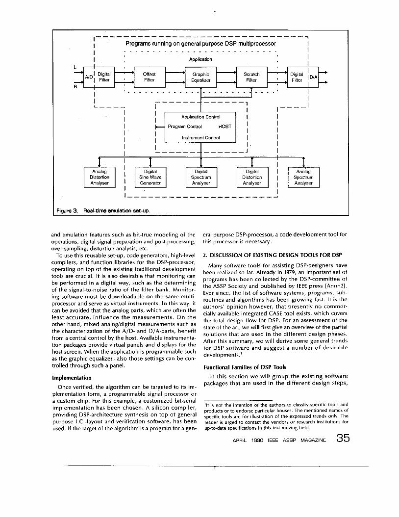
The optimized digital filter algorithm i s in principle ready for implementation. However, for many applica- tions a real-time prototype i s required for various rea- sons: auditive evaluation, proof of concept, marketing approval, tests with real world stimuli, testing of inter- faces, etc. Therefore, a bread-boarded prototype, which can be used for the pre-amplifier functions, in combina- tion with application specific digital filters for analog to digital (A/D) and digital to analog (D/A) conversion, i s necessary. A functional block diagram of such an existing prototype set-up, is depicted in figure 3. A better solu- tion for this real-time emulation is a multiprocessor con- figuration, consisting of general purpose DSP-chips, which serves for emulating the audio functions in soft- ware. Such a reusable set-up saves a lot of design time compared with application specific bread-boards. A vast amount of processing power is also desirable to provide sufficient experimentation room for additional evaluation
1. DESIGN EXAMPLE: A PRE-AMPLIFIER FOR DIGITAL AUDIO
As an example of an R&D project in the DSP field, we consider the design and implementation of a pre-am- plifier for digital audio. This design consists of a cascade chain of a first order offset filter, a graphic equalizer and a third order scratch fi l ter that can be switched
34 IEEE ASSP MAGAZINE APRIL 1990
I .
N D I Digital I Filter -
R
, - I d I D/A
’ Digital Filter , Equalizer ~ Filter ’ , Filter
’ Ofiset ’ Graphic Scratch
, ’
Figure 3. Real-time emulation set-up.
’ - - - - _ - ~ - _ _ - _ _ _ - - - _ - - - I I L-,-, I
- - - - - - - .
and emulation features such as bit-true modeling of the operations, digital signal preparation and post-processing, over-sampling, distortion analysis, etc.
To use this reusable set-up, code generators, high-level compilers, and function libraries for the DSP-processor, operating on top of the existing traditional development tools are crucial. It is also desirable that monitoring can be performed in a digital way, such as the determining of the signal-to-noise ratio of the filter bank. Monitor- ing software must be downloadable on the same multi- processor and serve as virtual instruments. In this way, it can be avoided that the analog parts, which are often the least accurate, influence the measurements. O n the other hand, mixed analog/digital measurements such as the characterization of the A/D- and D/A-parts, benefit from a central control by the host. Available instrumenta- tion packages provide virtual panels and displays for the host screen. When the application is programmable such as the graphic equalizer, also those settings can be con- trolled through such a panel.
Implementation
Once verified, the algorithm can be targeted to i ts im- plementation form, a programmable signal processor or a custom chip. For this example, a customized bit-serial implementation has been chosen. A silicon compiler, providing DSP-architecture synthesis on top of general purpose 1.C.-layout and verification software, has been used. If the target of the algorithm is a program for a gen-
I I
1 --- --- I
eral purpose DSP-processor, a code development tool for this processor is necessary.
I I
I I I I
I +
2. DISCUSSION OF EXISTING DESIGN TOOLS FOR DSP
Many software tools for assisting DSP-designers have been realized so far. Already in 1979, an important set of programs has been collected by the DSP-committee of the ASSP Society and published by IEEE press [Anon21. Ever since, the list of software systems, programs, sub- routines and algorithms has been growing fast. It is the authors’ opinion however, that presently no commer- cially available integrated CASE tool exists, which covers the total design flow for DSP. For an assessment of the state of the art, we will first give an overview of the partial solutions that are used in the different design phases. After this summary, we will derive some general trends for DSP software and suggest a number of desirable developments.’
Functional Families of DSP Tools In this section we wil l group the existing software
packages that are used in the different design steps,
Application Control I I I I
Instrument Control I I HOST ‘
I Program Control
’It i s not the intention of the authors to classify specific tools and products or to endorse particular houses. The mentioned names of specific tools are for illustration of the expressed trends only. The reader i s urged to contact the vendors or research institutions for up-to-date specifications in this fast moving field.
35 APRIL 1990 IEEE ASSP MAGAZINE
I - - - _ _ _ _ . _ _ _ _ _ _ I I I J
1 I
2 ,
conforming to the design flow of the example in sec- tion 1. Hereby, we wil l emphasize features and evolu- tions from a user’s viewpoint.
Algorithm specification, analysis and simulation tools As mentioned in the design example, the tools used
in the algorithm specification, analysis, and simulation step can be divided in two classes, namely filter de- sign packages and bit-true simulation tools.
Filter design packages Tools for digital filter design form perhaps the most
mature group of design tools, as they can rely on a lot of research results, rooted in systems theory, numeri- cal analysis, and classical network theory. Software packages such as from the IEEE [Anon21 for classical digital filters and FALCON [Gazsll for wave digital fil- ters are in fact crucial in turning the rather mathemati- cal digital filter theory into practice for the designers community. Engineering of these software already re- sulted in user friendly and integrated synthesis mod- ules such as in ILS, MatLab [Littl, Mole l l , MATRIX-X [Shahll, DFDP2, FDAS, and HYPERSIGNAL.
Most of the filter synthesis packages are able to ap- proximate classical filter structures according to e.g. butterworth and elliptic characteristics. Approxima- t ion of more arbitrary frequency responses i s also possible for magnitude [Steill or for both magnitude and phase [VdEnll. However, these tools try to ap- proximate a nominal frequency response. This i s still reminiscent to analog design practices where design centering i s desired. Because digital filters are not subject to aging and wear, filter synthesis tools should exploit the design margins between upper and lower l imits i n a tolerance diagram of the frequency re- sponse. Such techniques are, however, not yet re- ported to the authors’ knowledge.
Analysis and bit-true simulation tools A number of software environments exist that allow
for describing DSP algorithms and performing time- domain simulations, and frequency-domain analysis. One approach i s block signal oriented. In ILS, for instance, functions are modeled by separate pro- grams in sequential languages, such as FORTRAN, op- erating on blocks of signals. Feedback loops in the DSP-algorithm must be encapsulated in the programs. The other approach i s based on a netlist in terms of DSP primitives such as addition, multiplication, etc. In this way, arbitrary linear algorithms can be described wi thout programming (e.g. i n SPW, DSP-DIGEST [Clael], ODYSSEE [Covi l ] , and SILAGE [Hi l f l ] ) . This description may contain feedback loops and different sampling rates (i.e. multirate system).
An environment such as DSP-DIGEST [Clael, Clae21, which was used in the design example, gives the pos- sibi l i ty o f op t im iz ing the length o f the f i l te r co-
efficients and determing the min imum number of nonzero coefficient bits for cheap multiplier-less shift- and-add operations. In, e.g., DSP-DIGEST and the SILAGE language for DSP, different word lengths can be attached to any of the nodes, offering both bit-true simulation and analysis of quantization noise, over- flow and limit cycles [Cattl] from the same description.
For nonlinear systems, however, there i s a lack of direct analysis tools. Therefore, we are restricted to time-domain verif ication. To get an idea of the frequency-domain behavior, post-processing al- go r i t h m s, e. g . F FT, ha r m o n i c d i s t o r t i o n an a1 ys i s [VPetll and signal statistics, are available.
Traditional plotting tools, which are used to display the results of the analyses and simulations, are cur- rently enhanced w i th electronic spreadsheet l ike mathematical formulae entry (DADiSP, PCI-SNAP). In- tegration with simulation and analysis tools wil l fur- ther allow for on-line updates of the displayed curves, which results in a more interactive operation.
Real-time Emulation Tools
The previous discussion stated that two types of design tools are desirable for real-time emulation: a code development system for general-purpose DSP- processors, and an instrumentation package.
Code development systems for general purpose DSP-processors
As in the microprocessor world, the manufacturers of chips and boards make available sets of low-level development tools: assemblers, simulators and de- buggers. Time associated with the tedious assembly language programming can be saved by automatic generation of assembly code. This i s provided by filter synthesis programs such as FDAS, HYPERSIGNAL, and FALCON. This can result in rather efficient code, be- cause the block diagram i s known in advance. An- other way to save time, i s the use o f a high-level language. Recently, C-compilers became available from several DSP-chip vendors. Compilers for the SILAGE language are discussed in [Genil l and, for bit- true compilation, in this paper. The latter i s especially suited for fast prototyping. A retargetable MoDL com- piler is described in [Jacoll.
Programming time can also be saved by automating services such as I/O, file-handling, memory allocation and multi-tasking. A tool as SPOX is intended to mask those implementation details from the user by creating a ”virtual DSP” model on both the host and the real- time hardware, in combination with a mathematical C-macro library.
Instrumentation packages During the emulation, interfacing with external in-
struments i s useful for the analysis of real world data and combined digital and analog measurements
[Small]. Tools such as ASYST and SPW provide inter- faces with GPIB-based measurement setups. In addi- tion, virtual front panels and displays can be emulated on personal computers by packages such as LabView, TestTeam and PCI.
Implementation level tools
For the implementation of the algorithm, two possi- bilities exist. First, it can be realized on a general pur- pose DSP-processor. Hereby, the code development systems can be used, that were already discussed in the previous paragraph. Second, the algorithm can lead to an IC-layout. Therefore, a silicon compiler i s needed.
Silicon compilers Provided a sufficiently large market o r stringent
throughput o r size requirements, the DSP-design will be targeted to a semi-custom or full custom 1.C.- implementation. Silicon compilers specialized for DSP that assist in the layout and/or hardware architecture synthesis have been developed: (i) FIRST [Denyll and CATHEDRAL-I [Jainl l for hardwired bit-serial imple- mentation, ( i i ) LAGER [Popel l and CATHEDRAL-II [DeMal l for microcoded bit-parallel implementa- tion and (iii) CATHEDRAL-Ill [Notel l in development for hardwired bit-paral lel implementat ion. Such CAD-systems are now gradually being introduced for production use in the industry [e.g. Dela l l and wil l soon play a crucial role for the design of time critical applications.
Because of the overhead in the compiled results of these early tools, it may be s t i l l a matter o f two to four years before top-down DSP-compilers for cus- tomized silicon wil l be used for the majority of high volume designs which are critical in terms of perfor- mance or silicon area.
Trends and Requirements
From the previous discussion, we can conclude that the current DSP design tools are insufficient to offer a user-friendly design environment:
Filter design packages are lagging behind the devel- opment of the theory; most of the currently available one-dimensional filter synthesis packages are shells around programs with a functionality comparable with the IEEE programs [Anon21. Meanwhile how- ever, new one-dimensional filter structures have been invented such as wave digital filters [Fettl], LDI filters [Brutl] as well as novel filter banks [Vaydl]. Also, adaptive filters have been extensively studied and the field of multidimensional filtering is growing rapidly as well. In automatic tools, however, little of this theory i s available. Simulations nowadays require extremely long simula- tion times. Times in the order of one week or even more on supermini computers or engineering work-
~
I .
stations are no exception in industry. This i s espe- cially true with highly over-sampled systems or analog interfaces. Also, when listening tests are re- quired for evaluation of an algorithm, many opera- tions have to be performed for a few seconds of audio or video. Emulation is only possible by the expensive and time consuming method of bread-boarding the system. Neither the software nor the hardware for a reusable emulation set-up are available. The implementation of the algorithm requires assem- bly language programming or manual IC design. The different design-tools are only partial solutions. No integrated CASE tool that covers the total design flow for DSP is available.
Nowadays, however, a number of trends can be observed, which promise improvements in this situation:
Filter design packages that support the automatic de- sign of new filter types are emerging, e.g. FALCON for wave digital filters. New hardware accelerators that turn slow hosts into powerful DSP-workstations, are becoming available as uniprocessor plug-in boards and multi-processors are being worked out [Engel, Enge2, Kok.11. Manual coding for DSP-processors is being replaced by corn pi lat ion from high-level descriptions. Integrated tools that blend existing and new tools into larger design tools are becoming available. This was demonstrated with CATHEDRAL-I [Jainll, which resulted in an automated path from frequency do- main filter specifications to silicon layout.
To come to a user-friendly DSP design environment, however, some future improvements will be necessary:
The designer experience and DSP theory must also be captured in synthesis and optimization tools. This must lead to the automatic design of digital filters from arbitrary specifications expressed in a tolerance diagram and to the algorithm synthesis for non-linear functions. The code-generation tools for general-purpose DSP- processors must further be improved by optimizing the code generators and compilers. Hereby, bit-true compilers need some special attention. Also, parallel processing support for multi-DSP-processors must be worked out. The different tools must be integrated in an exten- sible CASE system with standard representation, languages, libraries and interfaces.
In the sequel, an experimental version of an integrated system is presented as example: the CASE tool GRAPE for DSP, in development for a personal computer environ- ment. While combining as much as possible available programs, the original developments within GRAPE are concentrating mainly on hitherto missing topics in DSP tool systems related with graphical programming, bit-true emulation and parallel processing support.
APRIL 1990 IEEE ASSP MAGAZINE 37
l ' l -
I .
3. SPECIFICATION OF DSP ALGORITHMS
Specification languages for DSP algorithms may be di- vided in three sub-classes: sequential languages, func- tional languages and graphical techniques [Lauwll (see also the box on 'Languages for DSP multiprocessors').
The use of a conventional sequential language (C, For- tran, Pascal,. . .) may seem the most obvious approach due to i t s widespread use, to the availability of compilers for almost all target processors and to the large libraries with useful modules that already exist. However, both the ASIC implementation as well as the emulation on a DSP multiprocessor allow for the concurrent execution of multiple tasks. Sequential languages mask the inher- ent parallelism of the application. A parallelizing com- piler is thus needed to extract the data dependency graph out of the sequential program description [Whitl]. The construction of such a compiler i s a very complex task and, up to now, they are only able to find part of the implicit parallelism in the program [Colll].
To be able to extract the data dependency graph auto- matically by a compiler out of a textual representation of a program, we need a high-level language which forbids the use of constructs masking or introducing data depen- dencies not implied by the program itself. In short, we need a language that textually describes the data depen- dency graph. Functional languages possess this property [Agerl, Davill. Silage, for example, i s a functional lan- guage that has been designed specifically to describe DSP applications [Hilf l l . One of its distinct features is that it allows the user to specify the word length of each sig- nal. Maybe the only drawback of functional languages is that they st i l l represent the program as a sequential list of statements, although the order in which the statements occur i s irrelevant. Indeed, execution order is completely determined by the data dependencies.
The third method i s the use of graphical techniques, where the data dependency graphs are directly drawn by the system designers. This technique closely resembles the intuitive way they look at the application and think about its behavior. This is especially true for DSP applica- tions where system designers are already used to devel- oping signal flow graphs or block diagrams [Lee.ll. As a consequence, some graphical systems for programming DSP algorithms already exist. Texas Instruments, for in- stance, offers a graphical environment for programming their Odyssee system, a multiprocessor built up of sev- eral digital signal processors of the TMS320xx family [Covil]. Their graphs represent the z-transform diagrams of the filter algorithms to be implemented. Another ex- ample i s an internal experiment at Hewlett-Packard, where graphical tools for drawing Nassi-Schneidermann diagrams were offered to various programming pools [Dea.l]. These systems showed, however, that at the low- est level of detail, graphical programming becomes clumsy and dreadful.
From this overview it is clear that a mixed graphical and textual representation of the algorithm is desirable. On the highest levels in programming hierarchy the signal
38 iEEE ASSP MAGAZINE APRIL 1990
A first class of languages for DSP is formed by the conventional sequ (Fortran, Pascal, C, . . .) originally deve Neumann uniprocessors [Goldll. Th common property that instructions are same way as they will be executed on cessor. During execution, a program through the l i s t of instructions by sim
not execute an instruction of which one i s not yet computed (e.g. most common method fo
constructs a data dependency gra The nodes of a data dependency structions; the edges indicate t between an instruction that prod a consuming instruction which n
on the screen and to use thi as the programming language graphical programs i s that th
ism and the other to express the sequ
of these graphical progr natural conservatism of
flow graphs for representing their al
_- - 1'1
I .
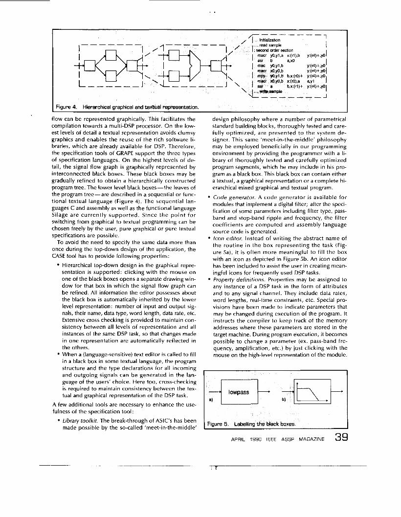
flow can be represented graphically. This facilitates the compilation towards a multi-DSP processor. On the low- est levels of detail a textual representation avoids clumsy graphics and enables the reuse of the rich software li- braries, which are already available for DSP. Therefore, the specification tools of GRAPE support the three types of specification languages. On the highest levels of de- tail, the signal flow graph is graphically represented by interconnected black boxes. These black boxes may be gradually refined to obtain a hierarchically constructed program tree. The lower level black boxes-the leaves of the program tree-are described in a sequential or func- tional textual language (Figure 4) . The sequential lan- guages C and assembly as well as the functional language Silage are currently supported. Since the point for switching from graphical to textual programming can be chosen freely by the user, pure graphical or pure textual specifications are possible.
To avoid the need to specify the same data more than once during the top-down design of the application, the CASE tool has to provide following properties:
Hierarchical top-down design in the graphical repre- sentation i s supported: clicking with the mouse on one of the black boxes opens a separate drawing win- dow for that box in which the signal flow graph can be refined. All information the editor possesses about the black box is automatically inherited by the lower level representation: number of input and output sig- nals, their name, data type, word length, data rate, etc. Extensive cross checking is provided to maintain con- sistency between all levels of representation and all instances of the same DSP task, so that changes made in one representation are automatically reflected in the others. When a (language-sensitive) text editor i s called to fill in a black box in some textual language, the program structure and the type declarations for all incoming and outgoing signals can be generated in the lan- guage of the users’ choice. Here too, cross-checking is required to maintain consistency between the tex- tual and graphical representation of the DSP task.
A few additional tools are necessary to enhance the use- fulness of the specification tool:
Library toolkit. The break-through of ASIC’s has been made possible by the so-called ’meet-in-the-middle’
design philosophy where a number of parametrical standard building blocks, thoroughly tested and care- fully optimized, are presented to the system de- signer. This same ’meet-in-the-middle’ philosophy may be employed beneficially in our programming environment by providing the programmer with a li- brary of thoroughly tested and carefully optimized program segments, which he may include in his pro- gram as a black box. This black box can contain either a textual, a graphical representation or a complete hi- erarchical mixed graphical and textual program.
Code generator. A code generator i s available for modules that implement a digital filter; after the speci- fication of some parameters including filter type, pass- band and stop-band ripple and frequency, the filter coefficients are computed and assembly language source code is generated. /con editor. Instead of writing the abstract name of the routine in the box representing the task (Fig- ure sa), it i s often more meaningful to fill the box with an icon as depicted in Figure 5b. An icon editor has been included to assist the user in creating mean- ingful icons for frequently used DSP tasks. Property definitions. Properties may be assigned to any instance of a DSP task in the form of attributes and to any signal channel. They include data rates, word lengths, real-time constraints, etc. Special pro- visions have been made to indicate parameters that may be changed during execution of the program. It instructs the compiler to keep track of the memory addresses where these parameters are stored in the target machine. During program execution, it becomes possible to change a parameter (ex. pass-band fre- quency, amplification, etc.) by just clicking with the mouse on the high-level representation of the module.
I I
l t - I I I
APRIL 1990 IEEE ASSP MAGAZINE 39
I .
All together, the utilities of the specification tool make it possible to describe an application easily and accurately. The single specification can then be used as an input for the simulator, the emulator or the silicon compiler, pro- vided Silage is used for the textual parts.
4. COMPILATION FOR A DSP MULTIPROCESSOR EMULATION FACILITY
Once the modular specification for a given application has been completed, GRAPE provides for tools to transform this DSP algorithm into executable code for the available DSP multiprocessor architecture.
In a first step, each of the modules specified in a high- level language is translated into relocatable assembly code. Currently, GRAPE supports the translation of speci- fications in C and SILAGE.
The next step is of particular importance, whenever real- time emulation is required. Using estimates of the compu- tation time for each module (extracted by examining the assembly language representation of the modules) and of the inter-module communication requirements, the parti- tioner assigns the modules to the available hardware resources in order to minimize the interprocessor com- munication. Note that the partitioner has specifically been included in GRAPE to support parallel processing. The tool can be bypassed when code is generated for a uniprocessor.
The next step in the transformation provides for appro- priate scheduling of the tasks assigned to a single pro- cessing node in the previous step. Besides determining the order in which the tasks assigned to a node have to be executed-this i s done by examining the data depen- dency graph-the scheduler adds communication mod- ules to control the ADCs and DACs and to establish interprocessor communication. Scheduling is followed by a post-optimization step that optimizes the use of the internal processor registers by analyzing the life-time of the variables.
Finally, the individual (relocatable) assembly language modules for each of the processing nodes, are linked to- gether, resulting in the executable code for each of the available processors. In the remainder of this section, the design of a bit-true compiler for the applicative language SILAGE i s discussed in more detail. Currently, the com- piler produces code for the Motorola 56001 DSP processor [Anon31. The description of other optimizing compilers for general purpose signal processing may be found in [Genill and [Jacoll.
A straightforward- but time consuming-approach to the generation of bit-true code would be to provide an appropriate mask for the result of each computation per- formed in the generated code. In the compiler described above, a special technique has been applied based on an appropriate representation of the numeric data in the generated program, i.e. by cleverly placing the data in the internal accumulator of the DSP processor, we can avoid the extra overhead required for masking the result
of a bit-true computation. Additional instructions ensur- ing bit-true computation are only incorporated in the assembler program; at the moment an explicit type- conversion-i.e., a change in data word length-is per- formed in the corresponding Silage program.
5. VERIFICATION O F THE DSP ALGORITHM
At this point the algorithm that must be emulated has been specified and compiled (bit-true or not) for a DSP multiprocessor. The only task left for GRAPE is to provide tools to verify if the algorithm itself is satisfactory and to verify, e.g., the minimal word length for each signal in or- der to reduce the chip area of the ASIC without violating the distortion specifications.
This verification may cover a number of aspects:
Verification of the correctness of the developed algo- rithm (algorithmic emulation). Typically, all the corn- putations in this step are performed using an abundant word length. Investigation of the influence of a restricted word length (bit-true emulation). In this step, all the corn- putations in the emulated algorithm are performed with a restricted word length. Verification of the real-time behavior of the given al- gorithm (real-time emulation). Verif icat ion of the hardware implementat ion (architecture-true emulation).
To accomplish these verification tasks, the user must
apply signals to the emulator and to control their characteristics; measure the output signals coming from the emula- tor, to gather statistics of these signals and to corn- pare them with the specifications;
be able to
change parameters of the emulated algorithm.
Three special tools are being integrated in the graphi- cal programming environment GRAPE to accomplish these verification tasks:
From within GRAPE, wave-form generators and mea- suring instruments are directly controlled. The set- tings of these instruments are manipulated via pop-up front panels and are communicated to them via an I EEE-488 interface bus. A software library of virtual instruments such as wave-form generators, spectrum analyzers, data log- gers, distortion analyzers, etc. is available. Indeed, instead of employing separate measuring instru- ments, it is possible, depending on the signal data rate, to program their function in software and im- plement these measuring modules together with the applicatilon algorithm on the same multiprocessor system. Also, for these virtual instruments, pop-up front panels are used for controlling their parameters. It i s possible to design pop-up front panels for the application algorithm that runs on the multiproces-
I .
sor. For example, a front panel may be designed for a digital amplifier that mimics a linear potentiometer. Using these front panels, the user can interactively change the parameters of the algorithm and verify their effect in real-time.
CONCLUSION
This article discussed the usefulness of CASE tools for the design and implementation of stream-oriented real- time DSP applications. The design process of a typical DSP ASIC was analyzed and an indication was given of the development tools that could speed-up the project or improve i t s quality. A systematic overview of existing de- velopment tools was presented next. From this overview, it i s clear that no CASE tool exists which covers the whole design process starting from specification via analysis, simulation and real-time emulation up to implementation on a general purpose programmable DSP multiprocessor or integration on silicon. The article then presented the CASE tool GRAPE that aims at filling this gap. This can be achieved by using state-of-the-art techniques for graphi- cal programming, for the code generator, the bit-true compiler, the multiprocessor partitioner, the scheduler, the virtual instrument controller and the silicon compiler. In the near future, GRAPE will be enhanced with tools to enable architecture-true emulation of an ASIC on an ar- ray of programmable gate arrays.
REFERENCES
[Ackell W. Ackerman, “Data Flow Languages,” Com- puter, Feb. 1982, pp. 15-25.
[Agerl] Agerwala T., Arvind, ”Data Flow Systems. Guest Editors’ Introduction,” Computer, Feb. 1982, pp. 10-13.
IAho.11 A. Aho, R. Sethi and J. Ullman, “Compilers: Prin- ciples, Techniques and Tools,” Addison-Wesley Publ. Co., 1986.
[Anonll Anonymous, “PGA Data Book,” Advanced Micro Devices, 1988.
[Anon21 Anonymous, ”Programs for digital signal pro- cessing,” Digital Signal Processing Committee, /€€€ Press, 1979.
[Anon31 Anonymous, “Motoro la DSP56000, user’s guide,“ Motorola Inc., 1986.
[Brut] L. T. Bruton, ”Low sensitivity digital ladder filters,” I € € € Transactions on Circuits and Systems, vol. CAS-22,
[Cattl] F. Catthoor, Hugo De Man, and J . Vandewalle, “Simulated-annealing based optimization of coefficient and data word lengths in digital filters,” lnternational lournal of Circuit Theory and Design, vol. 16, 1988.
[Caral] M.G. Carasso, J. B. H. Peek and J. P. Sinjou, ”The compact disc digital audio system,” Philips Technical Review, vol. 40, no. 6, pp. 151-155, 1982.
[Clael] L. Claesen, F. Catthoor, H. De Man, J. Vande- walle, S. Note and K. Mertens, “A CAD environment for the thorough analysis, simulation and characteriza- tion of VLSl implementable DSP systems,” Proceedings
pp. 168-176,1986.
O f I€€€-lCCD’86, pp. 72-75, Oct. 1986. [Clae21 L. Claesen e.a., ”DIGEST: a digital filter evalu-
ation and simulation tool for MOSVLSI filter implemen- tations,” I € € € Journal of Solid-state Circuits, vol. SC-19, no. 3, June 1984.
[Coll l l Collesidis R., Dutton T., Fisher J., Metcalf W., “ Co n t r o I of m u It i p r o ce s s o r S PS - 1 000 con f i g u rat i o n s using principles of data flow architecture,” Signal Pro- cessing Systems Inc., 223 Crescent Street, Waltham, Massachussetts 02154, USA.
[Covill C. Covington et al., “Multiple digital signal pro- cessing environment for intelligent signal processing,” Internal Report of the Speech and Image Understand- ing Laboratory, Computer Science Centre, Texas In- struments, 1987.
Davill Davis A., Keller R., “Data flow program graphs,” Cornputer, Feb. 1982, pp. 26-30.
Dea.11 R. Dea, V. D’Angelo, “P-Pods: A software graphi- cal design tool,” Hewlett-Packard Journal, March 1986,
[Delall A. Delaruelle, “Design of a syndrome generator chip using the PIRAMID design system,” Digest of Techn. Papers, ESSCIRC‘88, Sept. 1988.
[DeMal l H. De Man, J . Rabaey, P. Six, L. Claesen, “Cathedral-ll: A silicon compiler for digital signal pro- cessing,” /€€€ Design & Test, Dec. 1986, pp. 13-25.
[Denyl l P.D. Denyer, D. Renshaw, N. Bergmann, “A silicon compiler for VLSl signal processors,” Digest o f tech. papers. ESSCIRC’82, (Brussels, Belgium), pp. 215-218, Sept. 1982.
[Engell M. Engels, R. Lauwereins, J. Van Ginderdeuren, ”Concept and implementation of a powerful multipro- cessor system for digital signal processing,” lnternal Report KUL-€SAT 7989, Jan. 1989.
[Enge2] M. Engels, R. Lauwereins, J. Peperstraete, “Analysis of Interconnection networks for a multipro- cessor DSP simulator,” Int. Symp. on Mini- and Micro- computers and their Applications, Zurich, Switzerland, June 26-29,1989.
[Fettl] A. Fettweis, ”Wave digital filters: theory and prac- tice,” Proc. I € € € , vol. 74, no. 2, pp. 270-327, Feb. 1986.
[Gazsl] L. Gazsi, “Explicit formulae for lattice wave digital filters,” I € € € Trans. Circuits and Systems, vol. CAS-32, pp. 68-88, Jan. 1985.
[Gen i l ] D . Genin, J . D e Moor te l , D . Desmet and E. Van de Velde, “System design, optimization and in- telligent code generation for standard digital signal processors,“ Proceedings ISCAS‘89, pp. 565-569, May 1989.
[Goldl] H. Goldstine, J. Von Neumann, “On the prin- ciples of large computing machines,” unpublished pa- per (7946), included in John von Neumann: Collected Works, Ed. Taub A., Design of Computers, Theory of Automata and Numerical Analysis, Pergamon Press, vol. V, 1963, pp. 1-32.
[Hi l f l ] P. Hilfinger, “A high-level language and silicon compiler for digital signal processing,” Proc. / € € E ClCC Conf., May 1985, pp. 213-216.
pp. 32-35.
I .
[Ho . .~ ] Wai H. Ho, Edward A. Lee, David G. Messer- schmitt, “High level data flow programming for digital signal processing,” VLSI Signal Processing 111, IEEE Press, Nov. 1988, pp. 385-395.
[Howell C. Howe, B. Moxon, “How to program parallel processors,” /E€€ Spectrum, Sept. 1987, pp. 36-41.
[Jacoll E. Jacobs, “A microcode generator in MoDL for the pPD7720 digital signal processor,” Technical Re- port 87C074, University of Twente, The Netherlands, 1987.
[Jainll R. Jain e.a., ”Custom design of a VLSl PCM-FDM transmultiplexer from system specifications to circuit layout using a computer-aided design system,“ / € E € JSSC, vol. SC-21, Feb. 1986.
iKok.11 W. Kok, A. Yeung, P. Hoang, J . Rabaey, “A multiprocessor system for DSP behavioral simulation,’, VLSl Signal Processing 111, IEEE Press, 1988, pp. 295-306.
[Lauwll R. Lauwereins, “Design of an argument f low parallel computer: f rom program prganization to multiprocessor architecture,” Ph.D. Diss., KUL-ESAT, Feb. 1989.
[Lee.ll E. A. Lee, D. C. Messerschmitt, ”Pipeline inter- leaved programmable DSP’s: synchronous data flow programming,” / E € € Trans. on Acoustics, Speech & Signal Processing, vol. ASSP-35, no. 9, Sept. 1987, pp. 1334-1345.
[Littll I . N. Little, “PC-MATLAB, user’s guide,” The Math- Works, Inc., 158 Woodland SL., Sharborn, MA 01770.
[Mole l l C. Moler, “MATLAB user’s guide,” Dept. of Computer Science, University of New Mexico, 1980.
[ N o t e l l S. Note, J . Van Meerbergen, F. Catthoor, H. De Man, ”Automated synthesis o f a high speed CORDIC algorithm with the CATHEDRAL-Ill compila- tion system,“ Proceedings IEEE lSCAS’88, June 1988.
[Oppell A.V. Oppenheim and R. W. Shafer, “Digital sig- nal processing,” Prentice Hall Inc., New Jersey, 1975.
[Popell S. Pope, J. Rabaey and R. W. Brodersen, ”Auto- mated design of signal processors using macrocells,” VLSl Signal Processing, IEEE Press, pp. 239-251,1984.
[Schell C. Scheers, “User manual for the S2C Silage to C Compiler,” lnternal Report, IMEC, Leuven, Belgium, Nov. 1988.
[Scholl K. Schoofs, Ch. Verheirstraeten, ”Design and im- plementation of a flexible DSP multiprocessor board using programmable gate arrays,” M.Sc. Diss., KUL- ESAT Sept. 1989 (in Dutch).
[Shahll S. Shah e.a., ”MATRIXx: A model building, non- linear simulation and control design program,” in Computer-Aided Control Systems Engineering (M. Jamshidi e.a eds.), North-Holland Publishing, pp. 181- 207,1985.
[Small] C. H. Small, ”Virtual instruments,’’ EDN, pp. 121- 128, Sept. 1988.
[Steill K. Steiglitz, “Computer-aided design of recursive digital filters,” / E € € Trans. Audio Electroacoustics, vol. AU-18, pp. 123-129, June 1970.
[Trelll P. Treleaven, I. Gouveia Lima, “Fifth generation computers,‘’ Computer Physics Communications,
North Holland Publishing Company, vol. 26, 1982,
[Vaydl] P. P. Vaidyanathan, “A tutorial on multirate digital filter banks,” Proceedings ISCAS’88, pp. 2241-2248.
[VGinl] J . Van Ginderdeuren, H. De Man, B. De Loore, H. Vanden Wijngaert, A. Delaruelle, C . Van Den Audenaerde, “A High Quality Digital Audio Filter Set Designed by Silicon Compiler CATHEDRAL-I ,I’ Journal of Solid-state Circuits, vol. SC-21 , pp. 1062-1075, Dec. 1986.
[VPetll P. Van Petegem, P. Vandeloo and W. Sansen, “Ef- ficient least-mean-squares algorithm performs audio distortion analysis on sampled waveform,” Proceedings of 75th AES Convention, Paris, March 1984.
[VdEnl] A. W. M. van den Enden and G.A. L. Leenknegt, “Design of optimal I IR filters with arbitrary amplitude and phase requirements,“ Philips Research Internal Re- port 6090, 1986.
[Whitl] Whitelock P., “A conventional language for data flow computation,” M.Sc. Diss., Department of Com- puter Science, University of Manchester, UK, Oct. 1978.
pp. 277-283.
Rudy Lauwereins received the degree in elec- trical engineering from the Katholieke Univer- siteit Leuven in 1983 and a Ph.D. in Applied Sciences in February 1989. He is currently a senior research assistant at the ESAT labora- tory of the Katholieke Universiteit Leuven in Belgium. His main research interest i s the large domain of parallel processing, includ- ing fault-tolerant computations and real-time signal processing. His work is sponsored by
the Belgian National Fund for Scientific Research.
~
Marc Engels received the electrical engineer- ing degree from the Katholieke Universiteit Leuven in Belgium in 1988. He joined the ESAT laboratory as a research assistant, where he is currently working towards a Ph.D. de- gree. His main activity i s the design of recon- figurable multiprocessor networks; he i s also involved in the development of a case tool for these multiprocessors. His work i s spon- sored by the Belgian Institute for Scientific
Research in Industry and Agriculture.
Jean Peperstraete received the degree in Elec- trical Engineering, Industrial Engineering and a Ph.D. from the Katholieke Universiteit Leu- ven, Belgium, in 1964, 1968 and 1973 respec- tively. He was a design engineer and group leader at Philips Industries and is now Profes- sor of Digital Electronic Systems at the Katho- lieke Universiteit Leuven. His areas of interest include Computer Architectures, Transput- ers, data flow and parallel computers.
I .
Eric Steegmans has been the first assistant at the Computer Science Department of the Katholieke Universiteit Leuven since Octo- ber 1985. His research activities include com- piler construction, formal specifications and software engineering techniques. He lec- tures on software engineering, database management and artificial intelligence in postgraduate courses at the Katholieke Uni- versiteit Leuven and Limburg, U.C. Both his
engineering degrees in Computer Sciences (1978) and his Ph.D. are from the Katholieke Universiteit Leuven. From 1978 to 1985 he was engaged in several research projects at the Computer Science De- partment of the Katholieke Universiteit Leuven.
johan Van Cinderdeuren received the electri- cal engineering degree from the Katholieke Universiteit Leuven, Belgium, in 1980. During the summer of 1980, he was on leave at Philips Research Laboratories, Eindhoven, The Netherlands. From autumn 1980 to 1983 he obtained an IWONL grant that allowed him to work as a research assistant at the ESAT Laboratory of the Katholieke Uni - versiteit Leuven. In 1983 he was appointed as
research assistant under the ESPRIT 97 (Advanced Algor.ithms and Architectures for DSP) project on the CATHEDRAL system at the Katholieke Universiteit Leuven and the Inter-University Micro Elec- tronics Center (IMEC), Leuven, respectively. In 1986, he joined Philips Industrial Activities in Leuven, Belgium. His current interests are in computer-aided design and 1.C.-implementations strategies for DSP, which he has applied in several digital audio applications. He i s also leading a campus-liaison group of PHILIPS stationed at IMEC.
TRADEMARKS
I LS
MATRl X-X
DFDP2
FDAS
HY PERS IGNAL s PW
PC I -S NAP DADISP
S P O X
ASYST
TESTTEAM LABVIEW
i s a trademark of Signal Technology, Inc. is a trademark of Integrated Systems, Inc. is a trademark of Atlanta Signal Pro- cessors, Inc. i s a trademark of Momentum Data Systems is a trademark of Hyperception, Inc. is a trademark of Comdisco Systems, Inc. i s a trademark of Siemens is a trademark of DSP Development Corporation i s a trademark of Spectron M ic ro Systems is a trademark of Asyst Software Tech- nologies, Inc. i s a trademark of Philips-Fluke is a trademark of National Instruments Co rporat ion
NEURAL NETWORKS 1989
8 New Tutorial Videotapes presented by
IEEE's Educational Activities Board in Cooperation with the
IEEE Neural Network Committee
ADAPIlVE PA'ITERN RECOGNITION - Lton Cooper NEUROBIOLOGY REVIEW - 1989 -Walter Freeman ADAPTIVE SENSORY - MOTOR CONTROL - Stephen Grossberg NEURAL NETWORKS: ALGORITHMS AND MICROHARDWARE! -John Hopfield VLSI TECHNOLOGY AND NEURAL NETWORK CHIPS - Lawrence Jackel OPTICAL NEUROCOMPUTERS - 1989 - Demetri Psaltis SARTING A HI-TECH COMPANY - Peter Wallace REINFORCEMENT LEARNING - Ronald Williams
For more information, call IEEE, Educational Activities at (201) 562-5499, or write IEEE, Educational Activities 445 Hoes Lane, PO Box 1331 Piscataway, NJ 08855-1331.
Introduction to
DIGITAL SPEECH PROCESSING
Developed by Andrew Sekey I A smooth transition from the fundamentals of speech production to modern applications!
IEEE MEMBER PRICE $249.00, List Price $695.00
ILP includes study guide, audiotape, textbook, Digital Processing of Speech Signals, Lawrence R. Rabiner and Ronald W. Schafer, Prentice-Hall, 1978, and an IEEE Press Book, Speech Analysis, ed. Ronald W. Schafer and John D. Markel, IEEE, 1979.
For more information call: --- (201) 562-5498, or write
\ . - -- . \
e- 1, '\ \ ' ' ---\ '1 '\ \\ -.\
Theresa M. Kirby \ \ \ '\ i Educational Activities U' \ 1
I \ ' \ t P.O. IEEE Box 1331 \ I \ ! ! 445 Hoes Lane Piscataway, NJ 08855-1331
' 1 ; ; / I I
APRIL 1990 IEEE ASSP MAGAZINE 43