
Dag fm ifma kluwer_27-03-14_manu matthyssens_hedendaagse fm inkoopaanpak
8/7/2019 FM 8-50 1940
http://slidepdf.com/reader/full/fm-8-50-1940 1/94
MHI \ Act
Copy 3 FM 8-50
WAR DEPARTMENT
MEDICAL FIELD MANUAL
SPLINTS, APPLIANCES,
AND BANDAGES
8/7/2019 FM 8-50 1940
http://slidepdf.com/reader/full/fm-8-50-1940 2/94
FM 8-50
MEDICAL FIELD MANUAL
SPLINTS, APPLIANCES, AND
BANDAGES
Prepared under direction of
The Surgeon General
UNITED STATES
GOVERNMENT PRINTING OFFICE
WASHINGTON: 1940
For sale by the Superintendent of Documents. Washington,D. C. - Price 20 cents
8/7/2019 FM 8-50 1940
http://slidepdf.com/reader/full/fm-8-50-1940 3/94
WAR DEPARTMENT,WASHINGTON, September 11, 1940.
FM 8-50, Medical Field Manual, Splints, appliances, andbandages, is published for the information and guidance ofall concerned.
[A. G. 062.11 (6-12-40).]
BY ORDER OF THE SECRETARY OF WAR:G. C. MARSHALL
Chief of Staff.OFFICIAL:
E. S. ADAMS,Major General,
The Adjutant General.
1[
8/7/2019 FM 8-50 1940
http://slidepdf.com/reader/full/fm-8-50-1940 4/94
TABLE OF CONTENTS
SECTION I. GENERAL. Paragraph PagePurpose and scope-----____-- ___-__ 1 1
II. SPLINTING FRACTURES FO R TRANSPOR-TATION.
General -- ______________________ 2 2
Army hinged half-ring thigh and legsplint __--- __-_------------------- 3 2
Splint strap, adjustable traction_.__ 4 4Splint support and footrest_-_______ 5 4Immobilization for transportation of
major fractures of lower extremity_ 6 9Emergency treatment and transpor-
tation of fracture of spine-_______ 7 12
Wire ladder splint_-- …______--_____ 8 14Thomas splint, arm-hinged_---__-- _ 9 15Basswood splint -_--_--____ -_______0 18Prevention and early treatment of
traumatic shock ----____--- _____ 11 18III. SPLINTS AND APPLIANCES USED IN DEFINI-
TIVE CARE OF BONE AND JOINTINJURIES.
General ------------------------ _-- 12 20Definitive treatment of fractures___ 13 21Balkan frame _______---____--._____ 14 22Skin traction ----------- ---------_ 15 27Steinmann extension apparatus___ 16 29Skeletal suspension and traction_____ 17 29Wire apparatus -__-____ ____--___--_ 18 30Skeletal fixation of proximal and dis-
tal fragments ____---- ___--- _____ 19 30Attachment Pierson ------ _-------_ 20 32Cabot splint -----_----. ___----_-- 21 35Aluminum cock-up wrist splint-_____ 22 37T-splint for fractured clavicle_______ 23 38Aeroplane or abduction splint______ 24 40Basswood splint_-_-----___--- _____ 25 42Plaster of paris -__________________ 26 44Plaster casts-______________----_-__ 27 45Pipe frame and hammock for hyper-
extension body cast---- ___---_--- 28 46
Compression fractures of spine --____ 29 49Fracture or dislocation of cervical
spine ____--- ___----------------- 30 50IV. BANDAGES AND DRESSINGS.
General __------------------------- 31 52
Rules for bandaging --------__----- 32 54Application of bandages and theiruses--------------- ------------- 33 55
Dressings __----_----------___ ---. 34 81Appendix ------.------------ ---.........--- --- 89
m
8/7/2019 FM 8-50 1940
http://slidepdf.com/reader/full/fm-8-50-1940 5/94
FM 8-50
MEDICAL FIELD MANUAL
SPLINTS, APPLIANCES, AND BANDAGES
SECTION I
GENERAL
* 1. PRPOSE AND ScoPE.--a. The purpose of this manual is
to place in the hands of the medical officer a guide for in-
struction of medical personnel in application of bandages,
dressings, splints, and appliances. It should enable him to
organize his instruction so as to convey information which
may be utilized by medical personnel in their various tasks
pertaining to care of the surgical patient whenever appli-
cation of splints, bandages, or dressings is required. Illus-
trations show bandages, dressings, splints, and appliances
and procedure for their application. The illustrations may
be transferred onto charts but preferably instruction should
be carried out by actual demonstrations. Therefore, thismanual serves as a practical time-saving guide for instruc-
tion and not as complete information in care and treatment
of wounds or fractures. It includes such description and
nomenclature of those splints and appliances as will provide
adequate treatment and which adhere to designs that meet
the following qualifications:
(1) Efficiency and correct mechanical methods.
(2) Simplicity of design and low cost of construction.(3) Transportability in order that an efficient splint may
be applied and remain in situ until the patient reaches the
hospital for definitive care. In some instances, changes in
type of splint used may not be necessary even at the fixed
hospital.
(4) Quick manufacture and easy distribution.
(5) Combination of traction and fixation in the same
apparatus.(6) Constancy of type and simplicity of mechanical pro-
cedure making it readily understood and easily applied.
b. Section II deals with splints and appliances such as may
be applied by enlisted personnel of the Medical Department
1
8/7/2019 FM 8-50 1940
http://slidepdf.com/reader/full/fm-8-50-1940 6/94
1-3 MEDICAL FIELD MANUAL
so as to assure fixation and traction, thereby reducing chancesof infection and minimizing pain and shock during transpor-
tation. Splints and appliances and their application as usedin transportation of fractures, including certain splints used
in definitive treatment, are illustrated.
c. Section III deals with those splints and appliances used
in the definitive care of fractures.d. Section IV deals with description and use of various types
of bandages and dressings.
e. Certain of the splints are standard items of supply, othersare nonstandard, and still others are splints and applianceswhich may be made at a local hospital by
using specificationsgiven.
SECTION II
SPLINTING FRACTURES POR TRANSPORTATION
* 2. GENERAL.-The necessity for splinting fractures before
transportation is attempted cannot be overestimated. It les-
sens pain, shock, and additional damage to bones and softparts. Compound fractures are not further contaminated,shortening is prevented, and reduction is made less difficult.
The primary mortality rate of 50 percent in compound frac-tures of the femur in the British Army during the World
War was reduced to 15 percent by proper splinting alone.Every major fracture in the long bones should be splintedwhere they lie before transportation is attempted. Proper
splinting of peacetime fractures is equally as essential as care
of wartime injuries.
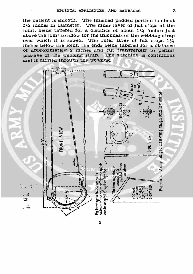
* 3. ARMY HINGED HALF-RING THIGH AND LEG. SPLINT (fig.
1).-a. Description.-(1) The side arms of the splint aremade of 3/s-inch cold rolled or Bessemer steel rod; the halfring of the same material, 1/2 inch in diameter.
(2) The half ring is covered with an inner layer of '/2 -inchfelt and an outer layer of A/4-inch felt. The felt is covered
with first-cut horsehide, cream color, not oiled or dressed,and free from material that might irritate the skin. Theleather is neatly and securely sewed with waxed linen thread,using a baseball stitch (about four to the inch). The cover-ing is so stitched that the surface coming in contact with
2
8/7/2019 FM 8-50 1940
http://slidepdf.com/reader/full/fm-8-50-1940 7/94
SPLINTS, APPLIANCES, AND BANDAGES 3
the patient is smooth. The finished padded portion is about
11/4 inches in diameter. The inner layer of felt stops at thejoint, being tapered for a distance of about 1 /4 inches justabove the joint to allow for the thickness of the webbing strapover which it is sewed. The outer layer of felt stops 11/4
inches below the joint, the ends being tapered for a, distance
of approximately 2 inches and cut transversely to permit
passage of the webbing strap. The stitching is continuous
and is carried through the webbing.
.J aL
/ .
-
LUC
_,, -. t' ? r
3
8/7/2019 FM 8-50 1940
http://slidepdf.com/reader/full/fm-8-50-1940 8/94
3-5 MEDICAL FIELD MANUAL
b. Uses.--(1) Transportation. Fixed traction treatmentof-
(a) Fractures of the femur.
(b) Fractures and injuries of the knee.(c) Fractures of the tibia above the ankle.(2) Definitive care.-Suspension traction treatment of-
(a) Fractures of the femur.(b) Fractures of the tibia and fibula.(c) Other injuries and orthopedic conditions of the lower
extremity.
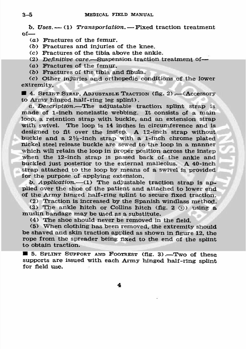
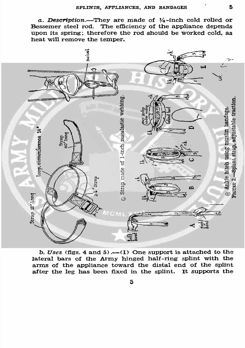
* 4. SPLINT STRAP, ADJUSTABLE TRACTION (fig. 2) .- (Accessory
to Army hinged half-ring leg splint).a. Description.-The adjustable traction splint strap is
made of 1-inch nonelastic webbing. It consists of a mainloop, a retention strap with buckle, and an extension strapwith swivel. The loop is 14 inches in circumference and isdesigned to fit over the instep. A 12-inch strap withoutbuckle and a 21/2-inch strap with a 1-inch chrome platednickel steel release buckle are sewed to the loop in a manner
which will retain the loop in proper position across the instep
when the 12-inch strap is passed back of the ankle andbuckled just posterior to the external malleolus. A 40-inchstrap attached to the loop by means of a swivel is providedfor the purpose of applying extension.
b. Application.-(1) The adjustable traction strap is ap-plied over the shoe of the patient and attached to lower endof the Army hinged half-ring splint to secure fixed traction.
(2) Traction is increased by the Spanish windlass method.(3) The ankle hitch or Collins hitch (fig. 2 ®) using a
muslin bandage may be used as a substitute.(4) The shoe should never be removed in the field.(5) When clothing has been removed, the extremity should
be shaved and skin traction applied as shown in figure 12, therope from the spreader being fixed to the end of the splint
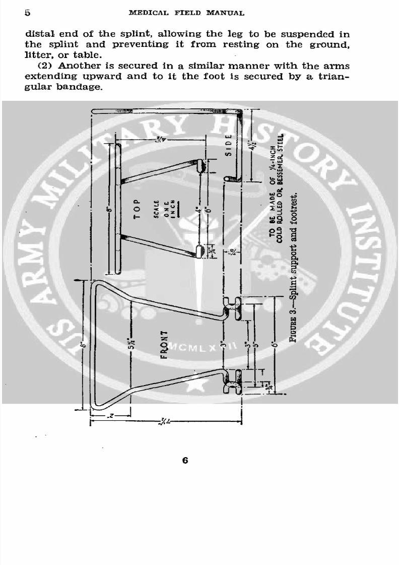
to obtain traction.* 5. SPLINT SUPPORT AND FOOTREST (fig. 3) .- Two of thesesupports are issued with each Army hinged half-ring splintfor field use.
4
8/7/2019 FM 8-50 1940
http://slidepdf.com/reader/full/fm-8-50-1940 9/94
SPLINTS, APPLIANCES, AND BANDAGES 5
a. Description.-They are made of Y/4 -inch cold rolled orBessemer steel rod. The efficiency of the appliance depends
upon its spring; therefore the rod should be worked cold, as
heat will remove the temper.
3- '3
CKSS ;FX
b. Uses (figs. 4 and 5) .- (1) One support is attached to the
lateral bars of the Army hinged half-ring splint with the
arms of the appliance toward the distal end of the splint
after the leg has been fixed in the splint. It supports the
8/7/2019 FM 8-50 1940
http://slidepdf.com/reader/full/fm-8-50-1940 10/94
5 MEDICAL FIELD MANUAL
distal end of the splint, allowing the leg to be suspended in
the splint and preventing it from resting on the ground,
litter, or table.
(2) Another is secured in a similar manner with the arms
extending upward and to it the foot is secured by a trian-gular bandage.
oa
6
8/7/2019 FM 8-50 1940
http://slidepdf.com/reader/full/fm-8-50-1940 11/94
SPLINTS, APPLIANCES, AND BANDAGES 5
/
2
;rl4
_ _ _~ ~ r~
8/7/2019 FM 8-50 1940
http://slidepdf.com/reader/full/fm-8-50-1940 12/94
5 MEDICAL rIELD MANUAL
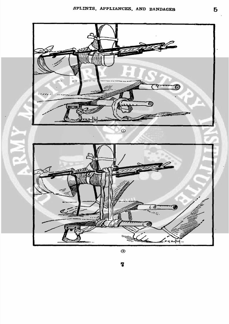
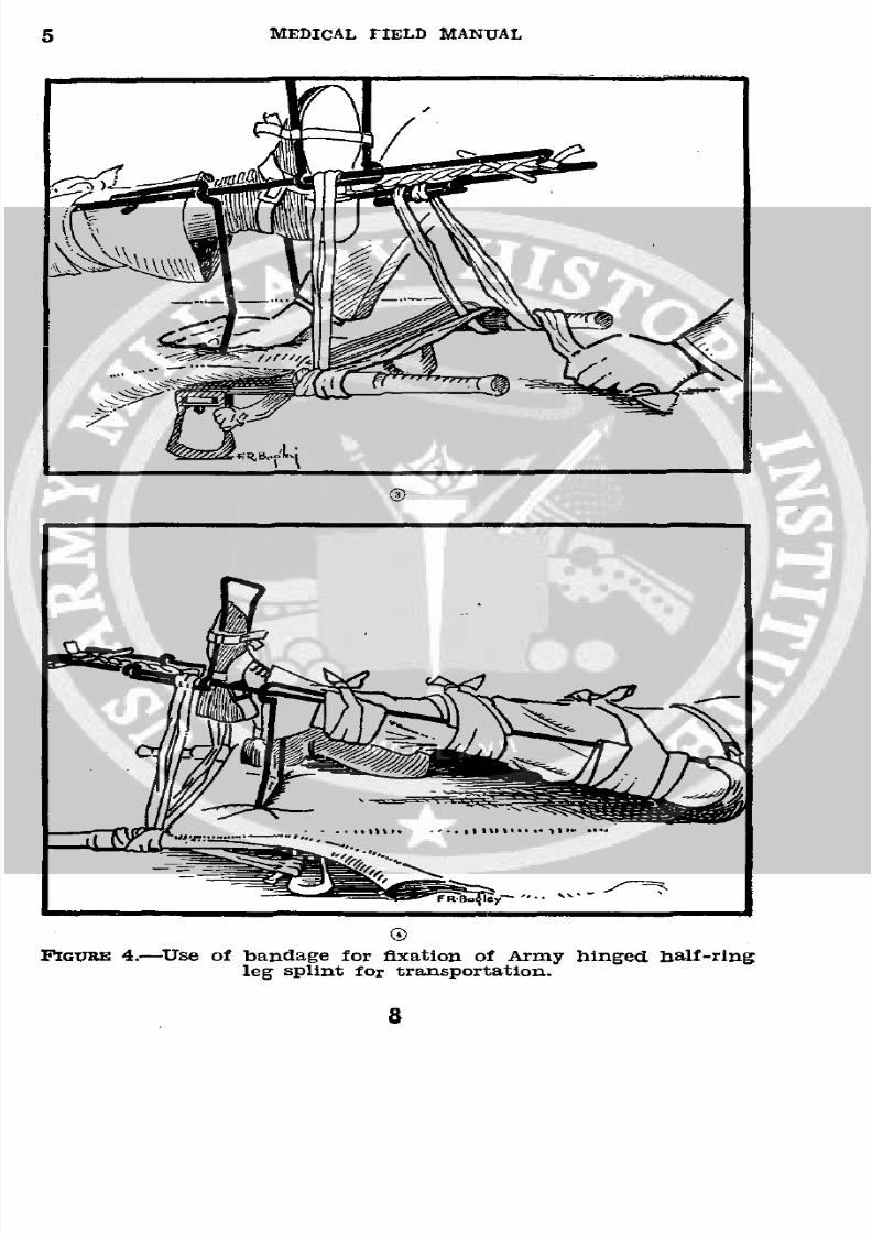
1oavE 4.-Use of bandage for fixation of Army hinged half-ring
leg splint for transportation.
8/7/2019 FM 8-50 1940
http://slidepdf.com/reader/full/fm-8-50-1940 13/94
SPLINTS, APPLIANCES, AND BANDAGES 5--43
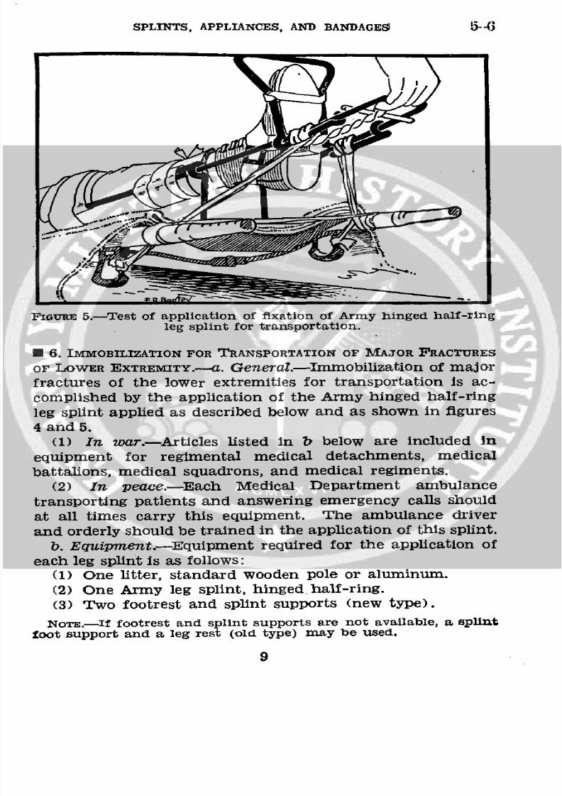
FIGuRE 5.-Test of application of fixation of Army hinged half-ring
leg splint for transportation.
* 6. IMMOBILIZATION FOR TRANSPORTATION OF MAJOR FRACTURES
OF LOWER EXTREMITY.-. General.-Immobilization of major
fractures of the lower extremities for transportation is ac-
complished by the application of the Army hinged half-ring
leg splint applied as described below and as shown in figures
4 and 5.
(1) In war.-Articles listed in b below are included inequipment for regimental medical detachments, medical
battalions, medical squadrons, and medical regiments.
(2) In peace.-Each Medical Department ambulance
transporting patients and answering emergency calls should
at all times carry this equipment. The ambulance driver
and orderly should be trained in the application of this splint.
b. Equipment.-Equipment required for the application ofeach leg splint is as follows:
(1) One litter, standard wooden pole or aluminum.
(2) One Army leg splint, hinged half-ring.
(3) Two footrest and splint supports (new type).
NoTE.--If footrest and splint supports are not available, a splint
toot support and a leg rest (old type) may be used.
9
8/7/2019 FM 8-50 1940
http://slidepdf.com/reader/full/fm-8-50-1940 14/94
6 IMEDICALFIELD MANUAL
(4) One traction strap (fig. 2).
(5) Two rolls of muslin bandage, 5 inches by 5 yards, and
one gauze bandage.
(6) Three blankets.
(7) Six safetypins.(8) One first-aid packet.
c. Application.-Two men, Privates A and B, work together
in the application of the traction fixation splints for trans-
portation, carrying out the following procedures:
(1) A grasps and makes traction on the foot of the patientwhile B applies the traction strap or ankle hitch over the
shoe.(2) While traction is continued by A, if the fracture is com-
pound, B cuts away clothing about the wound and applies
an occlusive dressing (first-aid packet).
(3) While traction is continued by A, B adjusts the Army
hinged half-ring splint (right or left), locking the half ring
at a right angle to the bars of the splint, sliding it from theoutside inward, the short rod to the inner side of the leg
and the half ring well up under the buttock against thetuberosity of the ischium. He then tightens the anterior
strap to hold it there.
(4) B secures the traction strap to the end of the splintand increases traction by the Spanish windlass method (figs.
4 () and 5), after which A gradually released his traction onthe foot.
(5) A attaches the splint support to the splint and ties thefoot in position against it, using available bandage or binding
material.
(6) B attaches the footrest to the splint with lower hooks
downward and inside the splint rods. The footrest is pushed
against the shoe to prevent foot drop. The footrest should
be spread, if necessary, for a more secure fit, and secured
with bandage to prevent lateral movement of the foot.
d. Fixationof Army hinged half-ring leg splint.-The splintis fixed to the litter in the following manner:
(1) Take a roll of the bias muslin bandage and stretch it
to its greatest length. (In emergency, any strong enough
binding material may be used.)
10
8/7/2019 FM 8-50 1940
http://slidepdf.com/reader/full/fm-8-50-1940 15/94
SPLINTS, APPLIANCES, AND BANDAGES 6
(2) Tie one end of bandage to lEtter stirrup on the side
of the fracture, placing knot near the pole. (See fig. 4 (D.)
The knot is placed on the stirrup near the pole and bandagewound around the bevel of the handle near edge of canvas to
keep bandage from slipping and becoming loose.(3) Keeping a constant tension on the bandage, carry it to
inside of bevel of the handle close to the canvas and wind itaround the handle twice. (See fig. 4 (.)
(4) Carry bandage to near side rod of leg splint, keeping
it at a 90°
angle (perpendicular) to the splint. Wind bandage
around splint rod twice and carry it back and around the
same handle of the litter. Then press splint firmly down onlitter and continue the constant pull on the bandage so thatall slack in the bandage going from the litter to the splint
and from the splint back to the litter will be taken up. (Seefig. 4 (.)
NoTE.-The bandage is kept under constant tension as it is ap-plied in order to overcome its elasticity. The small amount ofelasticity remaining is considered beneficial. In an emergency, wire,rope, or other binding material may be used for fastening the splint
to the handles of the litter.
(5) Carry bandage across the litter to bevel of opposite
handle and wind it around twice. (See fig. 4 (D and (.)(6) Secure side rod of splint on the other side just the same
as was done on the near side. Finish by tying the bandage
to the stirrup. (See fig. 4 ().)
(7) When the muslin bandage is properly applied and tied,
the splinted leg and end of litter can be lifted clear of theground without loosening the muslin bandage. The position
of the splint rest on the blanket and canvas remains un-
affected and the bandage is still taut when the end of thelitter is again lowered to the ground. (See fig. 5.)
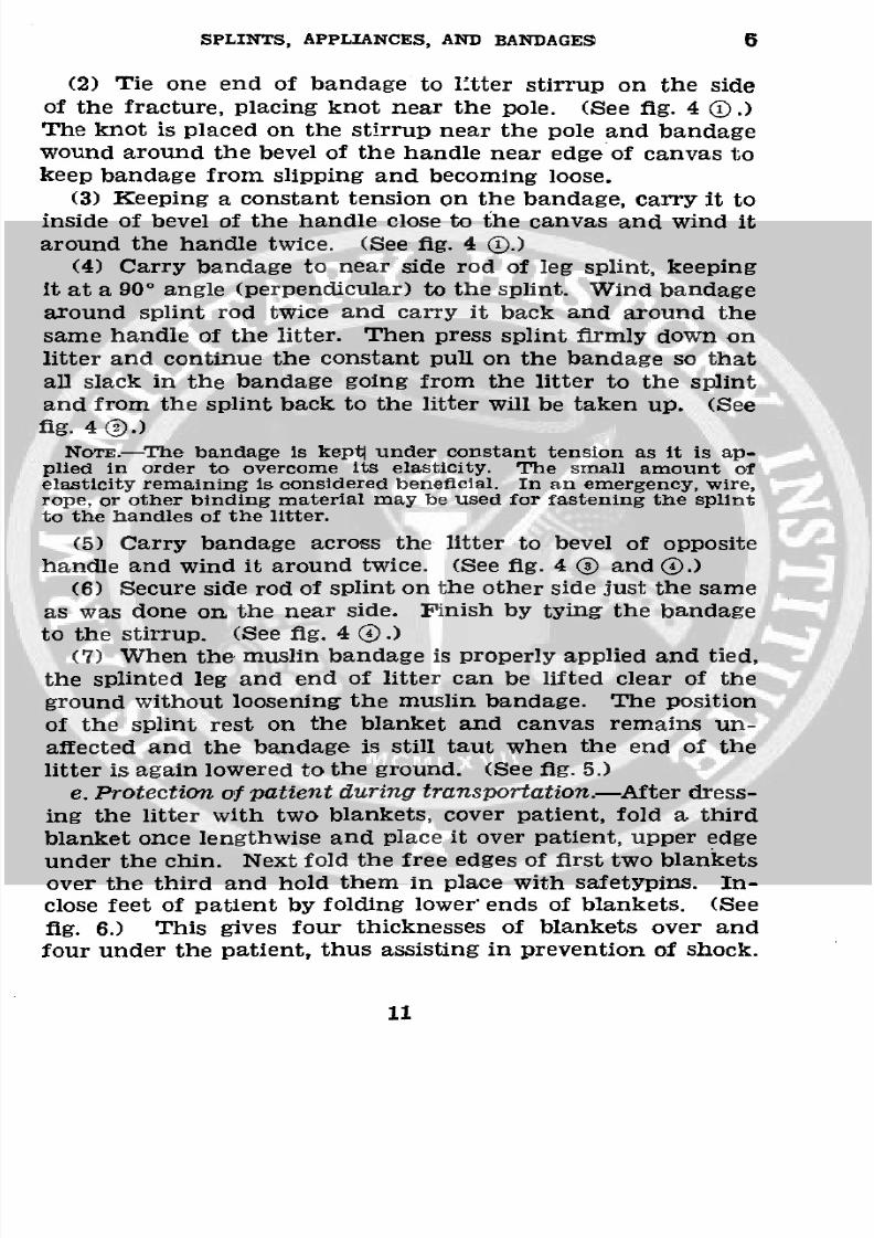
e. Protectionof patientduring transportation.-Afterdress-ing the litter with two blankets, cover patient, fold a third
blanket once lengthwise and place it over patient, upper edge
under the chin. Next fold the free edges of first two blanketsover the third and hold them in place with safetypins. In-close feet of patient by folding lower' ends of blankets. (See
fig. 6.) This gives four thicknesses of blankets over and
four under the patient, thus assisting in prevention of shock.
11
8/7/2019 FM 8-50 1940
http://slidepdf.com/reader/full/fm-8-50-1940 16/94
6-7 MEDICAL FIELD MANUAL
PIGURE 6.-Arrangement of blankets for transportation of patient
with Army leg splint applied.
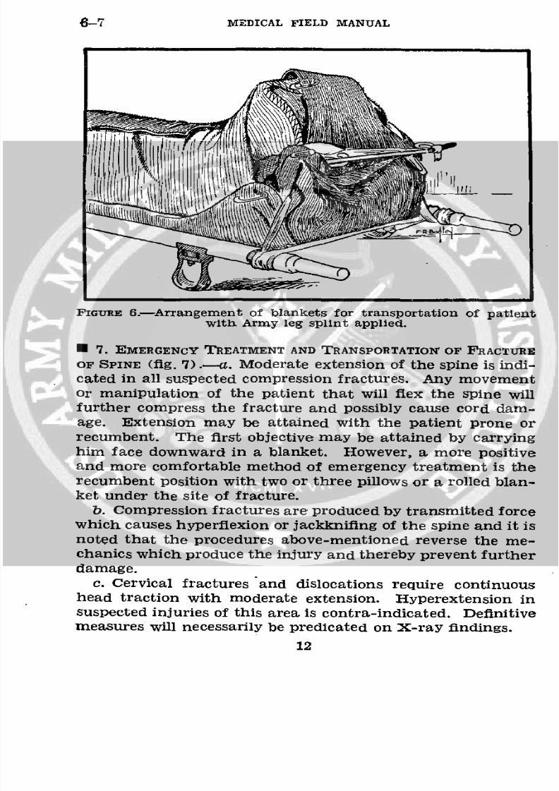
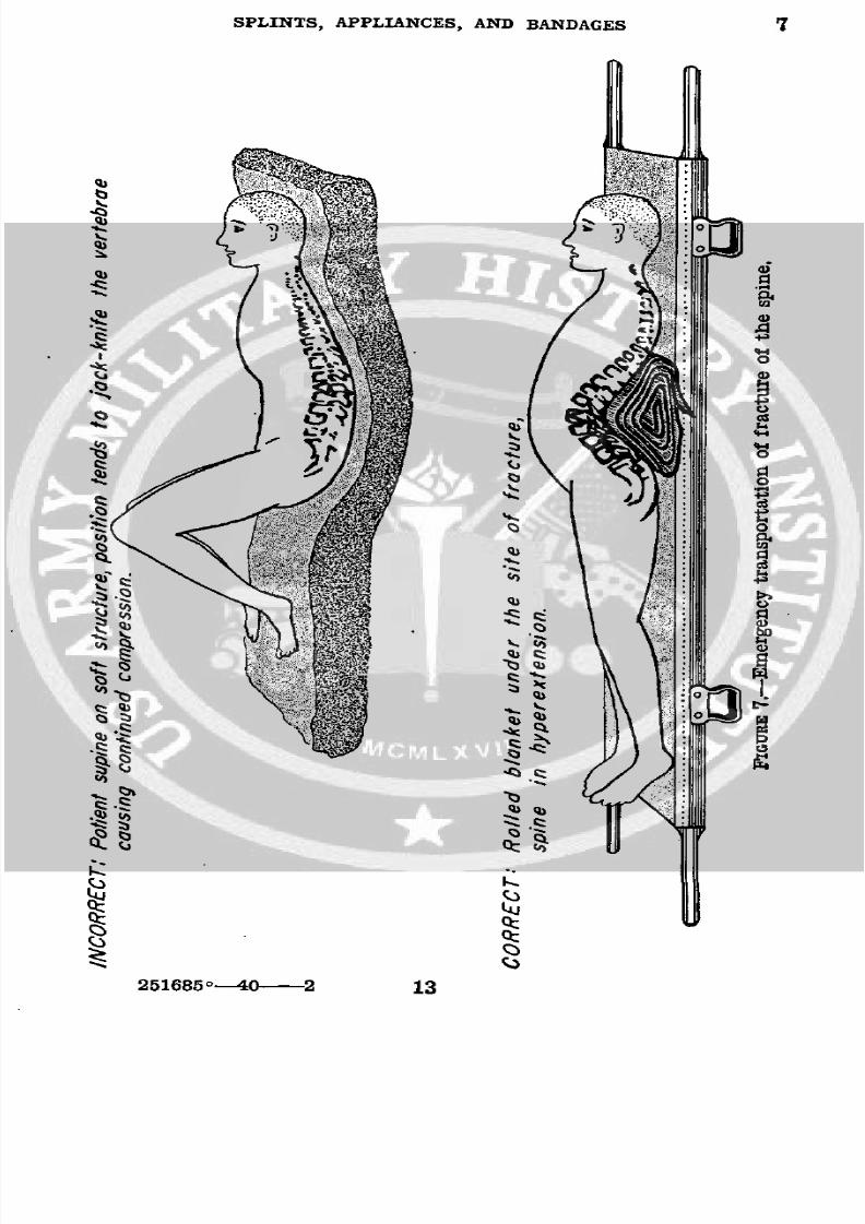
7. EMERGENCY TREATMENT AND TRANSPORTATION OF FRACTURE
OF SPINE (fig. 7).-a. Moderate extension of the spine is indi-cated in all suspected compression fractures. Any movementor manipulation of the patient that will flex the spine willfurther compress the fracture and possibly cause cord dam-age. Extension may be attained with the patient prone or
recumbent. The first objective may be attained by carryinghim face downward in a blanket. However, a more positiveand more comfortable method of emergency treatment is therecumbent position with two or three pillows or a rolled blan-ket under the site of fracture.
b. Compression fractures are produced by transmitted forcewhich causes hyperflexion or jackknifing of the spine and it isnoted that the procedures above-mentioned reverse the me-
chanics which produce the injury and thereby prevent furtherdamage.
c. Cervical fractures and dislocations require continuoushead traction with moderate extension. Hyperextension insuspected injuries of this area is contra-indicated. Definitivemeasures will necessarily be predicated on X-ray findings.
12
8/7/2019 FM 8-50 1940
http://slidepdf.com/reader/full/fm-8-50-1940 17/94
SPLINTS, APPLIANCES, AND BANDAGES
4;
S I 4
·,~~~~~~~~~~~~~~~~~~~4
g ~~~~ Co
cCZC
~~~~~~~~~~~~
-0Lu
251685°--40 2 13
9 ~~~~~~~~.
o a~~~~~~~~~~~~~
9,~~~~~~~~ I
Co ,
0,.$ 13
8/7/2019 FM 8-50 1940
http://slidepdf.com/reader/full/fm-8-50-1940 18/94
8 MEDICAL FIELD MANUAL
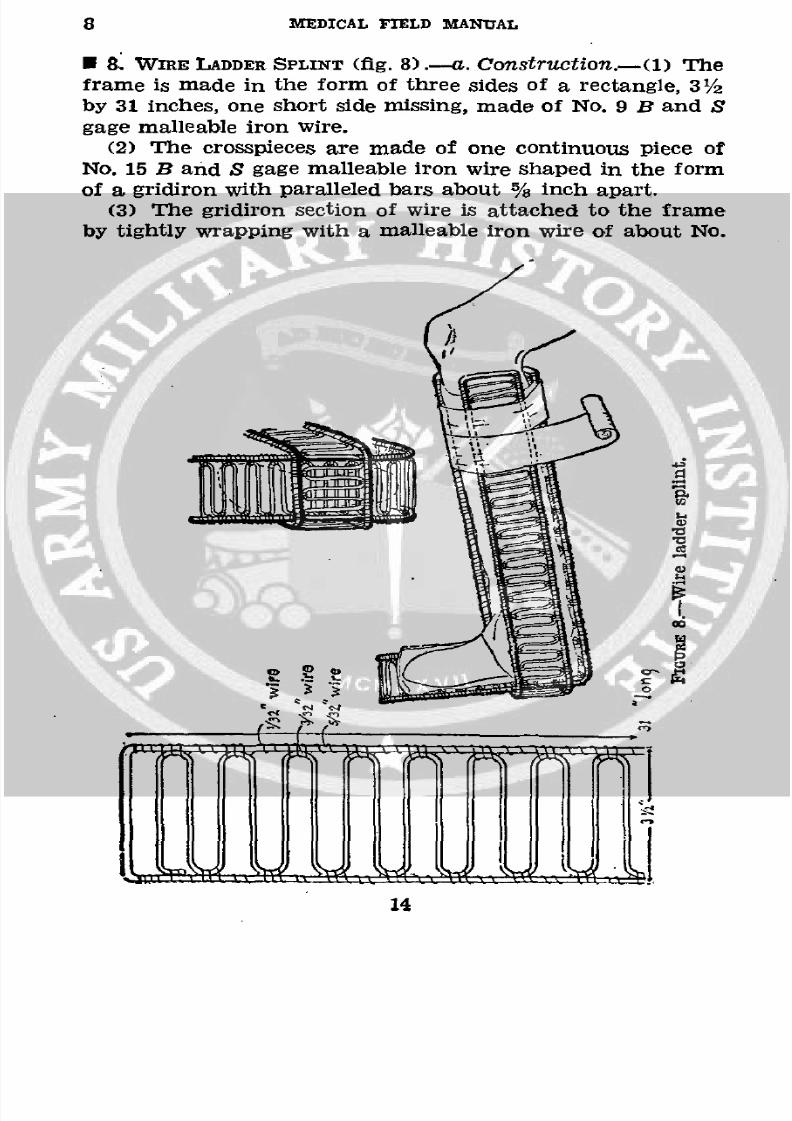
* 8. WIRE LADDER SPLINT (fig. 8).-a. Construction.-(1) The
frame is made in the form of three sides of a rectangle, 31/2
by 31 inches, one short side missing, made of No. 9 B and S
gage malleable iron wire.
(2) The crosspieces are made of one continuous piece ofNo. 15 B and S gage malleable iron wire shaped in the form
of a gridiron with paralleled bars about % inch apart.
(3) The gridiron section of wire is attached to the frame
by tightly wrapping with a malleable iron wire of about No.
eaSAP i
8/7/2019 FM 8-50 1940
http://slidepdf.com/reader/full/fm-8-50-1940 19/94
SPLINTS, APPLIANCES, AND BANDAGESI 8-9
22 B and S gage, three turns to each lateral section and two
in between. Ends are well wrapped and secured.
(4) Following assembly, the splint is heavily galvanized,
b. Uses.-(1) Splinting for transportation of Pott's frac-
tures, injuries, and fractures about the ankle and foot, gauzecotton pads in peacetime, and first-aid packet, large, in war
are used as padding. The splints, when padded and applied,
are held in position by a bias muslin bandage.
(2) As coaptation splints in the field or in hospital.
(3) Where a malleable light splint is required for a tem-
porary period, as for the shoulder, elbow, or wrist to maintain
afixed position other
thanthat of extension.
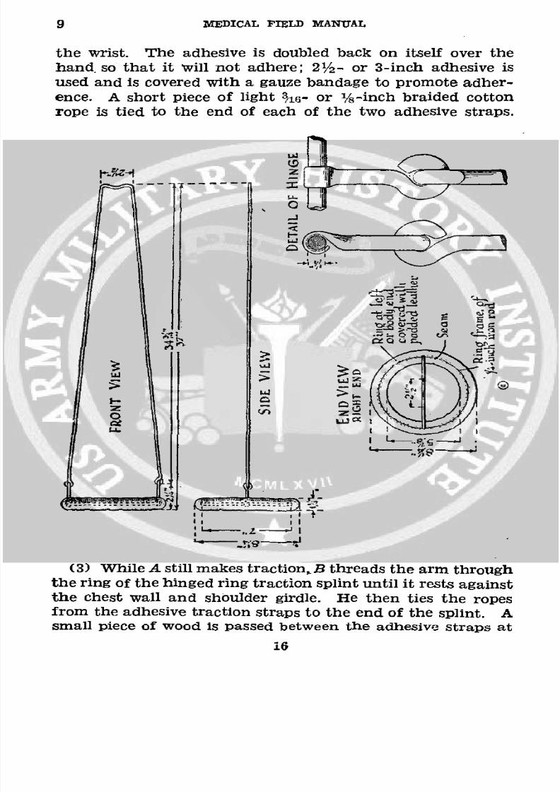
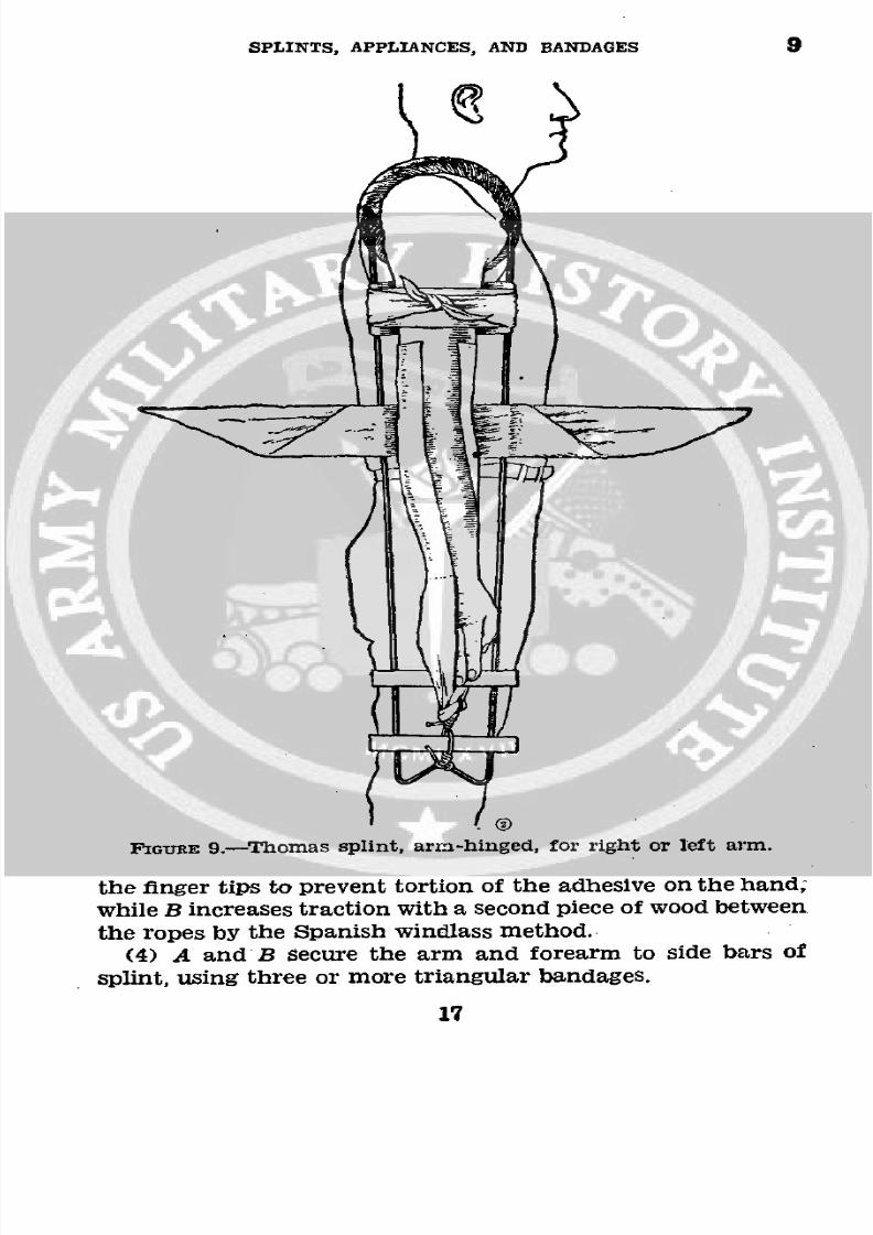
*9. THoMAS SPLINT, ARM-HINGED (fig. 9) .- a. Construction.-(1) This splint is made of ¼/4-inch cold rolled or Bessemer
steel rod, gray saddle felt, and three pieces of horsehide.
(2) The ring is protected with gray saddle felt covered with
first-cut horsehide, cream color, not oiled or dressed, and free
from material that might irritate the skin. The leather is
neatly and securely sewed with waxed linen thread, using a
baseball stitch (about four to the inch). The covering is sostitched that the surface coming in contact with the patient
is smooth. The finished padded portion is about 11/4 inches
in diameter.
(3) The splint with material for its application forms apart of the battalion, regimental medical detachment, and
medical regiment equipment. It should also be carried in
each ambulance.
b. Uses.-This splint is used in the treatment of injuries
to-
(1) Shoulder joints.
(2) Shaft of humerus.
(3) Elbow joint.
(4) Upper one-third of forearm.
*c. Application, upper extremity.-(1) A grasps the hand
and makes traction. Traction other than by hand shouldnot be used. B determines site of fracture. He removes all
clothing to shoulder, and if the fracture is compound, iodizes
the wound and applies an occlusive dressing.
(2) B applies adhesive plaster to the dorsal and volar sUr-
faces of the arm from the fracture point or above down. to
15
8/7/2019 FM 8-50 1940
http://slidepdf.com/reader/full/fm-8-50-1940 20/94
9 MEDICAL FIELD MANUAL
the wrist. The adhesive is doubled back on itself over the
hand so that it will not adhere; 21/2- or 3-inch adhesive isused and is covered with a gauze bandage to promote adher-ence. A short piece of light 316- or /8-inch braided cotton
rope is tied to the end of each of the two adhesive straps.
.]-
0 Z.
I' '
J I 1
, ,.Z
'-
I
(3) While A still makes traction.B threads the arm throughthe ring of the hinged ring traction splint until it rests against
the chest wall and shoulder girdle. He then ties the ropesfrom the adhesive traction straps to the end of the splint. Asmall piece of wood is passed between the adhesive straps at
i6
8/7/2019 FM 8-50 1940
http://slidepdf.com/reader/full/fm-8-50-1940 21/94
SPLINTS, APPLIANCES, AND BANDAGES 9
FIGURE 9,-Thomas splint, arm-hinged, for right or left arm.
the finger tips to prevent tortion of the adhesive on the hand;
while B increases traction with a second piece of wood between
the ropes by the Spanish windlass method.
(4) A and B secure the arm and forearm to side bars of
splint, using three or more triangular bandages.
17
8/7/2019 FM 8-50 1940
http://slidepdf.com/reader/full/fm-8-50-1940 22/94
10-11 MEDICAL FIELD MANUAL
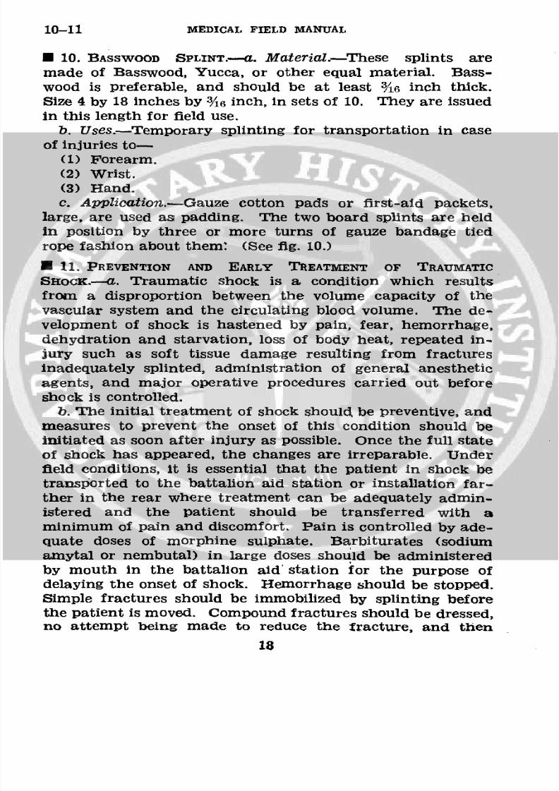
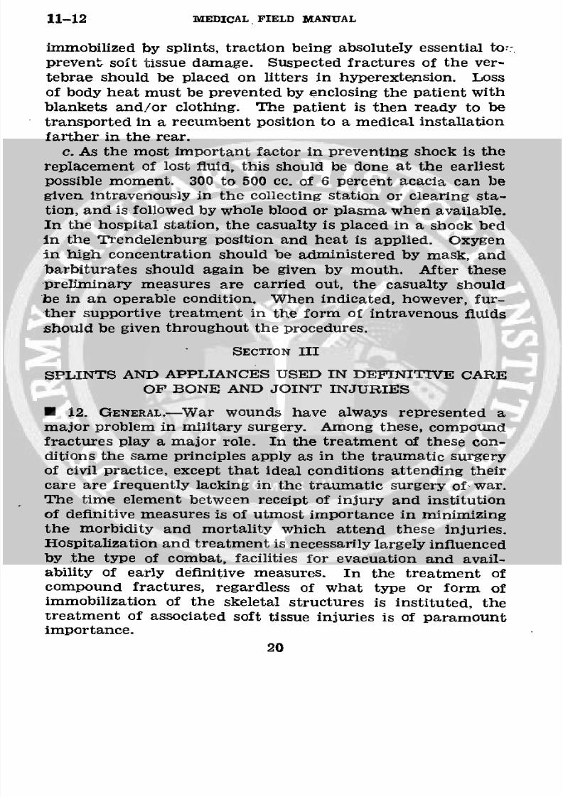
* 10. BASSWOOD SPLINT.-a. Material.-These splints are
made of Basswood, Yucca, or other equal material. Bass-wood is preferable, and should be at least 3A6 inch thick.
Size 4 by 18 inches by 3/16 inch, in sets of 10. They are issued
in this length for field use.
b. Uses.-Temporary splinting for transportation in case
of injuries to-(1) Forearm.
(2) Wrist.
(3) Hand.
c. Application.-Gauze cotton pads or first-aid packets,
large, are used as padding. The two board splints are heldin position by three or more turns of gauze bandage tied
rope fashion about them: (See fig. 10.)
* 11. PREVENTION AND EARLY TREATMENT OF TRAUMATIC
SHOCK.-a. Traumatic shock is a condition which resultsfrom a disproportion between the volume capacity of the
vascular system and the circulating blood volume. The de-
velopment of shock is hastened by pain, fear, hemorrhage,dehydration and starvation, loss of body heat, repeated in-
jury such as soft tissue damage resulting from fracturesinadequately splinted, administration of general anesthetic
agents, and major operative procedures carried out before
shock is controlled.
b. The initial treatment of shock should be preventive, andmeasures to prevent the onset of this condition should be
initiated as soon after injury as possible. Once the full stateof shock has appeared, the changes are irreparable. Under
field conditions, it is essential that the patient in shock be
transported to the battalion aid station or installation far-ther in the rear where treatment can be adequately admin-
istered and the patient should be transferred with a
minimum of pain and discomfort. Pain is controlled by ade-
quate doses of morphine sulphate. Barbiturates (sodium
amytal or nembutal) in large doses should be administeredby mouth in the battalion aid station for the purpose of
delaying the onset of shock. Hemorrhage should be stopped.
Simple fractures should be immobilized by splinting before
the patient is moved. Compound fractures should be dressed,no attempt being made to reduce the fracture, and then
18
8/7/2019 FM 8-50 1940
http://slidepdf.com/reader/full/fm-8-50-1940 23/94
SPLINTS, APPLIANCES, AND BANDAGES 11
NK si
FIGURE 10.-Temporary splinting of forearm, wrist, and hand fortransportation.
19
8/7/2019 FM 8-50 1940
http://slidepdf.com/reader/full/fm-8-50-1940 24/94
11-12 MEDICAL FIELD MANUAL
immobilized by splints, traction being absolutely essential tot:
prevent soft tissue damage. Suspected fractures of the ver-
tebrae should be placed on litters in hyperextension. Loss
of body heat must be prevented by enclosing the patient with
blankets and/or clothing. The patient is then ready to betransported in a recumbent position to a medical installation
farther in the rear.
c. As the most important factor in preventing shock is the
replacement of lost fluid, this should be done at the earliest
possible moment. 300 to 500 cc. of 6 percent acacia can begiven intravenously in the collecting station or clearing sta-tion, and is followed by whole blood or plasma when available.
In the hospital station, the casualty is placed in a shock bed
in the Trendelenburg position and heat is applied. Oxygen
in high concentration should be administered by mask, and
barbiturates should again be given by mouth. After thesepreliminary measures are carried out, the casualty should
be in an operable condition. When indicated, however, fur-ther supportive treatment in the form of intravenous fluids
should be given throughout the procedures.
SECTION III
SPLINTS AND APPLIANCES USED IN DEFINITIVE CAREOF BONE AND JOINT INJURIES
* 12. GENERAL.-War wounds have always represented amajor problem in military surgery. Among these, compound
fractures play a major role. In the treatment of these con-ditions the same principles apply as in the traumatic surgeryof civil practice, except that ideal conditions attending their
care are frequently lacking in the traumatic surgery of· war.The time element between receipt of injury and institutionof definitive measures is of utmost importance in minimizing
the morbidity and mortality which attend these injuries.Hospitalization and treatment is necessarily largely influenced
by the type of combat, facilities for evacuation and avail-ability of early definitive measures. In the treatment of
compound fractures, regardless of what type or form ofimmobilization of the skeletal structures is instituted, thetreatment of associated soft tissue injuries is of paramountimportance.
20
8/7/2019 FM 8-50 1940
http://slidepdf.com/reader/full/fm-8-50-1940 25/94
SPLINTS, APPLIANCES, AND BANDAGES 12-13
The treatment of compound fractures has two objectives:
To avoid or control infection, and to restore as accurately as
possible alinement and contact of the fragments and so main-
tain them throughout the process of repair. Debridement or
cleansing of the wound meets the first requirement. Thismeans excision of all damaged tissues particularly those de-
prived of circulation, the removal of extraneous material and
the thorough flushing of the wound with a nonirritating solu-
tion (normal saline). It should be emphasized that the use
of strong antiseptics in the wound, either at the time of first
aid treatment or during subsequent debridement, is not in
accord with present practice and is to be avoided. Chemo-
therapy in the form of sulfanilamide instilled either directly
in the wound or administered orally, or both, is being used
experimentally in compound fractures and may prove to be
an agent of value. The second, requirement, reduction andimmobilization of the fracture, may be attained by the appli-
cation of one of the various accepted methods.
* 13. DEFINITIVE TREATMENT OF FRACTURES.-The comments
given in this section are intended to be informative only andare not to be considered a detailed treatise on fracturetherapy.
a. Closed reduction.-Under anesthesia (general, spinal,
local, or intravenous) the fracture is reduced by manipula-
tion after the muscle, relaxed by anesthesia, has been com-
pletely "paralyzed" by traction. The reduction is maintained
by the use of splints or plaster of paris.b. Suspension and traction.-The fractured extremity is
suspended on a splint or appliance and reduction is accom-
plished by prolonged traction by means of the weight and
pulley method. The proximal fragment being fixed by themuscles inserted into it, the distal fragment is pulled in its
prolongation and so alined. Length, alinement, and contact
are the goal. Overpull of the fragments must be avoided.
c. Open reduction.-The fracture site is opened and reduc-tion accomplished under direct vision. To maintain reduc-
tion, some type of internal fixation is generally used, such as
steel or vitallium plates and screws, nails, bands, etc., and
this is ordinarily reinforced by some type of external fixation,
as splints or plaster of paris.
21
8/7/2019 FM 8-50 1940
http://slidepdf.com/reader/full/fm-8-50-1940 26/94
14 MEDICAL FIELD MANUAL
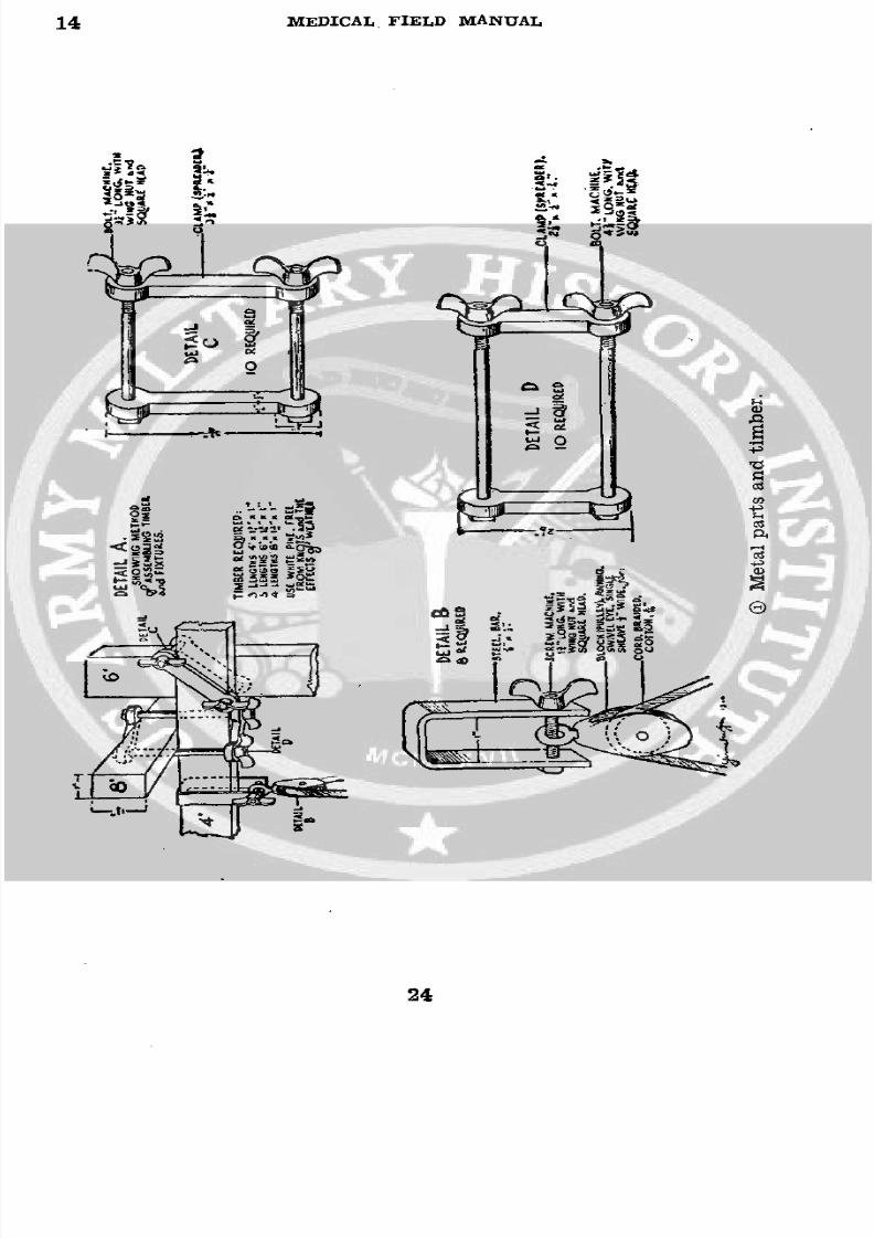
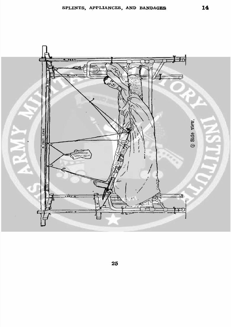
* 14. BALKAN FRAME (fig. 11) .- a. Material.
Bag buckshot, 3-inch (holds 1 pound) ---_______--___- __ 10
Bag buckshot, 5-inch (holds 5 pounds) _________--______ 10Bag buckshot, 8-inch (holds necessary number of 1- and
5-pound shot bags) -------------------------------- 5Buckshot, coarse----------------------------- pounds__ 50
Clamp, large (detail C, fig. 11 (0))----------.---- ____. 10Clamp, small (detail D, fig. 11 0) --- ___-______-- _______ 10Hammock for suspension of pelvis, large --____________ 1
Hammock, small (fig. 11 0) -------------------------__ 1Poles (detail A, fig. 11 0) ------------------------- set__ 1
4 feet by 13/4 by 1 inch -___--_---_______ --______- 3
6 feet by 13/4 by 1 inch------------.------------ __ 58 feet by 13/4 by 1 inch -______---_________________ 4
Pulley assemblage (detail B, fig. 11 (0)) _--____---- _______ 8Rope,
3/16 -inch, braided cotton (unglazed) __-----yards--__ 30
. b. Uses.-Forsuspension of upper extremity, lower extrem-
ity, fractures of the pelvis, or the whole body when in plaster.
c. Application.-(1) The middle overhead pole of the frame
from which the leg is suspended is placed parallel with thelong axis of the leg. Sufficient weight (1- and 5-pound shot
bags) is placed in the open-mouthed bag to balance theweight of the splint and leg. The rope going over the pulley
at the head of the bed carries sufficient weight (about 8
pounds) to hold the ring of the splint in position against theIschial tuberosity. Traction is obtained by means of weights
(25 to 30 pounds) through adhesive skin traction, ropes, and
pulley. (See fig. 11 ( and 0.)(2) The extremity is suspended in the splint by the use
of canton flannel (5-inch) bandages as slings, using large
safetypins for fixation.
(3) Length is obtained by weight and pulley traction.
Alinement is obtained by abduction, adduction, flexion, or
extension of the distal end of the distal fragment. Alinement
is also changed by adjusting the position and tightness of thesupporting canton flannel slings.
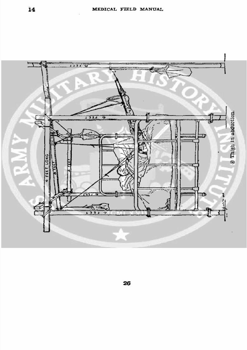
(4) Figure 11 O and® shows an intertrochanteric frac-
ture of the femur treated in extreme abduction, using skin
traction.
22
8/7/2019 FM 8-50 1940
http://slidepdf.com/reader/full/fm-8-50-1940 27/94
SPLINTS, APPLIANCES, AND BANDAGES 14
(5) The frame allows any position of abduction or adduc-
tion. All four extremities or any combination may be sus-
pended at one time.
(6) The foot of the bed is ordinarily elevated so that thebody will better act as a counterweight against traction.
(7) If there is a wound in the region of the ischial tuber-
osity, the half ring of the splint may be reversed to theanterior surface of the thigh and dressings held in place
behind by the strap and buckle.
(8) A "monkey bar" made of a broomstick and suspended
from the frame by rope so that it hangs within reach of the
patient is a welcome aid to him in changing his position in
bed.d. Fractureof humerus treated by skin traction in abduc-
tion (fig. 11 (i) ).-(1) The humerus is suspended in a can-
vas hammock 8 by 30 inches, with ends of canvas-covered
wood in whichl four eyelets are placed. Laces are passed
through these eyelets as shown in figure 11 0.(2) The forearm and hand are suspended from a wooden
spreader, made locally, using four 1-inch steel buckles andsufficient 1-inch nonelastic webbing.
(3) A piece of broomstick makes an excellent handhold.
(4) Position of the distal fragment is changed by abduct-
ing or adducting the arm and likewise by changing the sup-
porting pole of the suspending frame and by increasing or
decreasing the weight attached to the forearm or that at-
tached to the hammock.
23
8/7/2019 FM 8-50 1940
http://slidepdf.com/reader/full/fm-8-50-1940 28/94
14 MEDICAL FIELD MANUAL
· j:
8/7/2019 FM 8-50 1940
http://slidepdf.com/reader/full/fm-8-50-1940 29/94
SPLINTS, APPLIANCES, AND BANDAGES 14
25U
25
8/7/2019 FM 8-50 1940
http://slidepdf.com/reader/full/fm-8-50-1940 30/94
14 MEDICAL FIELD MANUAL
iiJ91 .9i j
26
8/7/2019 FM 8-50 1940
http://slidepdf.com/reader/full/fm-8-50-1940 31/94
SPLINTS, APPLIANCES, AND BANDAGES 15
4 E T LONG
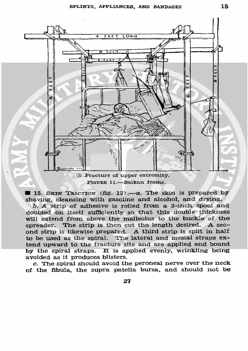
0 Fracture of upper extremity.
FIGURE 11.-Balkan frame.
* 15. SKIN TRACTION (fig. 12).-a. The skin is prepared byshaving, cleansing with gasoline and alcohol, and drying.
b. A strip of adhesive is rolled from a 3-inch spool and
doubled on itself sufficiently so that this double thickness
will extend from above the malleolus to the buckle of thel
spreader. The strip is then cut the length desired. A sec-
ond strip is likewise prepared. A third strip is split in half
to beused as the spiral. The lateral and mesial straps ex-
tend upward to the fracture site and are applied and bound
by the spiral straps. It is applied evenly, wrinkling being
avoided as it produces blisters.
c. The spiral should avoid the peroneal nerve over the neck
of the fibula, the supra patella bursa, and should not be
27
8/7/2019 FM 8-50 1940
http://slidepdf.com/reader/full/fm-8-50-1940 32/94
15 MEDICAL FIELD MANUAL
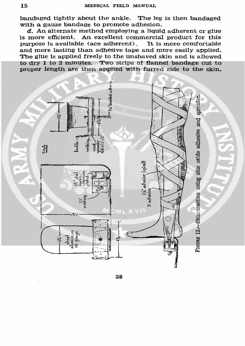
bandaged tightly about the ankle. The leg is then bandaged
with a gauze bandage to promote adhesion.
d. An alternate method employing a liquid adherent or glue
is more efficient. An excellent commercial product for this
purpose is available (ace adherent). It is more comfortable
and more lasting than adhesive tape and more easily applied.
The glue is applied freely to the unshaved skin and is allowed
to dry 1 to 2 minutes. Two strips of flannel bandage cut toproper length are then applied with furred side to the skin.
_.-1
28
8/7/2019 FM 8-50 1940
http://slidepdf.com/reader/full/fm-8-50-1940 33/94
SPLINTS, APPLIANCES, AND BANDAGES 15-17
The extremity is snugly wrapped with biased muslin bandage.
Traction may be applied immediately.
e. For below-knee traction, the adhesive extends only to
the knee. The spreader and foot support are made locally
from sheet aluminum; webbing 11/2 inch, gray, nonelastic;buckle 11/2 inch, two-prong; wood 4% by 11/2 by 1/2 inch pine;
tacks, rivets, or screws.
HANDLE FOR INS Gr& YOF PINS
00o
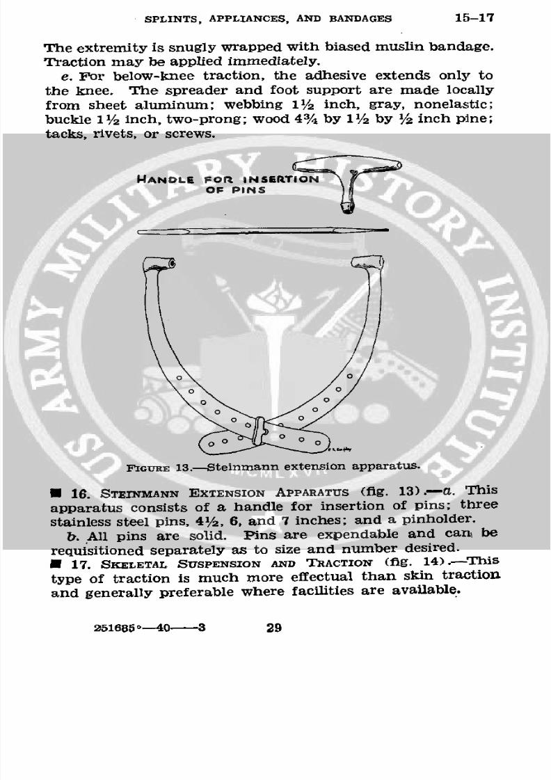
FIGURE 13.-Steinmann extension apparatus.
* 16. STEINMANN EXTENSION APPARATUS (fig. 13).--a. This
apparatus consists of a handle for insertion of pins; three
stainless steel pins, 41/2, 6, and 7 inches; and a pinholder.
b. All pins are solid. Pins are expendable and can, berequisitioned separately as to size and number desired.
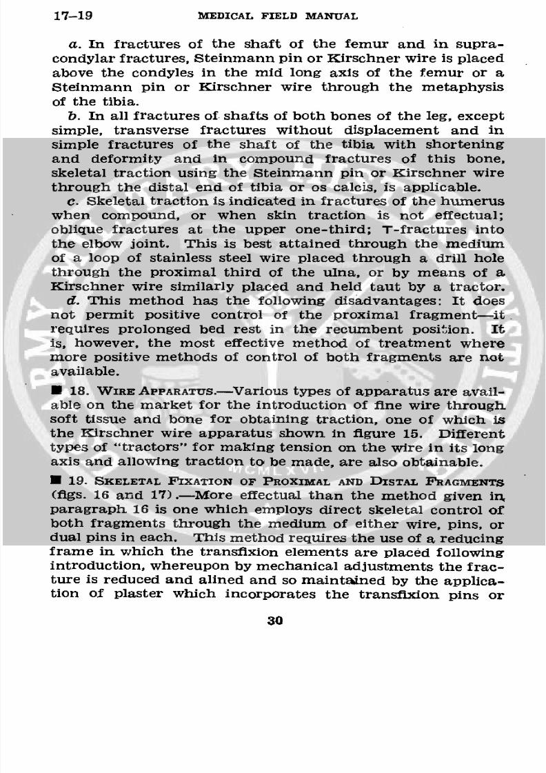
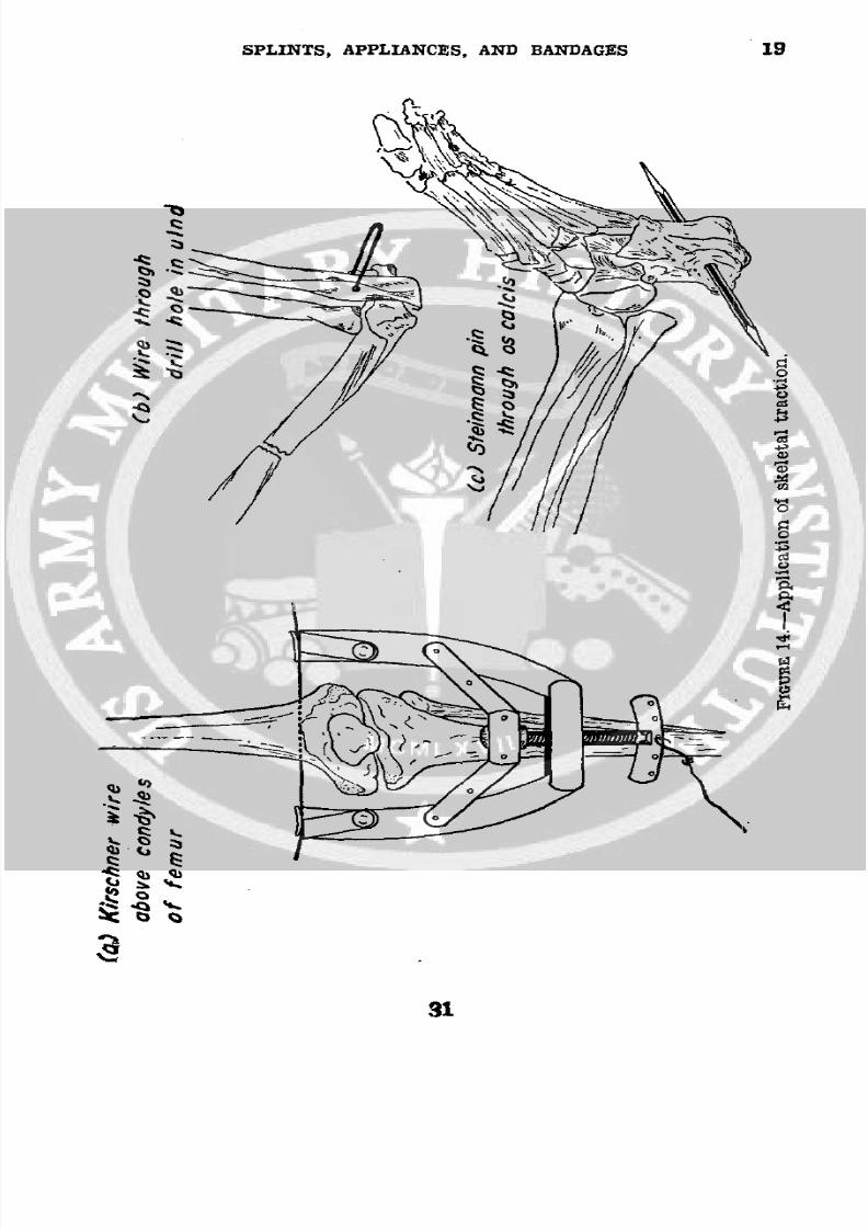
* 17. SKELETAL SUSPENSION AND TRACTION (fig. 14).--This
type of traction is much more effectual than skin traction
and generally preferable where facilities are available.
251685-- 40 3 29
8/7/2019 FM 8-50 1940
http://slidepdf.com/reader/full/fm-8-50-1940 34/94
17-19 MEDICAL FIELD MANUAL
a. In fractures of the shaft of the femur and in supra-
condylar fractures, Steinmann pin or Kirschner wire is placed
above the condyles in the mid long axis of the femur or a
Steinmann pin or Kirschner wire through the metaphysis
of the tibia.b. In all fractures of shafts of both bones of the leg, except
simple, transverse fractures without displacement and insimple fractures of the shaft of the tibia with shortening
and deformity and in compound fractures of this bone,
skeletal traction using the Steinmann pin or Kirschner wire
through the distal end of tibia or os calcis, is applicable.
c. Skeletal traction is indicated in fractures of the humerus
when compound, or when skin traction is not effectual;
oblique fractures at the upper one-third; T-fractures into
the elbow joint. This is best attained through the medium
of a loop of stainless steel wire placed through a drill hole
through the proximal third of the ulna, or by means of a
Kirschner wire similarly placed and held taut by a tractor.d. This method has the following disadvantages: It does
not permit positive control of the proximal fragment-it.requires prolonged bed rest in the recumbent position. Itis, however, the most effective method of treatment wheremore positive methods of control of both fragments are not
available.
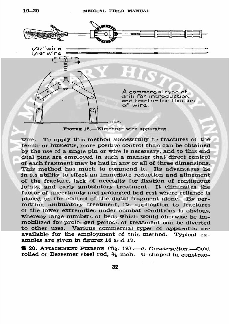
* 18. WIRE APPARATUS.-Various types of apparatus are avail-
able on the market for the introduction of fine wire through
soft tissue and bone for obtaining traction, one of which isthe Kirschner wire apparatus shown in figure 15. Different
types of "tractors" for making tension on the wire in its long
axis and allowing traction to be made, are also obtainable.
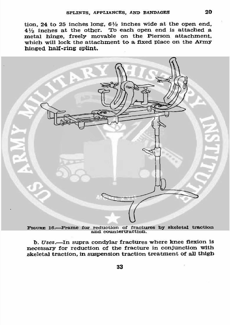
* 19. SKELETAL FIXATION OF PROXIMAL AND DISTAL FRAGMENTS
(figs. 16 and 17).-More effectual than the method given in,
paragraph 16 is one which employs direct skeletal control of
both fragments through the medium of either wire, pins, ordual pins in each. This method requires the use of a reducingframe in which the transfixion elements are placed following
introduction, whereupon by mechanical adjustments the frac-ture is reduced and alined and so maintained by the applica-tion of plaster which incorporates the transfixion pins or
30
8/7/2019 FM 8-50 1940
http://slidepdf.com/reader/full/fm-8-50-1940 35/94
SPLINTS, APPLIANCES, AND BANDAGES 19
QiQ
Ret tA'//////
,c
0. 4 .
4 3
8/7/2019 FM 8-50 1940
http://slidepdf.com/reader/full/fm-8-50-1940 36/94
19-20 MEDICAL FIELD MANUAL
,/32"wire -
/.IG" wire.
A commercial type, oFdrill For introductioNand tractor For Fixationof wire.
FIGURE 15.-Kirschner wire apparatus.
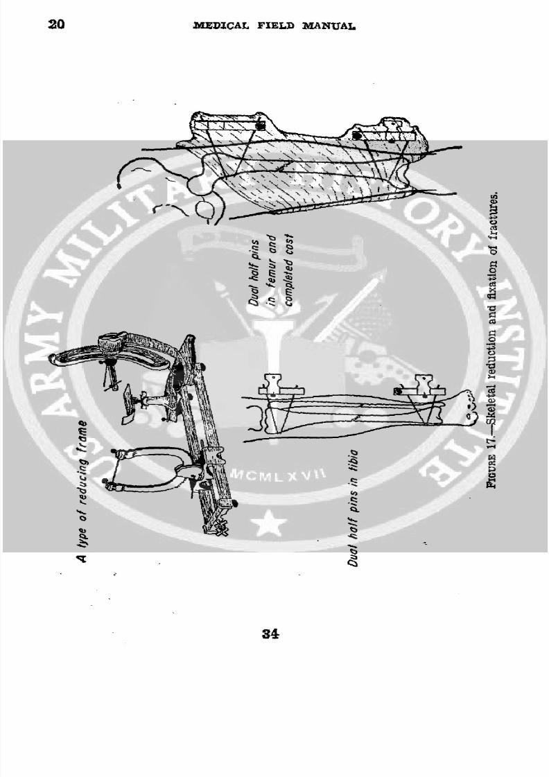
wire. To apply this method successfully to fractures of the
femur or humerus, more positive control than can be obtained
by the use of a single pin or wire is necessary, and to this enddual pins are employed in such a manner that direct control
of each fragment may be had in any or all of three dimensions.
This method has much to commend it. Its advantages lie
in its ability to effect an immediate reduction and alinement
of the fracture, lack of necessity for fixation of contiguousjoints, and early ambulatory treatment. It eliminates thefactor of uncertainty and prolonged bed rest where reliance is
placed on the control of the distal fragment alone. By per-mitting ambulatory treatment, its application to fractures
of the lower extremities under combat conditions is obvious,whereby large numbers of beds which would oherwise be im-
mobilized for prolonged periods of treatment can be divertedto other uses. Various commercial types of apparatus areavailable for the employment of this method. Typical ex-
amples are given in figures 16 and 17.
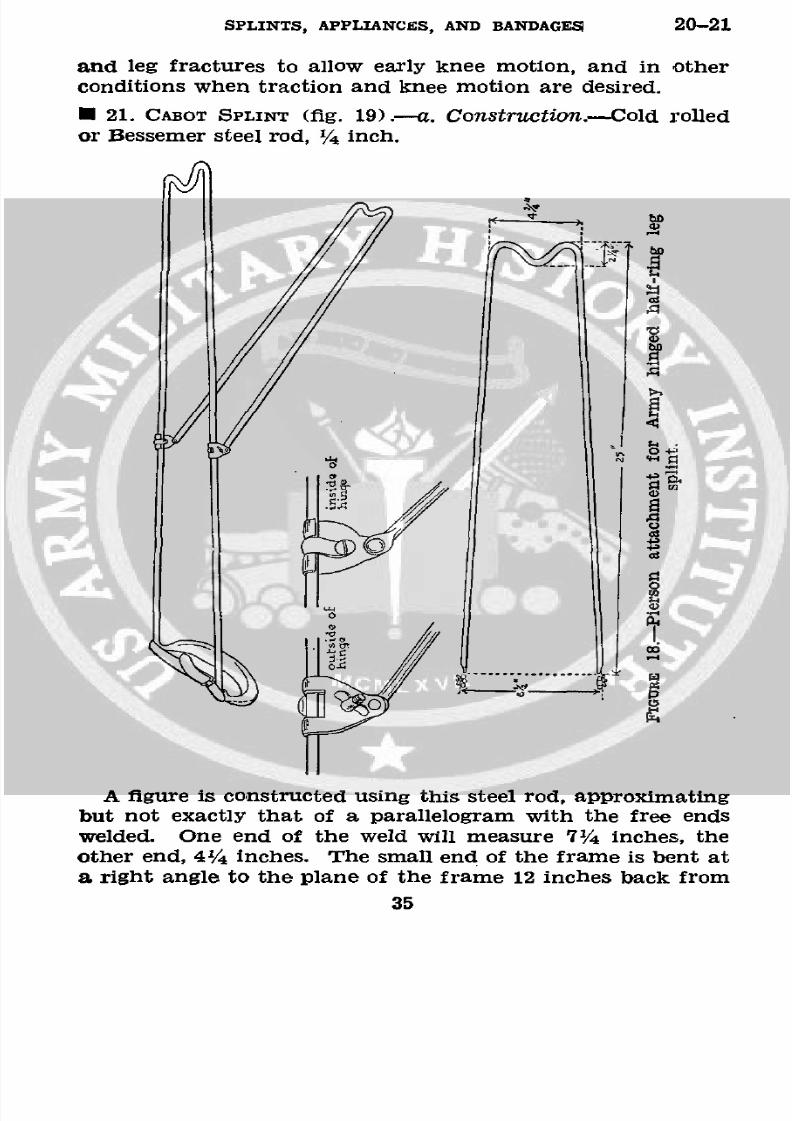
* 20. ATTACHMENT PIERSON (fig. 18).-a. Construction.-Cold
rolled or Bessemer steel rod, 3/8 inch. U-shaped in construe-
32
8/7/2019 FM 8-50 1940
http://slidepdf.com/reader/full/fm-8-50-1940 37/94
SPLINTS, APPLIANCES, AND BANDAGES 20
tion, 24 to 25 inches long, 61/2 inches wide at the open end,
41/2 inches at the other. To each open end is attached ametal hinge, freely movable on the Pierson attachment,
which will lock the attachment to a fixed place onthe
Armyhinged half-ring splint,
IGURE 16.--Frame for reduction of fractures by skeletal tractionand countertraction.
b. Uses.-In supra condylar fractures where knee flexion is
necessary for reduction of the fracture in conjunction withskeletal traction, in suspension traction treatment of all thigh
33
8/7/2019 FM 8-50 1940
http://slidepdf.com/reader/full/fm-8-50-1940 38/94
20 XMEDICAL FIELD MANUAL
QI
ah
8/7/2019 FM 8-50 1940
http://slidepdf.com/reader/full/fm-8-50-1940 39/94
SPLINTS, APPLIANCES, AND BANDAGES 20-21
and leg fractures to allow early knee motion, and in otherconditions when traction and knee motion are desired.
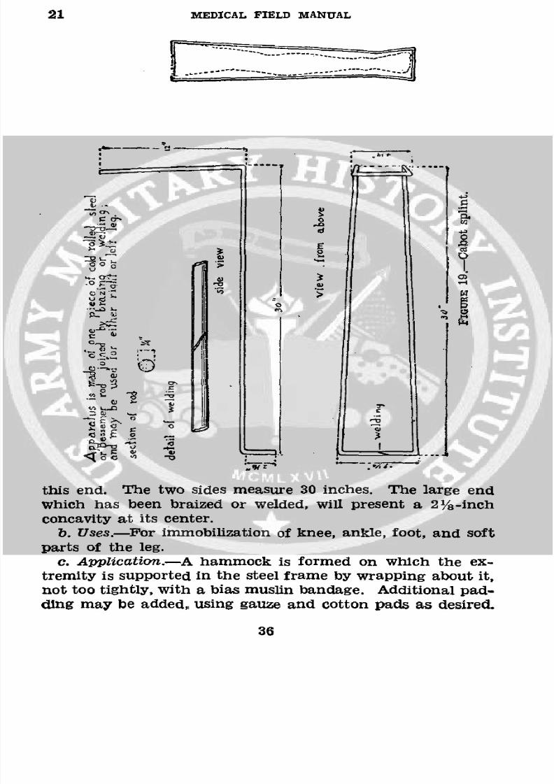
* 21. CABOT SPLINT (fig. 19).-a. Construction.-Cold rolled
or Bessemer steel rod, 1/4 inch.
'O.~.
other end, 41/4 inches. The small end of the frame is bent ata right angle to the plane of the frame 12 inches back from
35
8/7/2019 FM 8-50 1940
http://slidepdf.com/reader/full/fm-8-50-1940 40/94
21 MEDICAL FIELD MANUAL
° 0
which has been bralzed or welded, will present a 2/8-inch
parts of the leg.
o -'
c. Application.-A hammock is formed on which the ex-
tremity is supported in the steel frame by wrapping about it,not too tightly, with a bias muslin bandage. Additional pad-
cling may be added,, using gauze and cotton pads as desired.
36
ths ndTetw sde maur 3 ichs T e are n
8/7/2019 FM 8-50 1940
http://slidepdf.com/reader/full/fm-8-50-1940 41/94
SPLINTS, APPLIANCES, AND BANDAGES 21-22
The extremity should at no place rest on the metal bars of
the splint. The' splint may be bent at the knee to give any
amount of flexion desired. The extremity is bound to thesplint, using additional muslin bandages.
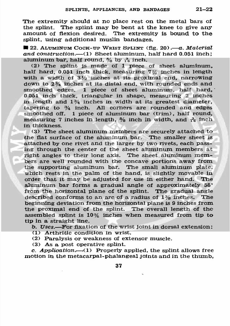
U 22. ALUMINUM COCK-UP WRIST SPLINT (fig. 20).-a. Material
and construction.-(1) Sheet aluminum, half hard 0.051 inch;aluminum bar, half round, % by -& nch.
(2) The splint is made of 1 piece of sheet aluminum,
half hard, 0.051 inch thick, measuring 73% inches in length
with a width of 31/2 inches at its proximal end, narrowing
down to 23/4 inches at its distal end, with rounded ends and
smoothed edges. 1 piece of sheet aluminum, half hard,'0.051 inch thick, triangular in shape, measuring 2 inches
in length and 13/4 inches in width at its greatest diameter,
tapering to 3/4 inch. All corners are rounded and edgessmoothed off. 1 piece of aluminum bar (trim), half round,
measuring 7 inches in length, % inch in width, and 136 inch
in thickness.
(3) The sheet aluminum members are securely attached to
the flat surface of the aluminum bar. The smaller sheet is
attached by one rivet and the larger by two rivets, each pass-
ing through the center of the sheet aluminum members atright angles to their long axis. The sheet aluminum mem-
bers are well rounded with the concave portions away from
the supporting aluminum bar. The small aluminum plate,
which rests in the palm of the hand, is slightly movable in
order that it may be adjusted for use in either hand. Thealuminum bar forms a gradual angle of approximately 58'
from the horizontal plane of the splint. The gradual angle
described conforms to an arc of a radius of 13/%inches. Thebeginning deviation from the horizontal plane is 9 inches from
the proximal end of the splint. The overall length of theassembled splint is 103/%inches when measured from tip totip in a straight line.
b. Uses.-For fixation of the wrist joint in dorsal extension:
(1) Arthritic condition in wrist.
(2) Paralysis or weakness of extensor muscle.
(3) As a post operative splint.
c. Application.(1) Properly applied, the splint allows freemotion in the metacarpal-phalangeal joints and in the thumb,
37
8/7/2019 FM 8-50 1940
http://slidepdf.com/reader/full/fm-8-50-1940 42/94
22-23 MEDICAL FIELD MANUAL
that is, no pressure on thenar eminence to produce "flat
hand."
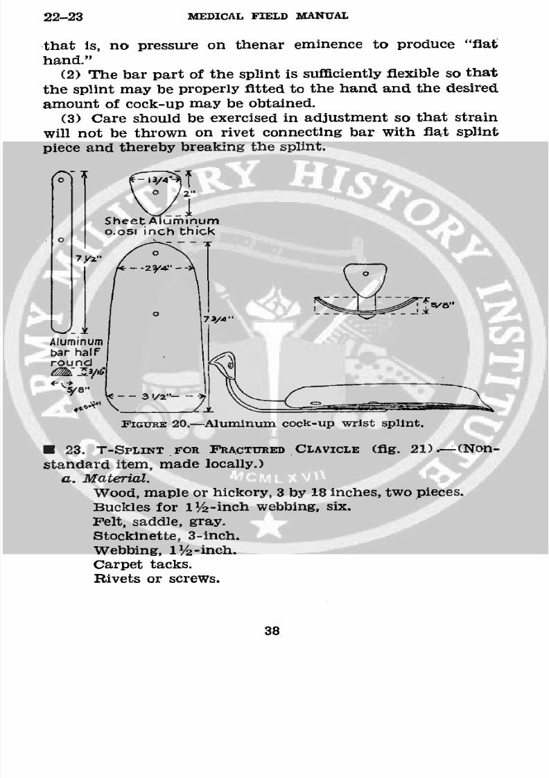
(2) The bar part of the splint is sufficiently flexible so that
the splint may be properly fitted to the hand and the desired
amount of cock-up may be obtained.(3) Care should be exercised in adjustment so that strain
will not be thrown on rivet connecting bar with flat splint
piece and thereby breaking the splint.
SheetAl inumo.osl inch thick
0
o7Y~"-2 -T i73/4"
Aluminumbar halfround
8' 20.-Aluminum cock-up wrist splint.
FIGURE 20.-Aluminum cock-up wrist splint.
* 23. T-SPLINT FOR FRACTURED CLAVICLE (fig. 21).-(Non-
standard item, made locally.)
a. Material.
Wood, maple or hickory, 3 by 18 inches, two pieces.
Buckles for 1/2-inch webbing, six.
Felt, saddle, gray.
Stockinette, 3-inch.Webbing, 1 /2 -inch.
Carpet tacks.
Rivets or screws.
38
8/7/2019 FM 8-50 1940
http://slidepdf.com/reader/full/fm-8-50-1940 43/94
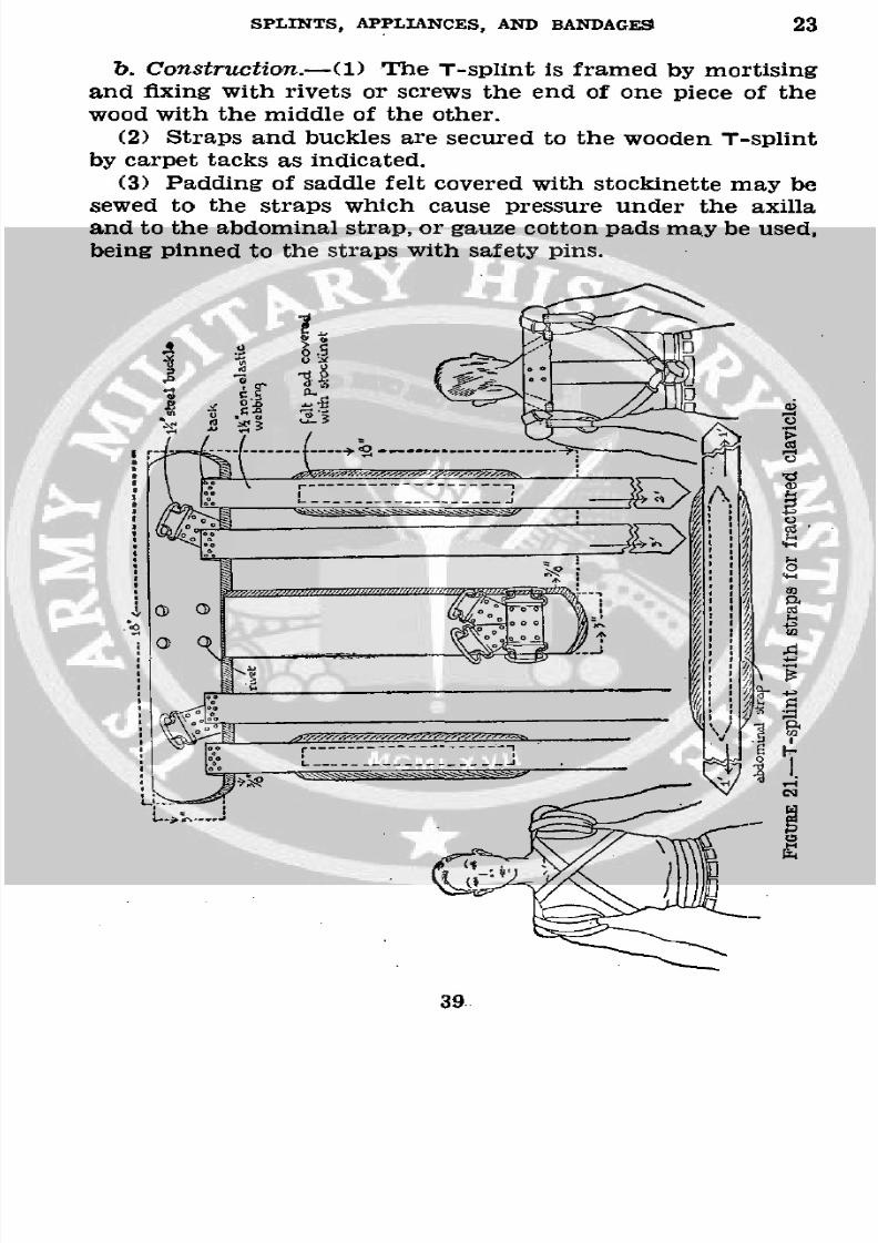
SPLINTS, APPLIANCES, AND BANDAGES 23
b. Construction.-(1) The T-splint is framed by mortisingand fixing with rivets or screws the end of one piece of thewood with the middle of the other.
(2) Straps and buckles are secured to the wooden T-splint
by carpet tacks as indicated.(3) Padding of saddle felt covered with stockinette may besewed to the straps which cause pressure under the axillaand to the abdominal strap, or gauze cotton pads may be used,being pinned to the straps with safety pins.
.faf 3 ~~~9
39.
8/7/2019 FM 8-50 1940
http://slidepdf.com/reader/full/fm-8-50-1940 44/94
23-24 MEDICAL FIELD MANUAL
(4) These dimensions are used for the average patient.
Larger, 20-inch, and smaller, 16-inch, splints should be made
up and available.
(5) For infants and young children, T-splints are made
from basswood splint board, tacked together, padded, andfixed to the child with bandages and adhesive.
c. Application.-(1) In fractures of the clavicle, the shoul-
der drops downward, forward, and inward. The proximal
fragment is usually pulled slightly anterior and upward.
(2) Traction is made upward, outward, and backward on
the shoulder to reduce the fracture. The splint is applied tomaintain immobilization.
(3) The inner strap on each side is brought up under thesplint and over the shoulder at the base of the neck of thepatient, crossed over the chest, and secured to the two upper
buckles on the lower end of the vertical arm of the splint,
The abdominal strap is applied. Both shoulders are now
pulled upward, backward, and outward by the axillary strap
and fixed in this position. Straps are adjusted daily and skin
under splint cared for.U 24. AEROPLANE OR ABDUCTION SPLINT (fig. 22) .- (Non-
standard item, made locally.)
a. Material.
Buckles, 1'/2 inch, two-prong, three.
Rod, ¼/4-inch steel, Bessemer or cold rolled, 12-foot lengths.
Sheet, aluminum, 16-gage.
Webbing, 1 /2-inch, gray, nonelastic.
b. Measurements.-(1) Width of lower end of splint, aver-
age 7 inches, convex curve.
(2) Distance from just below anterior superior spine of
ilium to anterior axillary fold.
(3) Length of arm, measured from anterior axillary fold to
flexed elbow, arm in abduction.
(4) Length of forearm, measured from flexed elbow to mid-
dle of palm of hand.(5) Line across palm, average 3 inches.
c. Construction.-(1) The ¼/4-inch steel rod is bent cold
(easily accomplished by use of vise and hammer). The rod
is joined and fixed under hand piece by fixing ends of rodin an aluminum cylinder. Aluminum cylinder formed from
40
8/7/2019 FM 8-50 1940
http://slidepdf.com/reader/full/fm-8-50-1940 45/94
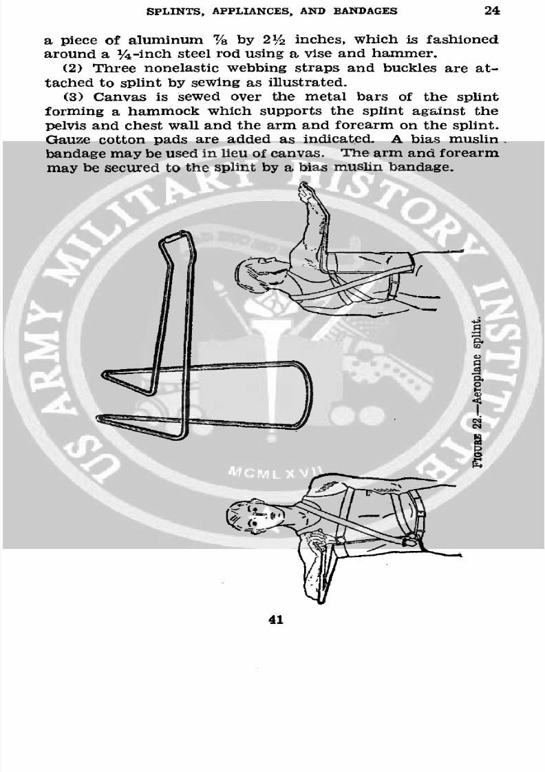
SPLINTS, APPLIANCES, AND BANDAGES 24
a piece of aluminum 7/8 by 2'/2 inches, which is fashioned
around a l/4 -inch steel rod using a vise and hammer.
(2) Three nonelastic webbing straps and buckles are at-
tached to splint by sewing as illustrated.
(3) Canvas is sewed over the metal bars of the splint
forming a hammock which supports the splint against the
pelvis and chest wall and the arm and forearm on the splint.
Gauze cotton pads are added as indicated. A bias muslin
bandage may be used in lieu of canvas. The arm and forearm
may be secured to the splint by a bias muslin bandage.
41
41
8/7/2019 FM 8-50 1940
http://slidepdf.com/reader/full/fm-8-50-1940 46/94
24-25 MEDICAL FIELD MANUAL
d. Uses.-(1) Brachial plexus injuries.
(2) Paralysis or weakness of abductor muscles of shoulder.
(3) Shoulder joint injuries (other than dislocations).
(4) Fractures of the scapula. Surgical and anatomical
neck of the humerus. Convalescent fractures of the shaft of
the humerus.
(5) Subacromial bursitis.
(6) Acromial, clavicular dislocations.
U 25. BASSWOOD SPLINT.-4 inches by A inch, 5- to 10-foot
lengths.
a. Uses.-(l) Splinting of forearm and carpal fractures.(2) Coaptation splints.
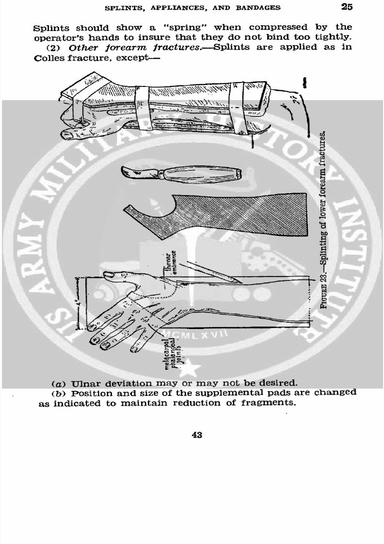
b. Cutting of splints.-(l) The good forearm and hand,with hand in ulnar deviation when splint is being prepared
in Colles fracture, is placed palm down on a piece of splint
board and outlined with pencil as shown in figure 23. The
broken line is marked in after hand is removed from board.
(2) The splint extends from just below the flexed elbow to
the metatarso-phalangeal joints, so as to allow free motion
in these joints and is cut away over the thenar eminence so
as not to produce "flat hand."(3) The posterior splint is marked out in a similar manner.
(4) The splints are now cut out from the splint board, using
a plaster knife, pocket knife, or scroll saw.
c. Padding of splints.-Sufficient layers of sheet wadding
which makes the best type of padding are laid on. each splint
and cut with a pair of bandage scissors to fit the splint. The
padding is then secured to the splints with three or morenarrow strips of adhesive.
d. Splinting of lower forearm fractures (fig. 23).-(1)Colles fracture.-The fracture is reduced, using general orlocal anesthesia. Two additional pads are formed of sheet
wadding. The longer one is placed against the proximal
fragment and the palmar splint is placed in position. Thesmaller pad is placed over the distal fragment and the dorsal
splint applied. While the splints are held in position, the firstadhesive strap, 1 to 1 /2 inches wide, is placed around thewrist, to be followed by a second one around the upper end
of the splint, and a third around the lower end securing thehand in ulnar deviation. A gauze bandage is now applied.
42
8/7/2019 FM 8-50 1940
http://slidepdf.com/reader/full/fm-8-50-1940 47/94
SPLINTS, APPLIANCES, AND BANDAGES 25
Splints should show a "spring" when compressed by the
operator's hands to insure that they do not bind too tightly.
(2) Other forearm fractures.-Splints are applied as in
Colles fracture, except-
ai
Eq
~4
(a)ar deviation may or m ay not be desired.
(a) Ulnar deviation may or may not be desired.
(b) Position and size of the supplemental pads are changed
as indicated to maintain reduction of fragments.
43
8/7/2019 FM 8-50 1940
http://slidepdf.com/reader/full/fm-8-50-1940 48/94
26 MEDICAL FIELD MANUAL
U 26. PLASTER OF PARIS (4-lb. tins).-a. Specifications.-Or-thopedic plaster will have a compression strength of not
less than 2,400 pounds per square inch. It shall set in not less
than 6 minutes nor more than 15 minutes. The label shouldindicate the water plaster ratio for obtaining the testing con-
sistency. Good results depend upon the proper proportion ofwater.
b. Bandages (5 inches by 5 yards).-One dozen sealed inmetal container, each bandage individually wrapped in wax
paper or equivalent field item.
(1) Material.-Sixyards of crinoline, 1 yard wide, to con-
tain 32 by 28 threads per square inch. Only starch sizing to
be used and not to excess. Torn in strips, six to the bolt,each 6 yards long, the selvaged edge is removed and all loosethreads from the frayed edges. Each strip is rolled in bandage
form.
(2) To make bandages.-Plaster of paris is placed on a
table before which is seated the operator who works theplaster into the prepared 5-inch by 6-yard strip of crinoline.
With the right hand, plaster of paris is placed on the crinoline
and worked into its meshes, the excess being removed by aspatula, while with the left hand, the crinoline with its con-
tained plaster is rolled into a bandage. An inverted bowl may
be used to work the plaster into the bandage and remove
excess. If the bandage is rolled too tightly, it will not takeup sufficient water to become properly wet through; if rolled
too loosely, it cannot be handled; if too much plaster is incor-porated, it will become "lumpy"; when insufficient is used, thecast from which it is made will be weak and unsatisfactory.
The average weight of a satisfactory plaster of paris bandageof this size is 8 ounces.
c. Care.-(1) Plaster of paris is prepared by heating gyp-
sum until three-fourths of the water of crystallization isdriven off under definite heat control and is then ground to afine powder. If not properly heated or ground, poor plaster
of paris is the result. It tends to take up moisture from theatmosphere and "set," that is, return to gypsum, so that it
must be kept dry at all times. The plaster falls from themeshes of the crinoline if handled roughly.
44
8/7/2019 FM 8-50 1940
http://slidepdf.com/reader/full/fm-8-50-1940 49/94
SPLINTS, APPLIANCES, AND BANDAGES 26-27
(2) A pail type commode is an excellent container in which
to seal plaster bandages.
(3) Plaster of paris not in bandage form is kept in the
original 4-pound tin until used.
* 27. PLASTER CASTS.-a. Material.
Plaster bandages.
Stockinette, 3-inch, 6-inch, and 9-inch.
Wadding, sheet (5-inch by 5-yard rolls).
Knife, plaster.Shears, plaster of paris, Stille.
Felt, soft, gray, /2-inch.
b. Application.-Casts may be applied to the extremitieswithout padding by molding directly against the unshaven
skin. When padding is used, sheet wadding is necessary.
It is nonabsorbing and ideal. Stockinette is always used next
to the skin in body casts and hip spicas. It may or may not be
used, as desired, on the extremities. Felt is used as addi-
tional padding in body casts and hip spicas, covered by cotton
wadding. Absorbent or nonabsorbent cotton should not be
used under plaster, as it takes up and retains moisture,preventing the proper setting of the plaster.
c. Handling of plaster bandages.-(l) The water in which
bandages are placed should be warm. Cold water delays
setting of plaster; hot water hastens setting. The bandages
should be set on end in a bucket of water and completely
submerged. They should not be handled or removed until all
bubbles cease to appear. If allowed to soak too long the plas-
ter will "set" in the water. The excess water is expelled by
grasping each end of the bandage and squeezing toward thecenter.
(2) Plaster bandages may be applied circularly about the
body or extremity, rubbing the plaster in with each turnforming a cast or casing. The points of greatest stress where
breaking is feared may be reinforced by plaster slabs. These
slabs are made by running plaster bandage back and forthon itself on a flat board for the desired length and thicknessand rubbing the layers well with the hand. Reinforcement
of casts with metal or wood is not necessary and should beavoided.
45
8/7/2019 FM 8-50 1940
http://slidepdf.com/reader/full/fm-8-50-1940 50/94
27-28 MEDICAL FIELD MANUAL
(3) Molded plaster splints are made in the same manner;
slabs are cut to the desired size, molded to the part to be
splinted, and fixed in this position until set.
(4) Plaster splints are often indicated in Colles fractures,
and plaster is usually applied in this form when a nonpaddedcast is desired.
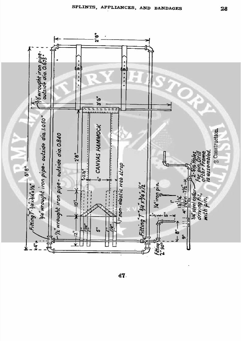
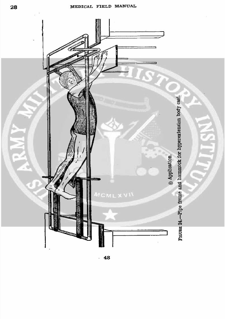
* 28. PIPE FRAME AND HAMMOCK FOR HYPEREXTENSION BODY
CAST (fig. 24 O).-(Nonstandard item, made locally.)
a. Construction.-Pipe frame and windlass are made of
3/4-inch wrought iron pipe, elbows, and T-joints and can
be made by any plumber or pipe fitter. Canvas for hammock
is type used on the standard litter. One-inch nonelasticwebbing is sewed to the canvas so as to fix it to the shaft
or windlass of the frame.
b. Uses.-(1) For suspension of patient for application of
body cast or plaster shells in lesions of spine below dorsal
vertebrae particularly when hyperextension is desired.
(2) Compression fractures.
(3) Tuberculous spondylitis.
(4) Fractures of lamina and transverse processes.
(5) In lesions at or above the 6th dorsal vertebrae, the head
must be incorporated in plaster so that overhead jury masktraction is used for suspension whilD the cast is applied.
c. Application (fig. 240i ).-(1). The two ends of the pipeframe are placed on tables. A piece of 9-inch stockinette, cut
of proper length, and with slits for armholes is rolled on itself
and placed over the canvas hammock.(2) The lower end of the canvas is fixed to the leather
straps by inserting a piece of 3/8-inch pipe. The webbing
straps are threaded through the four slots in the shaft, theshaft turned by the handle, fixing the straps on themselves
by friction and the canvas made taut. The shaft is fixed by
the iron pin.
(3) The patient is laid face down with head between straps
and the shaft and stockinette brought down over the patient'sbody.
(4) The desired amount of hyperextension is obtained by
loosening or tightening the shaft; the body is properly padded
and the cast or shell applied.
46
8/7/2019 FM 8-50 1940
http://slidepdf.com/reader/full/fm-8-50-1940 51/94
SPLINTS, APPLIANCES, AND BANDAGES 28
e II I ' ~ .
.c
t00=
a ;u~~~~~~~~~~'
s 0
Z9`1r
_x ""P" I t: ~~~~~~~~~~~~Se-~~~~A
o 11 ~~~~~~~~~~4 o;'~~~~~lh ,
8/7/2019 FM 8-50 1940
http://slidepdf.com/reader/full/fm-8-50-1940 52/94
28 MEDICAL FIELD MANUAL
I
0
t,~~~~~~~~~~~~~~~~~~~~~~~~0
Q
0EQ
r.0
0.
wm
C4
0
I4
-48
8/7/2019 FM 8-50 1940
http://slidepdf.com/reader/full/fm-8-50-1940 53/94
SPLINTS, APPLIANCES, AND BANDAGES 28-29
(5) When the cast has dried sufficiently, the rod connect-ing the leather straps and canvas and the webbing straps
from the shaft are removed while the patient is supported by
attendants. He is then placed on his back on a wheel litter
or bed and the canvas removed.
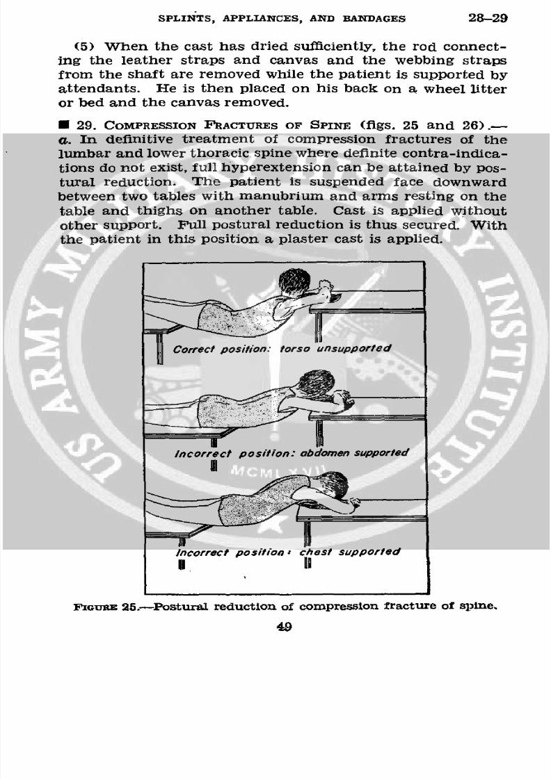
* 29. COMPRESSION FRACTURES OF SPINE (figs. 25 and 26).-
a. In definitive treatment of compression fractures of thelumbar and lower thoracic spine where definite contra-indica-
tions do not exist, full hyperextension can be attained by pos-
tural reduction. The patient is suspended face downward
between two tables with manubrium and arms resting on the
table and thighs on another table. Cast is applied withoutother support. Full postural reduction is thus secured. With
the patient in this position a plaster cast is applied.
Correct position: torso unsupported
Incorrect position:abdomen supported
Incorrect position -chest supported
FGluRE 25.-Postural reduction of compression fracture of spine.
49
8/7/2019 FM 8-50 1940
http://slidepdf.com/reader/full/fm-8-50-1940 54/94
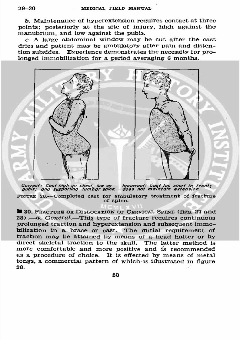
29-30 MEDICAL FIELD MANUAL
b. Maintenance of hyperextension requires contact at threepoints; posteriorly at the site of injury, high against themanubrium, and low against the pubis.
c. A large abdominal window may be cut after the cast
dries and patient may be ambulatory after pain and disten-tion subsides. Experience demonstrates the necessity for pro-
longed immobilization for a period averaging 6 months.
Correctow on Inorrec Cost too sor in front;
ps; nd supporrect:ost high on chest low on Incorrect Costnin frontpubis; and supporting lumbar spine, does not maintain extension.
FIGURE 26.-Completed cast for ambulatory treatment of fractureof spine.
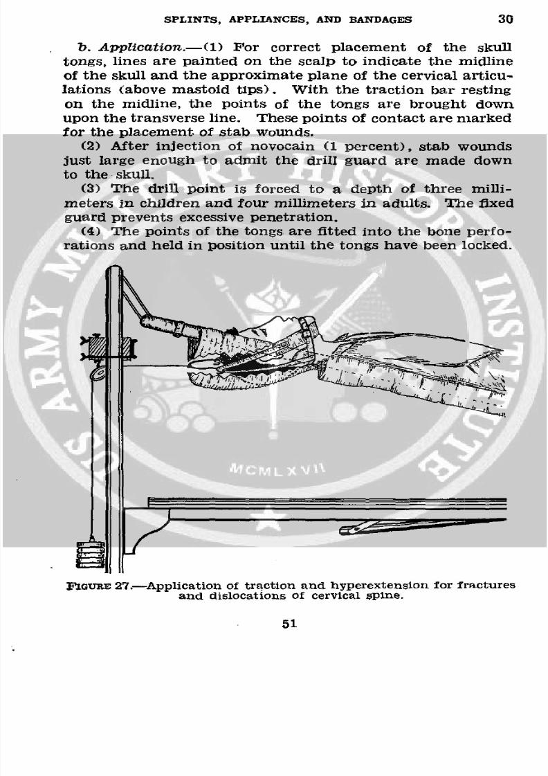
· 30. FRACTURE OR DISLOCATION OF CERVICAL SPINE (figs. 27 and
28) .- a. General.-This type of fracture requires continuous
prolonged traction and hyperextension and subsequent immo-
bilization in a brace or cast. The initial requirement oftraction may be attained by means of a head halter or bydirect skeletal traction. to the skull. The latter method ismore comfortable and more positive and is recommended
as a procedure of choice. It is effected by means of metaltongs, a commercial pattern of which is illustrated in figure
28.
50
8/7/2019 FM 8-50 1940
http://slidepdf.com/reader/full/fm-8-50-1940 55/94
SPLINTS, APPLIANCES, AND BANDAGES 30
b. Application.-(1) For correct placement of the skull
tongs, lines are painted on the scalp to indicate the midline
of the skull and the approximate plane of the cervical articu-lations (above mastoid tips). With the traction bar resting
on the midline, the points of the tongs are brought downupon the transverse line. These points of contact are marked
for the placement of stab wounds.
(2) After injection of novocain (1 percent), stab wounds
just large enough to admit the drill guard are made down
to the skull.
(3) The drill point is forced to a depth of three milli-
meters in children and four millimeters in adults. The fixed
guard prevents excessive penetration.(4) The points of the tongs are fitted into the bone perfo-
rations and held in position until the tongs have been locked.
FiGuREE 27.-Application of traction and hyperextension for fracturesand dislocations of cervical Spine.
51
8/7/2019 FM 8-50 1940
http://slidepdf.com/reader/full/fm-8-50-1940 56/94
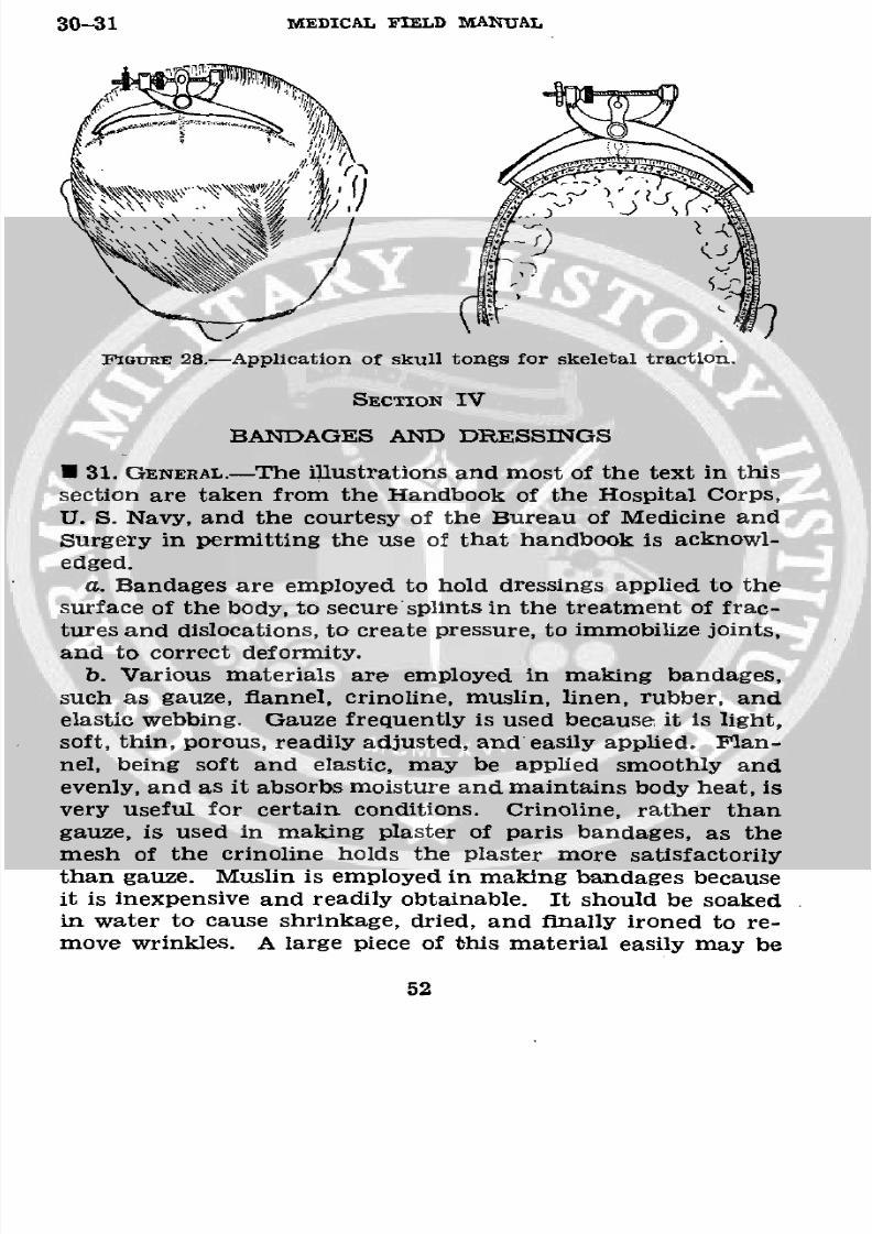
30-31 MEDICAL FIELD MANUAL
FGURE 28.-Application of skull tongs for skeletal traction.
SECTION IV
BANDAGES AND DRESSINGS
U 31. GENERAL.-The illustrations and most of the text in this
section are taken from the Handbook of the Hospital Corps,
U. S. Navy, and the courtesy of the Bureau of Medicine and
Surgery in permitting the use of that handbook is acknowl-
edged.
a. Bandages are employed to hold dressings applied to thesurface of the body, to secure'splints in the treatment of frac-
tures and dislocations, to create pressure, to immobilize joints,and to correct deformity.
b. Various materials are employed in making bandages,such as gauze, flannel, crinoline, muslin, linen, rubber, andelastic webbing. Gauze frequently is used because it is light,
soft, thin, porous, readily adjusted, and' easily applied. flan-
nel, being soft and elastic, may be applied smoothly and
evenly, and as it absorbs moisture and maintains body heat, is
very useful for certain conditions. Crinoline, rather thangauze, is used in making plaster of paris bandages, as the
mesh of the crinoline holds the plaster more satisfactorily
than gauze. Muslin is employed in making bandages because
it is inexpensive and readily obtainable. It should be soaked
in water to cause shrinkage, dried, and finally ironed to re-
move wrinkles. A large piece of this material easily may be
52
8/7/2019 FM 8-50 1940
http://slidepdf.com/reader/full/fm-8-50-1940 57/94
SPLINTS, APPLIANCES, AND BANDAGES 31
torn into strips of the desired width. Rubber and elastic
webbing are used to afford firm support to a part. The web-
bing is preferable to the pure rubber bandage, as it permits
the evaporation of moisture.
c. It is of the greatest importance that an enlisted man,Medical Department, should become familiar with the general
rules of bandaging and proficient in the application of vari-
ous types of bandages. The comfort of a patient, security of
the dressing, and professional reputation of the Medical De-
partment depend upon proper application of a bandage. A
neatly and properly applied bandage is an indication that
the dressing covered by the bandage has been properly
performed. An untidy, uncomfortable, insecure, improperlyapplied bandage reasonably may lead one to suspect thatthe underlying dressing is of the same character and can
result only in adverse criticism.
d. Various types of bandages, commonly used, are the roller
bandage, the triangular bandage, and the many-tailed band-
age. The roller bandage is made from one of the ma-
terials mentioned in b above, the width and length depending
upon the part to be bandaged. For convenience and ease ofapplication, the strip of material is rolled into the form of a
cylinder. Each bandage of this type should consist of only
one piece, free from wrinkles, seams, selvage, and any im-
perfections that may cause discomfort to the patient. Al-
though there are various types of mechanical appliances used
in winding bandages, it is essential that enlisted men be able
to roll a bandage by hand.e. The strips of bandage material should be folded at one
extremity several times to form a small, firm cylinder. This
cylinder is held by its extremities with the index finger and
thumb of the left hand. The free end of the bandage is held
between the index finger and thumb of the right hand, closeto the cylinder. With this hand, the bandage then is revolved
around the cylinder which is held in the left hand, the free
fingers of which aid in turning the cylindrical roll. Theamount of tension exerted upon the free end will determine
the firmness of the completed roller. A roller bandage con-
sists of the free end or initial extremity, the body, and theterminal extremity in the center of the cylinder.
53
8/7/2019 FM 8-50 1940
http://slidepdf.com/reader/full/fm-8-50-1940 58/94
31-32 MEDICAL FIELD MANUAL
I. The length and width of bandages vary according to the
purposes for which they are employed. The sizes most fre-
quently used are 1 inch wide, 3 yards long, for the hand,
fingers, and toes; 2 inches wide, 6 yards long, for head band-
ages; 21/2 inches wide, 7 yards long, for extremities; 3 incheswide, 9 yards long, for thigh, groin, and trunk.
* 32. RULES FOR BANDAGING.--4. In applying a roller bandage,
the roll should be held in the right hand so that the loose end
is on the bottom; the outside surface of the loose or initial end
is next applied to and held on the part by the left hand; andthe roll is then passed around the part by the right hand
which controls the tension and application of the bandage.Two or three of the initial turns of a roller bandage should
overlie each other in order to secure the bandage and keep
it in place. In applying the turns of the bandage, it is often
necessary to transfer the roll from one hand to the other.
b. Bandages should be applied evenly, firmly, and not too
tightly. Excessive pressure may cause interference with thecirculation and may lead to disastrous consequences. In
bandaging an extremity, it is therefore advisable to leave thefingers or toes exposed in order that the circulation of these
parts may be readily observed. It is likewise safer to apply alarge number of turns of a bandage rather than to depend
upon a few too firmly applied turns to secure a splint or
dressing.
c. In applying a wet bandage, or one that may become wet
in holding a wet dressing in place, it is necessary to allow forshrinkage. The turns of a bandage should completely cover
the skin, as any uncovered areas of skin may become pinched
between the turns with resulting discomfort.
d. Bandages should be applied in such a manner that skin
surfaces are not brought in contact, as perspiration will cause
excoriation and maceration of the skin.
e. In bandaging an extremity, it is advisable to include the
whole member (arm and hand, leg and foot), except thefingers and toes, in order that uniform pressure may be main-
tained throughout. It is also desirable in bandaging a limb
that the part be placed in the position it will occupy when thedressing is finally completed, as variations in flexion or exten-
54
8/7/2019 FM 8-50 1940
http://slidepdf.com/reader/full/fm-8-50-1940 59/94
SPLINTS, APPLIANCES, AND BANDAGES 32-33
sion of the part will cause changes in the pressure of certain
parts of the bandage.
f. The initial turns of a bandage of an extremity (includ-
ing spica bandages of the hip and shoulder) always should beapplied securely, and when possible, around the part of thelimb that has the smallest circumference. Thus in bandaging
the arm or hand, the initial turns usually are applied around
the wrist, and in bandaging the leg or foot, the initial turnsare applied immediately above the ankle.
g. The final turns of a completed bandage usually are se-
cured in the same manner as are the initial turns, by the
employment of two or more overlying circular turns. As bothedges of the final circular turn are necessarily exposed, theyshould be folded under to present a-neat, cuff-like appearance.
The terminal end of the completed bandage is turned under
and secured to the final turns by either a safetypin or ad-
hesive tape. When these are not available, the end of the
bandage may be split lengthwise for several inches, and the
two resulting tails secured around the part by tying.h. When the turns of a bandage cross each other, as in
the figure-of-eight, the spiral reverse, and the spica, the line
of crossings should be straight, and if practicable, should be in
the center line of the part bandaged, but the line of crossings
should not be over a bony prominence. The exposed portions
of the turns should be of approximately the same width.
i. In removing a bandage, it may be cut, preferably with
bandage scissors. In doing so the operator should be carefulto avoid interference with the underlying dressing and theaffected area.
j. If the bandage is removed without cutting, its folds
should be gathered up in first one hand and then the other
as the bandage is unwound. This procedure will facilitate
removal and the rewinding of the bandage, if that be desirable.
* 33. APPLICATION OF BANDAGES AND THEIR USES.-a. Circularbandage.-After anchoring the initial turns of the bandage,
a series of circular turns is made around the part. Each
turn should overlie accurately the turn beneath it, neither
ascending nor descending. This bandage is used for reten-tion of dressings to a limited portion of an extremity, the
55
8/7/2019 FM 8-50 1940
http://slidepdf.com/reader/full/fm-8-50-1940 60/94
33 MEDICAL FIELD MANUAL
neck, or the head; compression to control venous hemorrhageand to promote venous stasis.
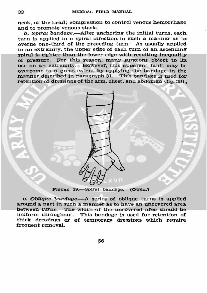
b. Spiral bandage.-After anchoring the initial turns, each
turn is applied in a spiral direction in such a manner as tooverlie one-third of the preceding turn. As usually appliedto an extremity, the upper edge of each turn of an ascendingspiral is tighter than the lower edge with resulting inequalityof pressure. For this reason, many surgeons object to itsuse on an extremity. However, this apparent fault may beovercome to a great extent by applying the bandage in themanner described in paragraph 31. This bandage is used for
retention of dressings of the arm, chest, and abdomen (fig. 29).
TGURE 29.-Spiral bandage. (Owen.)
c. Oblique bandage.-A series of oblique turns is applied
around a part in such a manner as to have an uncovered areabetween turns. The width of the uncovered area should beuniform throughout. This bandage is used for retention ofthick dressings or of temporary dressings which requirefrequent removal.
56
8/7/2019 FM 8-50 1940
http://slidepdf.com/reader/full/fm-8-50-1940 61/94
SPLINTS, APPLIANCES, AND BANDAGES 33
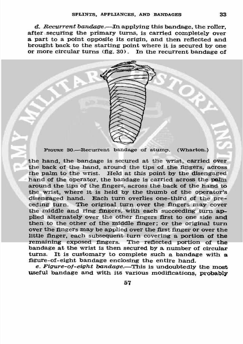
d. Recurrentbandage.-napplying this bandage, the roller,
after.securing the primary turns, is carried completely overa part to a point opposite its origin, and then reflected and
brought back to the starting point where it is secured by oneor more circular turns (fig. 30). In the recurrent bandage of
'IGURE 30.-Recurrent bandage of stump. (Wharton.)
the hand, the bandage is secured at the wrist, carried overthe back of the hand, around the tips of the fingers, acrossthe palm to the wrist. Held at this point by the disengaged
hand of the operator, the bandage is carried across the palm
around the tips of the fingers, across the back of the hand to
the wrist, where it is held by the thumb of the operator'sdisengaged hand. Each turn overlies one-third of the pre-
ceding turn. The original turn over the fingers may' cover
the middle and ring fingers, with each succeeding turn ap-plied alternately over the other fingers first to one side and
then to the other of the middle finger; or the original turnover the fingers may be applied over the first finger or over the
little finger, each subsequent turn covering a portion of theremaining exposed fingers. The reflected portion of thebandage at the wrist is then secured by a number of circular
turns. It is customary to complete such a bandage with afigure-of-eight bandage enclosing the entire hand.
e. Figure-of-eight bandage.-This is undoubtedly the mostuseful bandage and with its various modifications, probakbly
57
8/7/2019 FM 8-50 1940
http://slidepdf.com/reader/full/fm-8-50-1940 62/94
33 MEDICAL FIELD MANUAL
is employed more frequently than any other type. The en-
listed man should perfect himself in the application of this
bandage, as, with a few exceptions, the majority of bandages
are applied on the principle of the figure-of-eight. Its nameis derived from the fact that the turns are applied so as to
form a figure 8. Although it is employed commonly in band-
ages of the joints (elbow, knee, and ankle), it frequently is
applied in bandaging the neck and axilla, head and neck, and
head and jaw. If properly applied, it may be used very
successfully in bandaging the extremities.
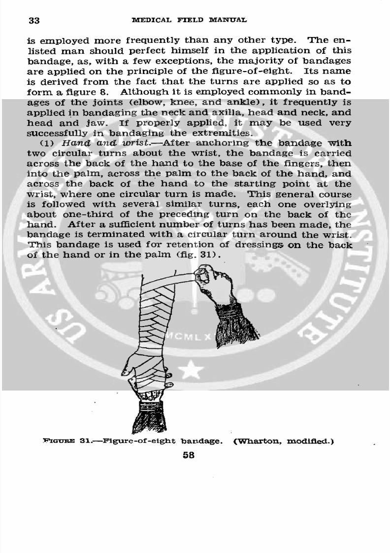
(1) Hand and wrist.-After anchoring the bandage withtwo circular turns about the wrist, the bandage is carriedacross the back of the hand to the base of the fingers, then
into the palm, across the palm to the back of the hand, andacross the back of the hand to the starting point at the
wrist, where one circular turn is made. This general course
is followed with several similar turns, each one overlying
about one-third of the preceding turn on the back of the
hand. After a sufficient number of turns has been made, thebandage is terminated with a circular turn around the wrist.
This bandage is used for retention of dressings on the back
of the hand or in the palm (fig. 31).
?TGUvE 31.-lFigure-of-eight bandage. (Wharton, modified.)
58
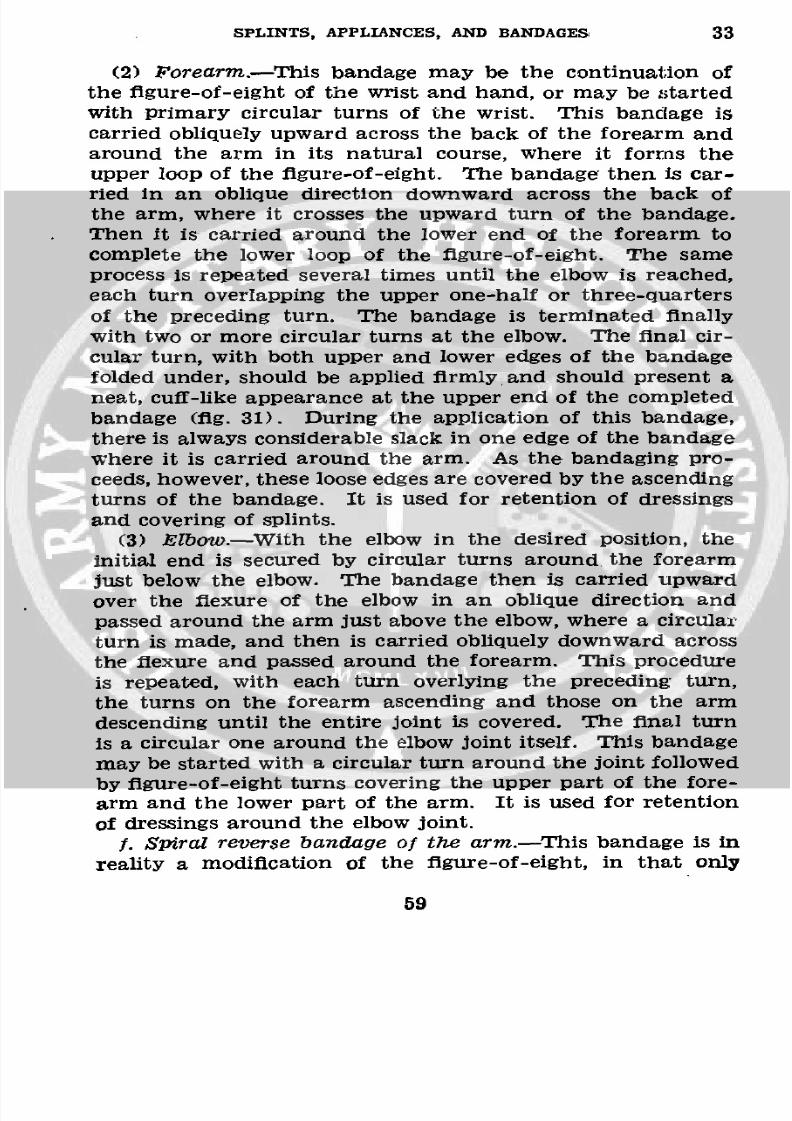
8/7/2019 FM 8-50 1940
http://slidepdf.com/reader/full/fm-8-50-1940 63/94
SPLINTS, APPLIANCES, AND BANDAGES 33
(2) Forearm.-Thisbandage may be the continuation of
the figure-of-eight of the wrist and hand, or may be started
with primary circular turns of the wrist. This bandage is
carried obliquely upward across the back of the forearm and
around the arm in its natural course, where it forms theupper loop of the figure-of-eight. The bandage then is car-
ried in an oblique direction downward across the back of
the arm, where it crosses the upward turn of the bandage.
Then it is carried around the lower end of the forearm to
complete the lower loop of the figure-of-eight. The same
process is repeated several times until the elbow is reached,
each turn overlapping the upper one-half or three-quarters
of the preceding turn. The bandage is terminated finally
with two or more circular turns at the elbow. The final cir-
cular turn, with both upper and lower edges of the bandage
folded under, should be applied firmly and should present a
neat, cuff-like appearance at the upper end of the completed
bandage (fig. 31). During the application of this bandage,
there is always considerable slack in one edge of the bandage
where it is carried around the arm. As the bandaging pro-ceeds, however, these loose edges are covered by the ascending
turns of the bandage. It is used for retention of dressings
and covering of splints.
(3) Elbow.-With the elbow in the desired position, the
initial end is secured by circular turns around the forearm
just below the elbow. The bandage then is carried upward
over the flexure of the elbow in an oblique direction and
passed around the arm just above the elbow, where a circularturn is made, and then is carried obliquely downward across
the flexure and passed around the forearm. This procedure
is repeated, with each turn overlying the preceding turn,the turns on the forearm ascending and those on the arm
descending until the entire joint is covered. The final turn
is a circular one around the elbow joint itself. This bandage
may be started with a circular turn around the joint followed
by figure-of-eight turns covering the upper part of the fore-arm and the lower part of the arm. It is used for retention
of dressings around the elbow joint.f. Spiral reverse bandage of the arm.-This bandage is in
reality a modification of the figure-of-eight, in that only
59
8/7/2019 FM 8-50 1940
http://slidepdf.com/reader/full/fm-8-50-1940 64/94
33 MEDICAL FIELD MANUAL
the lower loop or one-half of the figure-of-eight is com-
pleted. After anchoring the primary turns, the bandage iscarried obliquely upward on the back of the arm. When
this turn reaches the center line of the arm, the thumb of
the disengaged (usually the left) hand is placed upon thebody of the bandage to hold it securely in place upon thearm. The operator then unrolls about 5 or 6 inches of band-age which is held slack and is folded upon itself by changingthe position of the hand holding the roller from supinationto pronation. The bandage then is carried obliquely down-ward across the arm to a point opposite that from whichthe ascending turn started. It then is tightened slightlyto conform to the part accurately, then is carried aroundthe limb and the procedure is repeated. It is necessary toretain the thumb upon the point of reverse until the suc-
ceeding turn reaches that point. As in the figure-of-eight,
each turn should overlie at least one-third of the preceding
turn and the reverses should be in a straight line (fig. 32).
FIcGRE 32.-Spiral reverse.' (Eliason.)
g. Complete bandage of the hand.-After securing theinitial turns around the wrist, a recurrent bandage of thehand is applied. The bandage then is carried obliquely
across the back of the hand to the tip of the index finger.A circular turn is made around the ends of the fingers. The
60
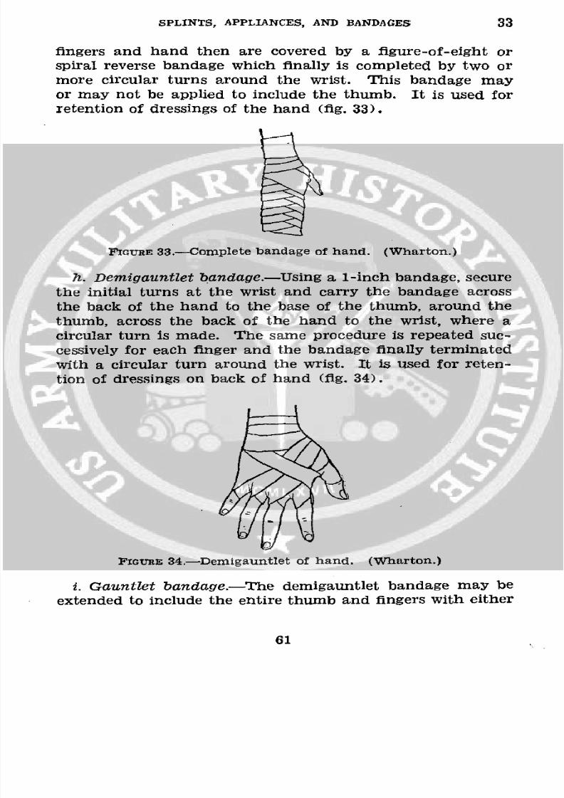
8/7/2019 FM 8-50 1940
http://slidepdf.com/reader/full/fm-8-50-1940 65/94
SPLINTS, APPLIANCES, AND BANDAGES 33
fingers and hand then are covered by a figure-of-eight or
spiral reverse bandage which finally is completed by two or
more circular turns around the wrist. This bandage may
or may not be applied to include the thumb. It is used for
retention of dressings of the hand (fig. 33).
nIGURE 33.-Complete bandage of hand. (Wharton.)
h. Demigauntlet bandage.-Usinga 1-inch bandage, secure
the initial turns at the wrist and carry the bandage across
the back of the hand to the base of the thumb, around the
thumb, across the back of the hand to the wrist, where a
circular turn is made. The same procedure is repeated suc-
cessively for each finger and the bandage finally terminated
with a circular turn around the wrist. It is used for reten-
tion of dressings on back of hand (fig. 34).
FIGURE 34.-Demigauntlet of hand. (Wharton.)
i. Gauntlet bandage.-The demigauntlet bandage may be
extended to include the entire thumb and fingers with either
61
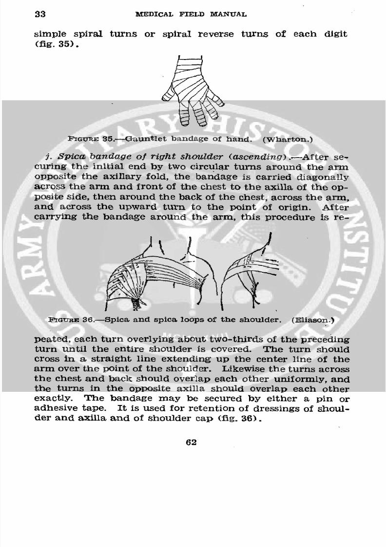
8/7/2019 FM 8-50 1940
http://slidepdf.com/reader/full/fm-8-50-1940 66/94
33 MEDICAL FIELD MANUAL
simple spiral turns or spiral reverse turns of each digit
(fig. 35).
P'IGuE 35.--Gauntlet bandage of hand. (Wharton.)
j. Spica bandage of right shoulder (ascending) .- After se-
curing the initial end by two circular turns around the armopposite the axillary fold, the bandage is carried diagonallyacross the arm and front of the chest to the axilla of the op-
posite side, then around the back of the chest, across the arm,and across the upward turn to the point of origin. Aftercarrying the bandage around the arm, this procedure is re-
FGuRE 36.-Spica and spica loops of the shoulder. (Eliason.)
peated, each turn overlying about two-thirds of the precedingturn until the entire shoulder is covered. The turn shouldcross in a straight line extending up the center line of thearm over the point of the shoulder. Likewise the turns across
the chest and back should overlap each other uniformly, andthe turns in the opposite axilla should overlap each otherexactly. The bandage may be secured by either a pin oradhesive tape. It is used for retention of dressings of shoul-der and axilla and of shoulder cap (fig. 36).
62
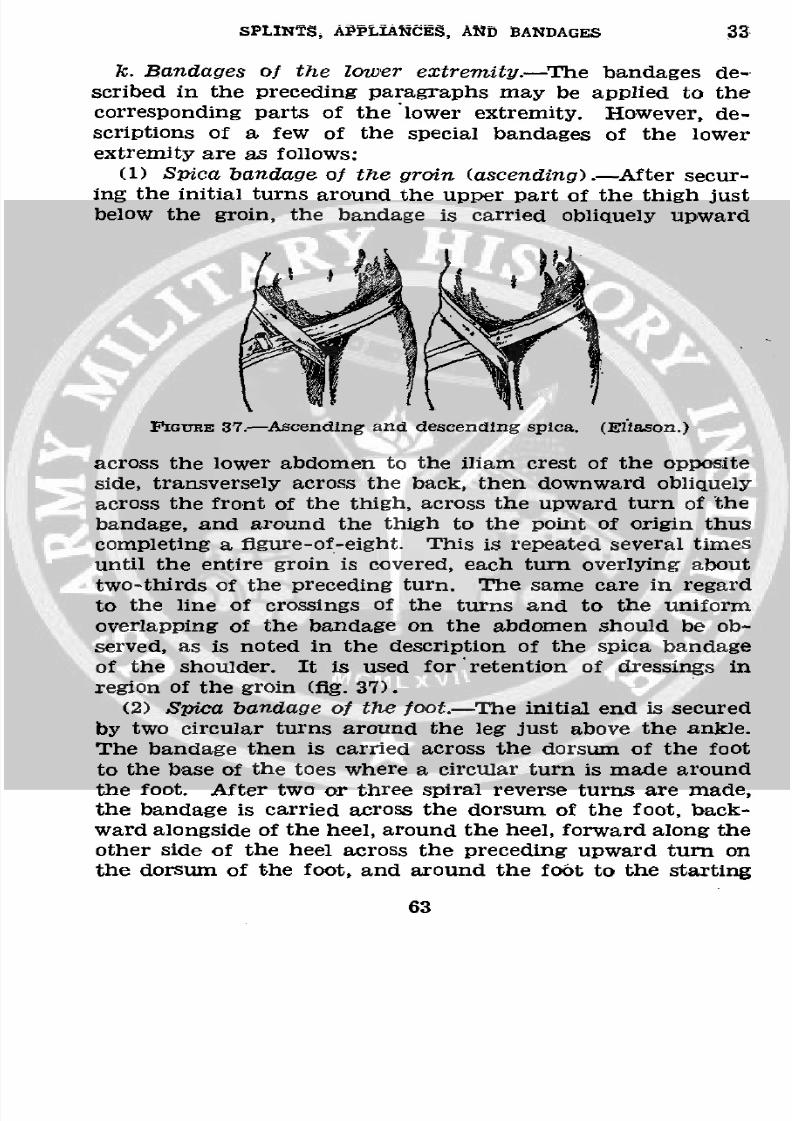
8/7/2019 FM 8-50 1940
http://slidepdf.com/reader/full/fm-8-50-1940 67/94
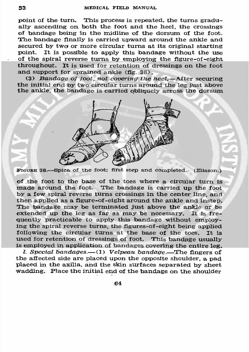
8/7/2019 FM 8-50 1940
http://slidepdf.com/reader/full/fm-8-50-1940 68/94
33 MEDICAL FIELD MANUAL
point of the turn. This process is repeated, the turns gradu-
ally ascending on both the foot and the heel, the crossingsof bandage being in the midline of the dorsum of the foot.
The bandage finally is carried upward around the ankle and
secured by two or more circular turns at its original startingpoint. It is possible to apply this bandage without the use
of the spiral reverse turns by employing the figure-of-eightthroughout. It is used for retention of dressings on the foot
and support for sprained ankle (fig. 38).
(3) Bandage of foot, not covering the heel.-After securing
the initial end by two circular turns around the leg just abovethe ankle, the bandage is carried obliquely across the dorsum
nGTuIE 38.-Spica of the foot; first step and completed. (Eliason.)
of the foot to the base of the toes where a circular turn is
made around the foot. The bandage is carried up the foot
by a few spiral reverse turns crossings in the center line, andthen applied as a figure-of-eight around the ankle and instep.
The bandage may be terminated just above the ankle or beextended up the leg as far as may be necessary. It is fre-
quently practicable to apply this bandage without employ-ing the spiral reverse turns, the figures-of-eight being applied
following the circular turns at the base of the toes. It is
used for retention of dressings of foot. This bandage usuallyis employed in application of bandages covering the entire leg.
1. Special bandages.-(1) Velpeau bandage.-The fingers ofthe affected side are placed upon the opposite shoulder, a pad
placed in the axilla, and the skin surfaces separated by sheet
wadding. Place the initial end of the bandage on the shoulder
64
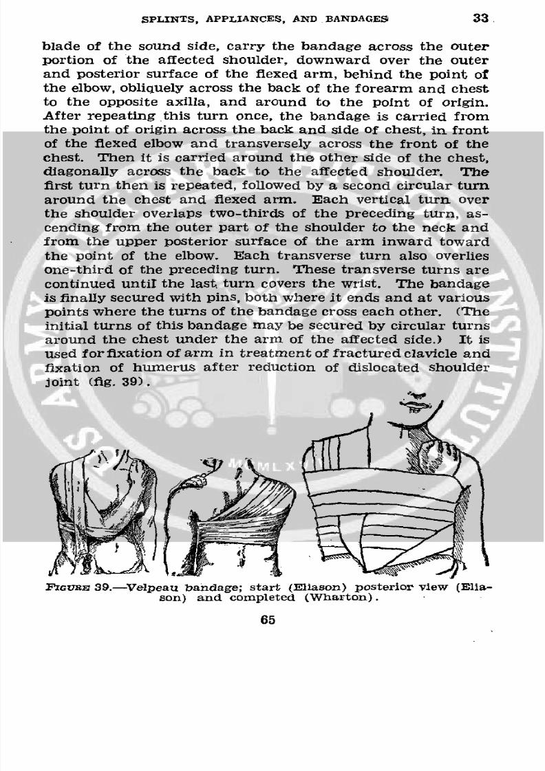
8/7/2019 FM 8-50 1940
http://slidepdf.com/reader/full/fm-8-50-1940 69/94
SPLINTS, APPLIANCES, AND BANDAGES 33.
blade of the sound side, carry the bandage across the outerportion of the affected shoulder, downward over the outer
and posterior surface of the flexed arm, behind the point ofthe elbow, obliquely across the back of the forearm and chest
to the opposite axilla, and around to the point of origin.After repeating this turn once, the bandage is carried from
the point of origin across the back and side of chest, in frontof the flexed elbow and transversely across the front of thechest. Then it is carried around the other side of the chest,
diagonally across the back to the affected shoulder. Thefirst turn then is repeated, followed by a second circular turn
around the chest and flexed arm. Each vertical turn over
the shoulder overlaps two-thirds of the preceding turn, as-cending from the outer part of the shoulder to the neck and
from the upper posterior surface of the arm inward toward
the point of the elbow. Each transverse turn also overlies
one-third of the preceding turn. These transverse turns are
continued until the last turn covers the wrist. The bandage
is finally secured with pins, both where it ends and at various
points where the turns of the bandage cross each other. (Theinitial turns of this bandage may be secured by circular turnsaround the chest under the arm of the affected side.) It is
used for fixation of arm in treatment of fractured clavicle and
fixation of humerus after reduction of dislocated shoulder
joint (fig. 39).
FIGTJRE 39.-Velpeau bandage; start (Eliason) posterior view (Ella-
son) and completed (Wharton).
65
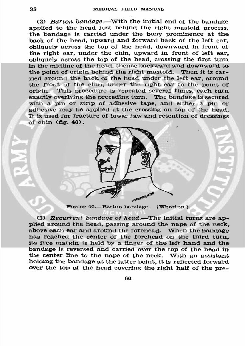
8/7/2019 FM 8-50 1940
http://slidepdf.com/reader/full/fm-8-50-1940 70/94
33 MEDICAL FIELD MANUAL
(2) Barton bandage.-With the initial end of the bandage
applied to the head just behind the right mastoid process,
the bandage is carried under the bony prominence at theback of the head, upward and forward back of the left ear,
obliquely across the top of the head, downward in front ofthe right ear, under the chin, upward in front of left ear,
obliquely across the top of the head, crossing the first turnin the midline of the head, thence backward and downward tothe point of origin behind the right mastoid. Then it is car-
ried around the back of the head under the left ear, aroundthe front of the chin, under the right ear to the point of
origin. This procedure is repeated several times, each turnexactly overlying the preceding turn. The bandage is secured
with a pin or strip of adhesive tape, and either a pin or
adhesive may be applied at the crossing on top of the head.
It is used for fracture of lower jaw and retention of dressings
of chin (fig. 40).
lGmcruE 0.-Barton bandage. (Wharton.)
(3) REecurrent bandageof head.-The initial turns are ap-plied around the head, passing around the nape of the neck,
above each ear and around the forehead. When the bandage
has reached the center of the forehead on the third turn,its free margin is held by a finger of the left hand and thebandage is reversed and carried over the top of the head in
the center line to the nape of the neck. With an assistantholding the bandage at the latter point, it is reflected forward
over the top of the head covering the right half of the pre-
66
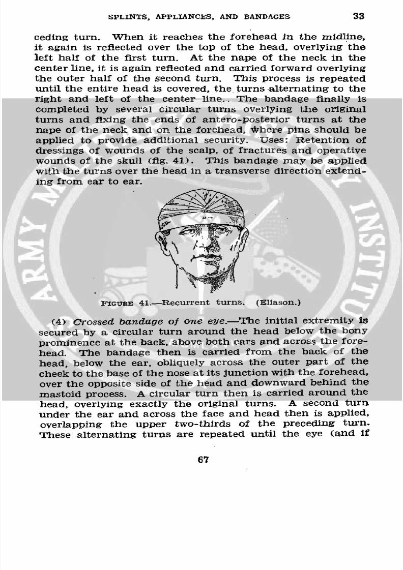
8/7/2019 FM 8-50 1940
http://slidepdf.com/reader/full/fm-8-50-1940 71/94
SPLINTS, APPLIANCES, AND BANDAGES 33
ceding turn. When it reaches the forehead in the midline,
it again is reflected over the top of the head, overlying the
left half of the first turn. At the nape of the neck in the
center line, it is again reflected and carried forward overlying
the outer half of the second turn. This process is repeateduntil the entire head is covered, the turns alternating to the
right and left of the center line.. The bandage finally is
completed by several circular turns overlying the original
turns and fixing the ends of antero-posterior turns at the
nape of the neck and on the forehead, Where pins should be
applied to provide additional security. Uses: Retention of
dressings of wounds of the scalp, of fractures and operative
wounds of the skull (fig. 41). This bandage may be applied
with the turns over the head in a transverse direction extend-
ing from ear to ear.
FIGURE 41.-Recurrent turns. (Eliason.)
(4) Crossed bandage of one eye.--The initial extremity is
secured by a circular turn around the head below the bony
prominence at the back, above both ears and across the fore-
head. The bandage then is carried from the back of the
head, below the ear, obliquely across the outer part of the
cheek to the base of the nose at its junction with the forehead,
over the opposite side of the head and downward behind the
mastoid process. A circular turn then is carried around thehead, overlying exactly the original turns. A second turn
under the ear and across the face and head then is applied,
overlapping the upper two-thirds of the preceding turn.
These alternating turns are repeated until the eye (and if
67
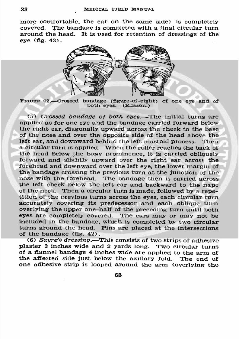
8/7/2019 FM 8-50 1940
http://slidepdf.com/reader/full/fm-8-50-1940 72/94
33 MEDICAL FIELD MANUAL
more comfortable, the ear on the same side) is completelycovered. The bandage is completed with a final circular turnaround the head. It is used for retention of dressings of the
eye (fig. 42).
FIGURE 42.-Crossed bandage (figure-of-eight) of one eye and ofboth eyes. (Eliason.)
(5) Crossed bandage of both eyes.-The initial turns areapplied as for one eye and the bandage carried forward belowthe right ear, diagonally upward across the cheek to the base
of the nose and over the opposite side of the head above theleft ear, and downward behind the left mastoid process. Thena circular turn is applied. When the roller reaches the back ofthe head below the bony prominence, it is carried obliquely
forward and slightly upward over the right ear across theforehead and downward over the left eye, the lower margin of
the bandage crossing the previous turn at the junction of thenose with the forehead. The bandage then is carried across
the left cheek below the left ear and backward to the napeof the neck. Then a circular turn is made, followed by a repe-tition of the previous turns across the eyes, each circular turnaccurately covering its predecessor and each oblique turnoverlying the upper one-half of the preceding turn until botheyes are completely covered. The ears may or may not beincluded in the bandage, which is completed by two circular
turns around the head. Pins are placed at the intersectionsof the bandage (fig. 42).
(6) Sayre's dressing.-This consists of two strips of adhesiveplaster 3 inches wide and 2 yards long. Two circular turnsof a flannel bandage 4 inches wide are applied to the arm of
the affected side just below the axillary fold. The end ofone adhesive strip is looped around the arm (overlying the
68
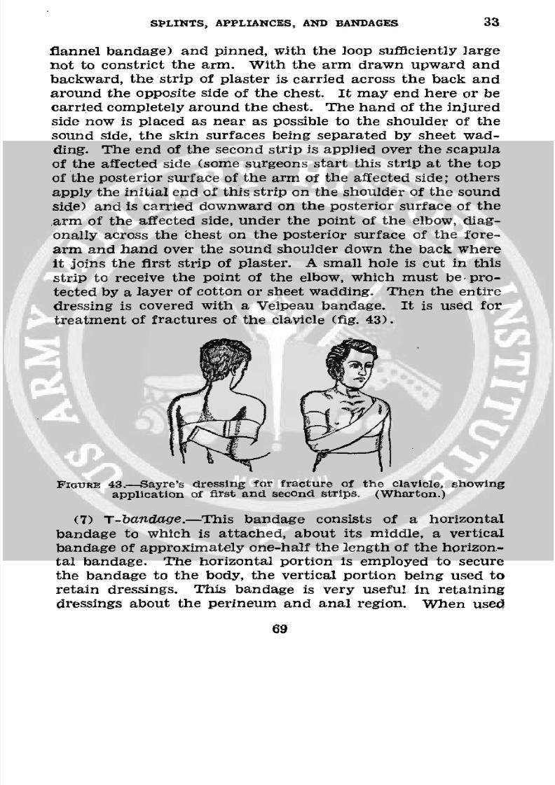
8/7/2019 FM 8-50 1940
http://slidepdf.com/reader/full/fm-8-50-1940 73/94
SPLINTS, APPLIANCES, AND BANDAGES 33
flannel bandage) and pinned, with the loop suffciently largenot to constrict the arm. With the arm drawn upward and
backward, the strip of plaster is carried across the back and
around the opposite side of the chest. It may end here or be
carried completely around the chest. The hand of the injuredside now is placed as near as possible to the shoulder of thesound side, the skin surfaces being separated by sheet wad-
ding. The end of the second strip is applied over the scapula
of the affected side (some surgeons start this strip at the top
of the posterior surface of the arm of the affected side; others
apply the initial end of this strip on the shoulder of the sound
side) and is carried downward on the posterior surface of the
arm of the affected side, under the point of the elbow, diag-
onally across the thest on the posterior surface of the fore-
arm and hand over the sound shoulder down the back where
it joins the first strip of plaster. A small hole is cut in this
strip to receive the point of the elbow, which must be pro-
tected by a layer of cotton or sheet wadding. Then the entiredressing is covered with a Velpeau bandage. It is used for
treatment of fractures of the clavicle (fig. 43).
FIOURE 43.-Sayre's dressing for fracture of the clavicle, showingapplication of first and second strips. (Wharton.)
(7) T-bandage.-This bandage consists of a horizontal
bandage to which is attached, about its middle, a vertical
bandage of approximately one-half the length of the horizon-tal bandage. The horizontal portion is employed to secure
the bandage to the body, the vertical portion being used toretain dressings. This bandage is very useful in retaining
dressings about the perineum and anal region. When used
69
8/7/2019 FM 8-50 1940
http://slidepdf.com/reader/full/fm-8-50-1940 74/94
33 MEDICAL FIELD MANUAL
for this purpose, the horizontal band is applied around theabdomen above the iliac crests in such manner that thevertical portion is placed exactly in the midline of the backdirectly over the spine. The vertical portion then is brought
forward between the thighs and secured to the horizontalportion in front of the abdomen. The vertical portion maybe split longitudinally to form two strips of equal width.
(8) Double T-bandage.-This differs from the T-bandagein having two vertical strips instead of only one. The hori-zontal portion may be of any desired width. It frequentlyis used for the retention of dressings of ,the chest, breast,and abdomen. When so employed, the two vertical strips arecarried over the shoulders from the back to the front andsecured by pins to the horizontal portion.
(9) Tailed bandage.-(a)The four-tailed bandage is madereadily by splitting a strip of muslin or other material ofthe desired width, lengthwise, within a few inches of the cen-ter of the strip. This provides a bandage with a body andfour tails.
(b) The many-tailed bandage is prepared in a similarmanner, by splitting the muslin or other material into severalstrips, having a sufficiently large area in the center for theretention of dressings, etc. The number of tails on each sideshould be the same.
(10) Plaster of paris bandage.-These bandages are pre-pared by impregnating the meshes of crinoline with plasterof paris of the extra calcined, dental variety. A strip of
crinoline about 3 or 4 inches wide and usually 4 or 5 yardslong, is placed on a table. Plaster of paris then is dustedupon the strip and evenly rubbed into the meshes of thefabric. A very satisfactory method of preparing this bandageis by constructing a wooden box, 12 inches long, 6 incheswide, and 3 inches deep, and at each end, just above thebottom of the box, cutting a slit 5 inches long and 1/8 to 1/4
inch wide. The end of the bandage is drawn into the boxthrough one slit across the bottom of the box and out of thebox through the other slit. A sufficient quantity of theplaster of paris to cover the bandage with a layer of powder1 inch deep is placed in the box. As the bandage is drawnthrough, plaster of paris is rubbed into the meshes with the
70
8/7/2019 FM 8-50 1940
http://slidepdf.com/reader/full/fm-8-50-1940 75/94
SPLINTS, APPLIANCES, AND BANDAGES 33
hand or preferably with a smooth piece of wood approxi-
mately 4 inches in length. The bandage may be loosely rolled
into a cylinder as it emerges from the box. If the bandages
are not to be used within a few hours, they should be wrapped
in paper to prevent absorption of moisture.
(a) Application.-The part to be encased in plaster of
paris should be Covered with a suitable bandage of soft mate-
rial, preferably flannel. The bony prominences should be
well protected with cotton. Care should be taken to remove
all creases in the dressing and bandage.
Two rolls of the plaster of paris bandage are placed in warm
water. When bubbles cease to arise from the bandage oneroll is removed from the water, the excess water being ex-pressed by grasping the roll at its two ends and exerting pres-
sure with the hands. This method prevents the loss of a con-
siderable amount of plaster through the ends of the roll.
NoTn.-As soon as a bandage is removed from the water replaceit with another bandage.
The bandage should be applied rapidly and evenly to the
limb. No special form of bandage is necessary as it is suffi-cient that the part be properly covered. The second bandage
is applied as soon as the first has been completed. During the
application of the bandage it should be rubbed with the handsin order to provide a smooth even surface. It also is desirable
to rub some loose plaster into the dressing. When the final
roller has been applied, the surface of the completed dressing
should be rubbed evenly with liquid plaster prepared by addi-tion of water to dry plaster until it has the consistency of
thick cream. In many cases, such as compound fractures,
it is frequently necessary to provide access to certain areas
of the encased limb. After the bandage has partially set a
"window" or trap may be cut in the bandage over the desired
area. Removal of a plaster of paris bandage may be accom-
plished with the aid of a plaster saw. If none is available, the:
plaster may be softened with a small amount of peroxide ofhydrogen, hydrochloric acid, or vinegar, and then may be
cut with a knife.(b) Uses.-This bandage is used for fixation of fractures;
ambulant treatment of fractures; fixation and treatment of
injuries and diseases of joints.
71
8/7/2019 FM 8-50 1940
http://slidepdf.com/reader/full/fm-8-50-1940 76/94
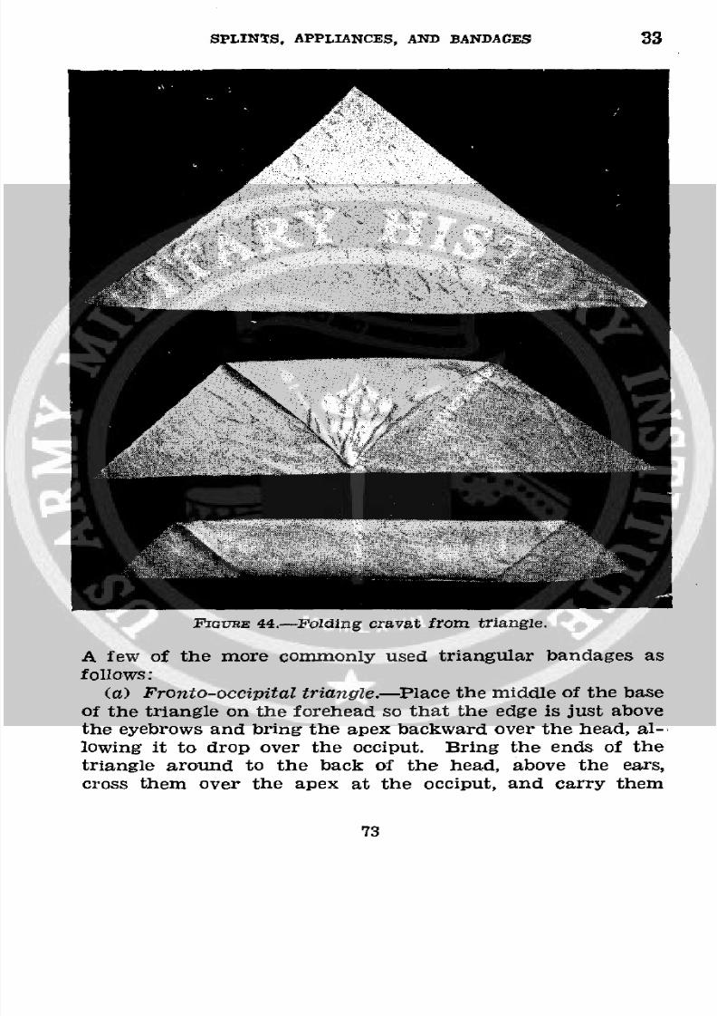
8/7/2019 FM 8-50 1940
http://slidepdf.com/reader/full/fm-8-50-1940 77/94
SPLINTS, APPLIANCES, AND BANDAGES 33
FtrvRE 44-Folding cravat from triangle.
A few of the more commonly used triangular bandages as
follows:
(a) Fronto-occipital riangle.-Placehe middle of the baseof the triangle on the forehead so that the edge is just above
the eyebrows and bring the apex backward over the head, al--
lowing it to drop over the occiput. Bring the ends of thetriangle around to the back of the head, above the ears,
cross them over the apex at the occiput, and carry them
73
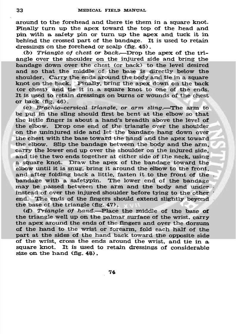
8/7/2019 FM 8-50 1940
http://slidepdf.com/reader/full/fm-8-50-1940 78/94
33 MEDICAL FIELD MANUAL
around to the forehead and there tie them in a square knot.
Finally turn up the apex toward the top of the head and
pin with a safety pin or turn up the apex and tuck it in
behind the crossed part of the bandage. It is used to retain
dressings on the forehead or scalp (fig. 45).(b) Triangle of chest or back.-Drop the apex of the tri-
angle over the shoulder on the injured side and bring thebandage down over the chest (or back) to the level desired
and so that the middle of the base is directly below theshoulder. Carry the ends around the body and tie in a square
knot on the back. Finally, bring the apex down on the back
(or chest) and tie it in a square knot to one of the ends.It is used to retain dressings on burns or wounds of the chest
or back (fig. 46).
(c) Brachio-cervieal triangle, or arm sling.-The arm to
be put in the sling should first be bent at the elbow so thatthe little finger is about a hand's breadth above the level ofthe elbow. Drop one end of the triangle over the shoulder
on the uninjured side and let the bandage hang down over
the chest with the base toward the hand and the apex towardthe elbow. Slip the bandage between the body and the arm,carry the lower end up over the shoulder on the injured side,
and tie the two ends together at either side of the neck, using
a square knot. Draw the apex of the bandage toward theelbow until it is snug, bring it around the elbow to the front,and after folding back a little, fasten it to the front of thebandage with a safetypin. The lower end of the bandagemay be passed between the arm and the body and under
instead of over the injured shoulder before tying to the other
end. The ends of the fingers should extend slightly beyondthe base of the triangle (fig. 47).
(Z) Triangle of hand.-Place the middle of the base ofthe triangle well up on the palmar surface of the wrist, carrythe apex around the ends of the fingers and over the dorsum
of the hand to the wrist or forearm, fold each half of thepart at the sides of the hand back toward the opposite side
of the wrist, cross the ends around the wrist, and tie in asquare knot. It is used to retain dressings of considerable
size on the hand (fig. 48),
74
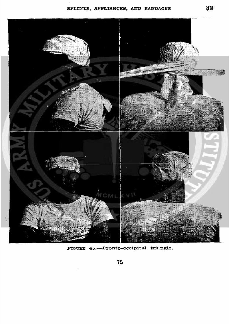
8/7/2019 FM 8-50 1940
http://slidepdf.com/reader/full/fm-8-50-1940 79/94
SPLINTS, APPLIANCES, AND BANDAGES 33
FIGURE 45.-fEonto-occipital triangle.
75
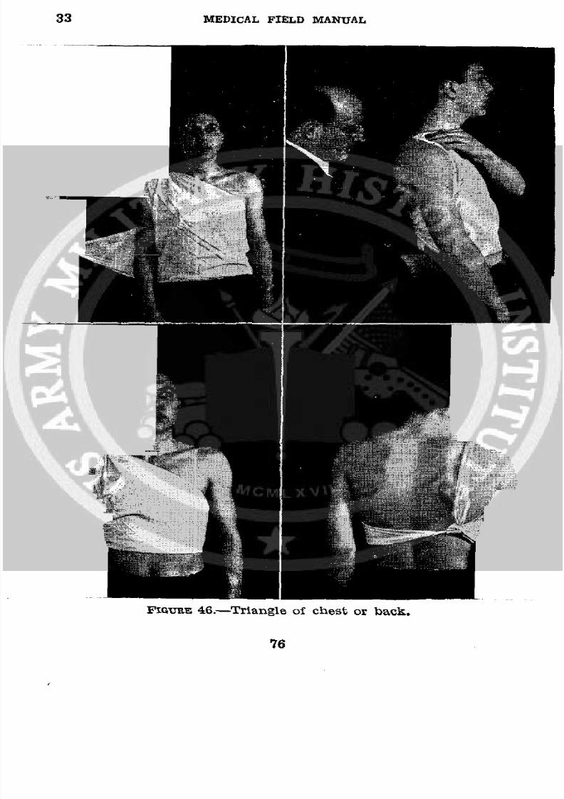
8/7/2019 FM 8-50 1940
http://slidepdf.com/reader/full/fm-8-50-1940 80/94
33 MEDICAL FIELD MANUAL
NI~
;l~iS
FmuE 46.-Triangle of chest or back.
76
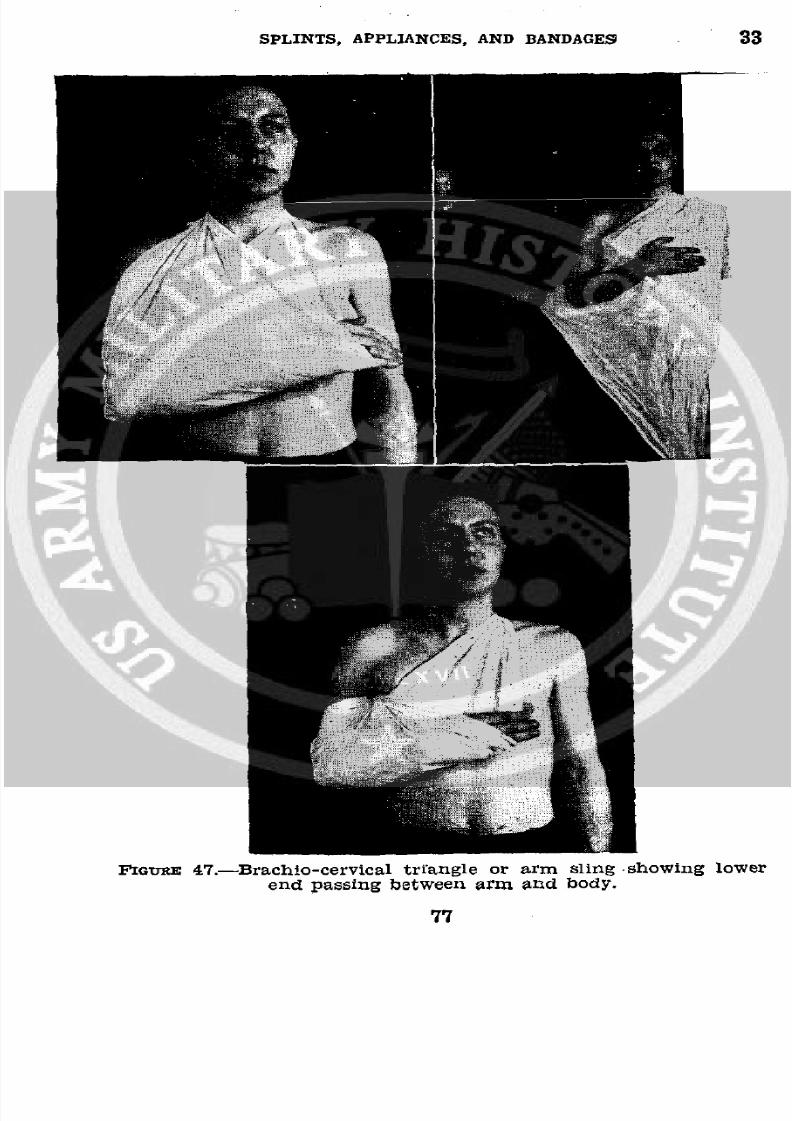
8/7/2019 FM 8-50 1940
http://slidepdf.com/reader/full/fm-8-50-1940 81/94
SPLINTS, APPLIANCES, AND BANDAGES 33
i__
FIGURE 47.-Brachio-cervical triangle or arm sling showing lower
end passing between arm and body.
77
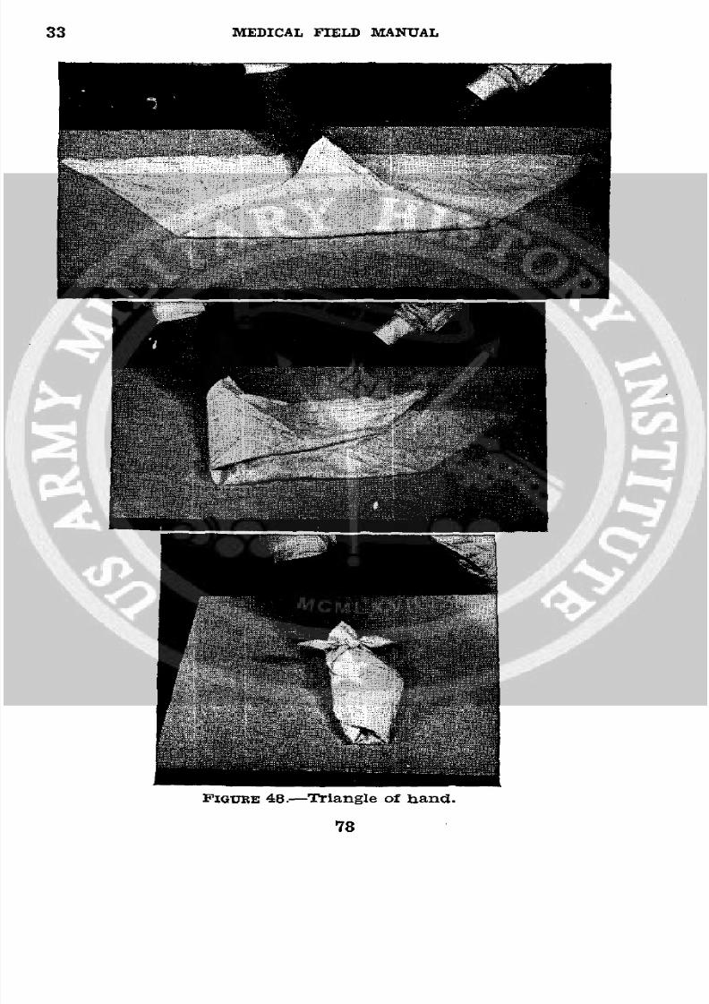
8/7/2019 FM 8-50 1940
http://slidepdf.com/reader/full/fm-8-50-1940 82/94
33 MEDICAL FIELD MANUAL
FIGURE 48.-Triangle of hand.
78
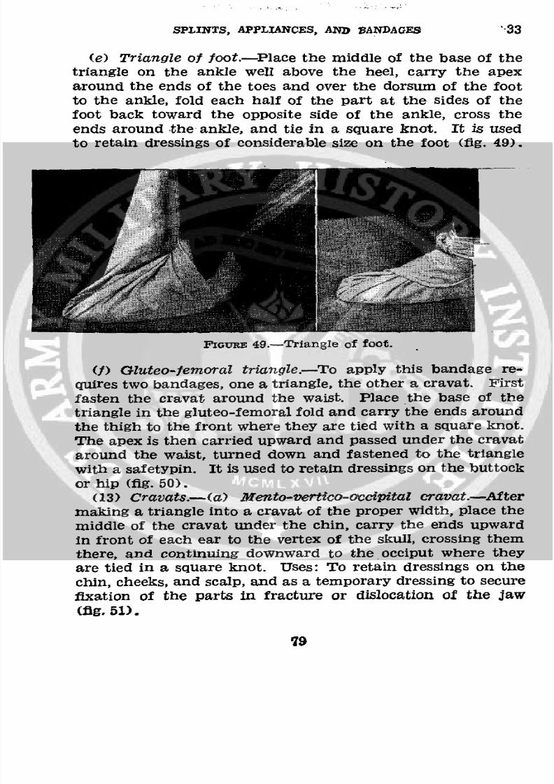
8/7/2019 FM 8-50 1940
http://slidepdf.com/reader/full/fm-8-50-1940 83/94
SPLINTS, APPLIANCES, AND BANDAGES '33
(e) Triangle of foot.-Place the middle of the base of the
triangle on the ankle well above the heel, carry the apex
around the ends of the toes and over the dorsum of the foot
tothe
ankle,fold each half of the part at the sides of the
foot back toward the opposite side of the ankle, cross theends around the ankle, and tie in a square knot. It is usedto retain dressings of considerable size on the foot (fig. 49).
FIGuRE 49.-Triangle of foot.
(f) Gluteo-femoral triangle.-To apply this bandage re-quires two bandages, one a triangle, the other a cravat. First
fasten the cravat around the waist. Place the base of thetriangle in the gluteo-femoral fold and carry the ends around
the thigh to the front where they are tied with a square knot.The apex is then carried upward and passed under the cravataround the waist, turned down and fastened to the trianglewith a safetypin. It is used to retain dressings on the buttockor hip (fig. 50).
(13) Cravats.-(a) Mento-vertico-occipital cravat.-After
making a triangle into a cravat of the proper width, place the
middle of the cravat under the chin, carry the ends upward
in front of each ear to the vertex of the skull, crossing themthere, and continuing downward to the occiput where theyare tied in a square knot. Uses: To retain dressings on the
chin, cheeks, and scalp, and as a temporary dressing to securefixation of the parts in fracture or dislocation of the jaw(fig, 51).
i9
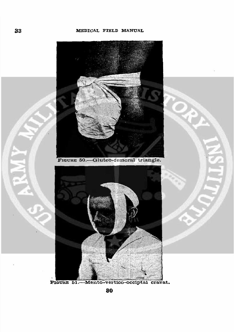
8/7/2019 FM 8-50 1940
http://slidepdf.com/reader/full/fm-8-50-1940 84/94
33 MEDICAL FIELD MANUAL
FIGURE 50.-Gluteo-femoral triangle.
zIGURE1.-Mento-vertico-occiptal cravat.
80
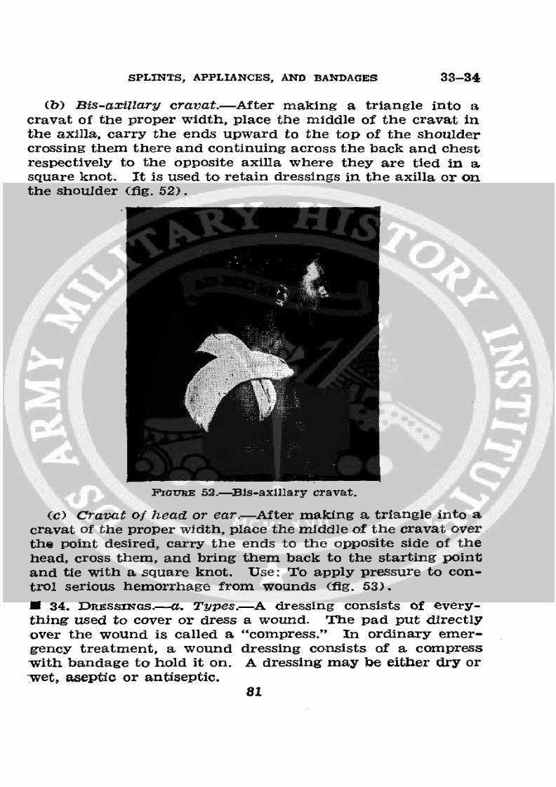
8/7/2019 FM 8-50 1940
http://slidepdf.com/reader/full/fm-8-50-1940 85/94
SPLINTS, APPLIANCES, AND BANDAGES 33-34
(b) Bis-axillary cravat.-After making a triangle into a.
cravat of the proper width, place the middle of the cravat in
the axilla, carry the ends upward to the top of the shoulder
crossing them there and continuing across the back and chest
respectively to the opposite axilla where they are tied in a
square knot. It is used to retain dressings in the axilla or on
the shoulder (fig. 52).
'ivGuE 52.--Bis-axillary cravat.
(C) Cravat of head or ear.-After making a, triangle into a
cravat of the proper width, place the middle of the cravat over
the point desired, carry the ends to the opposite side of thehead, cross them, and bring them back to the starting point
and tie with a square knot. Use: To apply pressure to con-
trol serious hemorrhage from wounds (fig. 53).* 34. DrEssINGs.-a. Types.-A dressing consists of every-thing used to cover or dress a wound. The pad put directly
over the wound is called a "compress." In ordinary emer-gency treatment, a wound dressing consists of a compress
with bandage to hold it on. A dressing may be either dry or
wet, aseptic or antiseptic.81
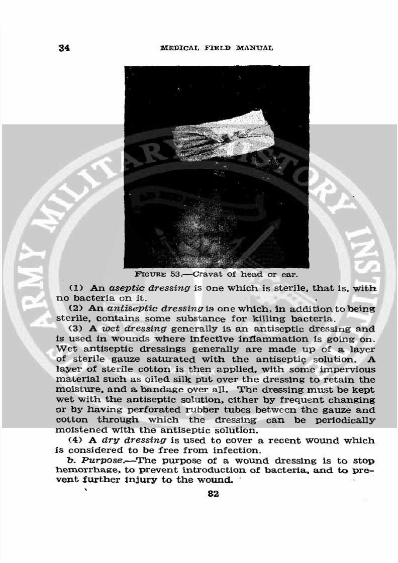
8/7/2019 FM 8-50 1940
http://slidepdf.com/reader/full/fm-8-50-1940 86/94
34 MEDICAL FIELD MANUAL
FIGURE 53.-Cravat of head or ear.
(1) An aseptic dressing is one which is sterile, that is, withno bacteria on it.
(2) An antisepticdressing s one which, in addition to beingsterile, contains some substance for killing bacteria.
(3) A wet dressing generally is an antiseptic dressing and
is used in wounds where infective inflammation is going on.Wet antiseptic dressings generally are made up of a layer
of sterile gauze saturated with the antiseptic solution. Alayer of sterile cotton is then applied, with some imperviousmaterial such as oiled silk put over the dressing to retain themoisture, and a bandage over all. The dressing must be keptwet with the antiseptic solution, either by frequent changingor by having perforated rubber tubes between the gauze and
cotton through which the dressing can be periodicallymoistened with the antiseptic solution.
(4) A dry dressing is used to cover a recent wound whichis considered to be free from infection.
b. Purpose.-The purpose of a wound dressing is to stophemorrhage, to prevent introduction of bacteria, and to pre-vent further injury to the wound.
82
8/7/2019 FM 8-50 1940
http://slidepdf.com/reader/full/fm-8-50-1940 87/94
SPLINTS, APPLIANCES, AND BANDAGES 34
c. Types in first-aidpacket.-The Army supplies two first-
aid packets, one small and one large, which are hermetically
sealed tin cans containing dry sterile dressings. (See figs.
54-57 incl.). All these dressings consist of a sterile gauze
compress with bandages attached.d. Preparationof wound for dressing.-(1) General.-Any
piece of cloth, such as gauze, cotton, linen, muslin, or a hand-
kerchief, provided it is rendered sterile, is suitable for a com-
press in case of emergency. The most vital point about ma-
terial used as a compress of a wound is that, before it is
applied to a wound, it should be rendered sterile. The part
of the dressing which is to come in contact with the woundmust not be touched with any part of the body or anything
else except sterile instruments before its application to thewound. In an emergency, material to be used in a wound
dressing may be sterilized by boiling it for 10 minutes.
(2) Procedures.-Whena patient can be brought under the
care of a medical officer in the near future, the procedure
necessary in the first-aid treatment in the case of ordinary
wounds is to stop the hemorrhage, treat the shock, and applya sterile dressing to the wound. If a medical officer is not
available, the wound must be further treated as described
below.
(a) In treating a freshly made wound, the following pro-
cedure is recommended:
1. Cleanse the hands as thoroughly as possible by a
thorough scrubbing with soap and hot water, fol-
lowed, if possible, by immersion in hot 1-2000bichloride of mercury solution and then 70 per-
cent alcohol.
2. Sterilize all instruments to be used in removing for-
eign bodies such as dirt, glass, splinters, or for
shoving the skin about the wounds.
3. If there is bleeding, arrest the hemorrhage.
4. If there is grease in or about the wound, remove itwith turpentine or gasoline.
5. Remove all foreign particles with sterile forceps.
6. Apply tincture of iodine to all parts of wound andthe skin about the wound for a distance of about
l/z inch beyond the wound edges. After the skin
83
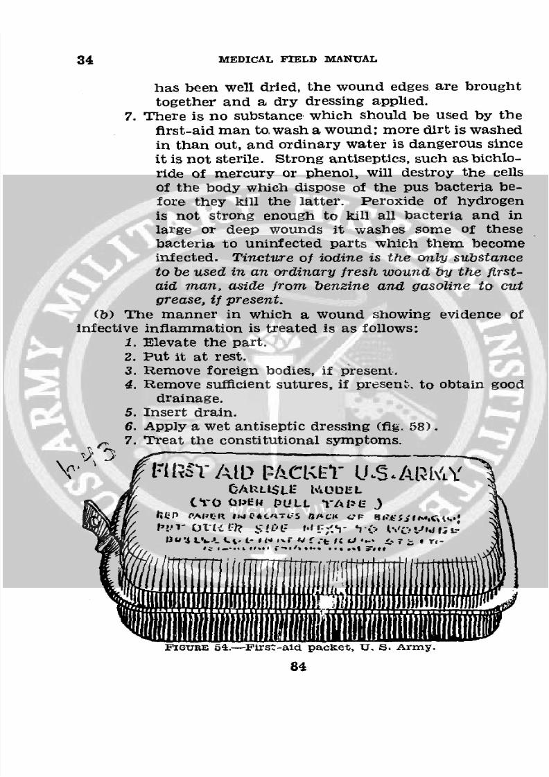
8/7/2019 FM 8-50 1940
http://slidepdf.com/reader/full/fm-8-50-1940 88/94
34 MEDICAL FIELD MANUAL
has been well dried, the wound edges are brought
together and a dry dressing applied.
7. There is no substance which should be used by the
first-aid man to wash a wound; more dirt is washedin than out, and ordinary water is dangerous sinceit is not sterile. Strong antiseptics, such as bichlo-ride of mercury or phenol, will destroy the cellsof the body which dispose of the pus bacteria be-fore they kill the latter. Peroxide of hydrogenis not strong enough to kill all bacteria and inlarge or deep wounds it washes some of these
bacteria to uninfected parts which them becomeinfected. Tincture of iodine is the only substance
to be used in an ordinary fresh wound by the first-
aid man, aside from benzine and gasoline to cut
grease, if present.
(b) The manner in which a wound showing evidence ofinfective inflammation is treated is as follows:
1. Elevate the part.
2. Put it at rest.3. Remove foreign bodies, if present,4. Remove sufficient sutures, if present. to obtain good
drainage.5. Insert drain.6. Apply a wet antiseptic dressing (fig. 58).7. Treat the constitutional symptoms.
Vll k,' ,T At.L)lCIE )~1-S (~tWOA'LZLE LrOUEL
S f(aO OPER PULL 'I-AlzE)
S11111 1 i i l UI A !
FIGURE 654-First-aid packet, U. S. Army.
84
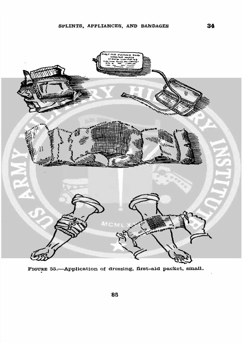
8/7/2019 FM 8-50 1940
http://slidepdf.com/reader/full/fm-8-50-1940 89/94
SPLINTS, APPLIANCES, AND BANDAGES 34
FIGURE 55.-Application of dressing, first-aid packet, small.
85
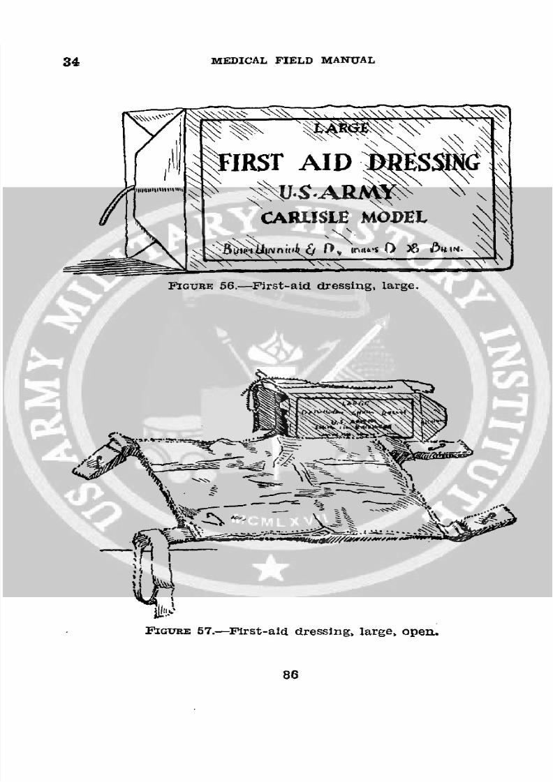
8/7/2019 FM 8-50 1940
http://slidepdf.com/reader/full/fm-8-50-1940 90/94
34 MEDICAL FIELD MANUAL
\\\\\\>'Z\\\
IRST AID
CARLISLE MODEL
FIGURE 56.-First-aid dressing, large.
4.B
FIGURE 57.-First-aid dressing, large, open.
86
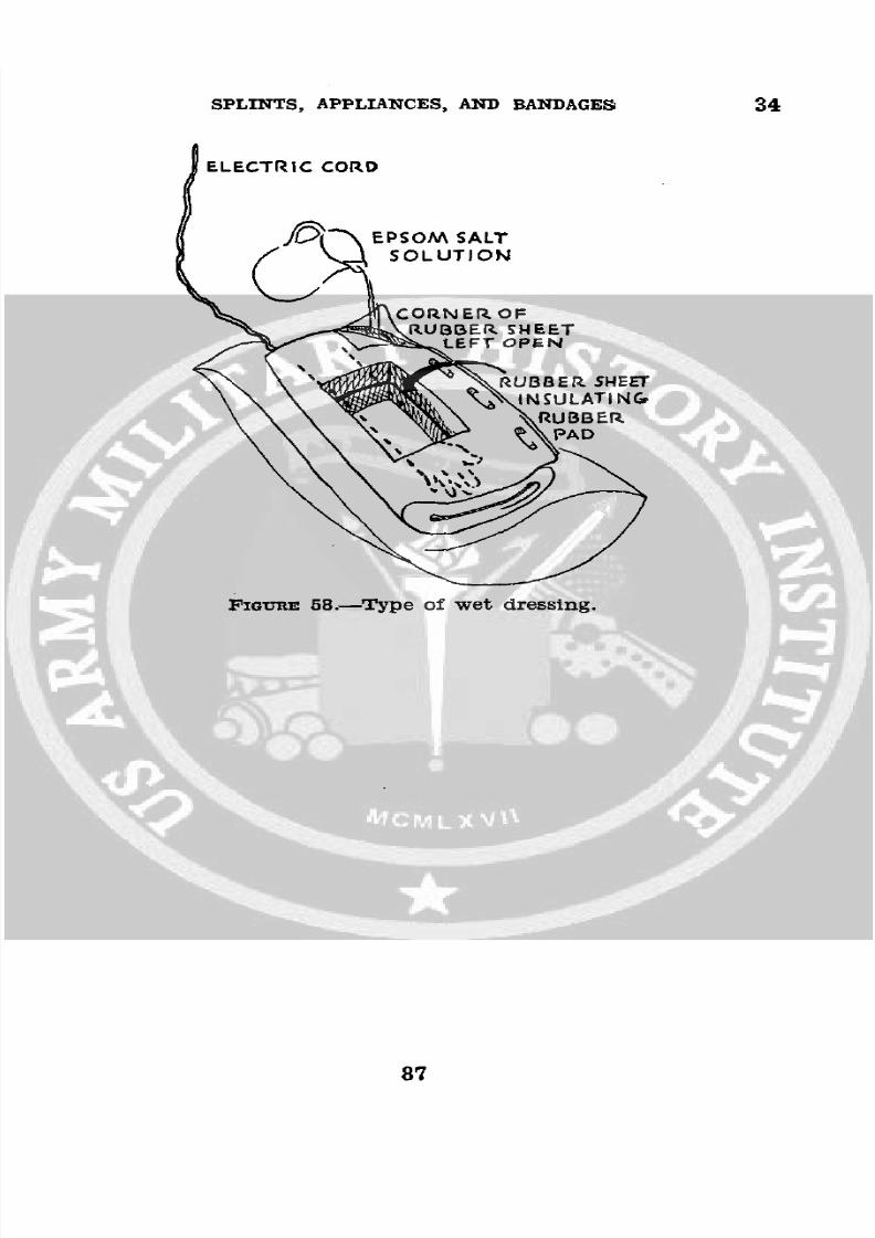
8/7/2019 FM 8-50 1940
http://slidepdf.com/reader/full/fm-8-50-1940 91/94
SPLINTS, APPLIANCES, AND BANDAGES 34
ELECTRIC CORD
A/> EPSOM SALT
C, S O L U T I O N
v. A~JCORN ER OF~. _., RUBBER SHEET
EFT OPEN
X ';', 1,,N SULATINGRUBBER
FIGT-RE 58.-Type of wet dressing.
87
8/7/2019 FM 8-50 1940
http://slidepdf.com/reader/full/fm-8-50-1940 92/94
APPENDIX
BIBLIOGRAPHY
Figures 16 and 17. Courtesy of The Tower Company, Inc.,
Seattle, Wash.
Figures 27 and 28. Courtesy of Dr. W. Gayle Crutchfield inJ. Bone and Joint Surgery, July 1938.
88
8/7/2019 FM 8-50 1940
http://slidepdf.com/reader/full/fm-8-50-1940 93/94
INDEX
Apparatus: Paragraph PageExtension, Steinmann__-______--__._____ ..6 29Wire ---___-- ______________________________ 18 30
Attachments, Pierson-_________ ________________ 20 32
Balkan frame __--____________----- _ 14 22
Bandages and dressings----___-______-- ___--_.-- 1, S31 1, 52Application and use----_____________________ 33 55Bandaging, rules for --_---___-_____-__-___--___ 32 54
Casts:Body, hyperextension, pipe frame and ham-
mock for_-----------_---_--------- -_____ 28 46Plaster ---------------------------- ___--___ 27 45
Dislocations, cervical spine____-_________________ 30 50Dressings and bandages----------------- __ 1,31,32,34 1,52,
54,81
Fractures:Cervical spine ------------------------------ 30 50Clavicle, T-splint for------------------_____. 23 38Compression, spine --_______________________ 29 49Definitive treatment of ____________________ 13 21Major, lower extremities, immobilization for
transportation -_------------------------- 6 9Proximal and distal, skeletal fixation___-____ 19 80Spinal, emergency treatment and transporta-
tion -_---------------------------------- 7 12Splinting for transportation --_______-______ 2 2
Hammock and pipe frame for hyperextension bodycast ----------------------------------------- 20 46
Immobilization for transportation, major lowerextremity fractures _------------------------- 6 9
Pierson attachment -----------------------.---- 20 32Pipe frame and hammock for hyperextension body
cast --_------------------------------------- 28 46Plaster casts ________________------------- --- - 27 45Plaster of paris _--------------------_----------- 26 44
Shock, traumatic, prevention and early treatment_ 11 18Skeletal fixation, proximal and distal fractures___ 19 30Skeletal suspension and traction________________ 17 29Skin traction____________------------------ 15 27Splinting fractures for transportation --- __----- 2 2
89
8/7/2019 FM 8-50 1940
http://slidepdf.com/reader/full/fm-8-50-1940 94/94
INDEX
Splints: Paragraph PageAeroplane or abduction _-_________________ 24 40Basswood ------__-------___________________ 10,25 18, 42Cabot ---------------------- ________.___--_ 21 35Leg and thigh, half-ring, hinged, army-___-- 3 2Straps, adjustable traction_-___-. ____________- 4 4Supports and footrests for_--________________ 5 4
T, for fractured clavicle_______________-_____ 23 38Thomas, arm-hinged ____________-__________ 9 15Wire ladder------------------_--_---__-- __-- 8 14Wrist, aluminum cock-up ---__-_-_._-__-__ 22 37
Splints, appliances, and bandages, .purpose andscope of manual on---------------.---- _ _____ 1 1
Steinmann extension apparatus_________________ 16 29
Traction and suspension, skeletal________________ 17 29
O