Meetup 25/4/2016 - Functionele IoT architectuur Antwerpen v2
Aalto-yliopisto, Sähkötekniikan korkeakoulu
ELEC-D0301 Protopaja
2018
Final Report
Project #09 Aalto-Tuxera IoT
Date: 31.8.2018
Page 1 of 30

Alexey Ganzhinov Thao Nguyen
Veli-Matti Rantanen Teemu Vierros
Page 2 of 30
Information Page
Students
Alexey Ganzhinov (#649830) Thao Nguyen (#588506) Veli-Matti Rantanen (#480798) Teemu Vierros (#606268)
Project Manager
Veli-Matti Rantanen
Sponsoring Company
Tuxera Oy
Starting Date
4.6.2018
Submitted Date
31.8.2018
Page 3 of 30
Tiivistelmä Projektin tavoitteena on tuottaa järjestelmä, joka sallii tarkoitusta varten suunnitellun mittalaitteen lähettämän datan visualisoinnin etänä yleisissä verkkoselaimissa. Tähän mennessä laitteesta on toteutettu BMD-340-A-R-sirua käyttävä CAD-malli, joka lähettää dataa BLE mainoksina (tätä kutsutaan myös nimellä “beacon”). Laitetta varten on jo kirjoitettu koodia käyttämällä hyväksi erilaisia prototyypitysalustoja. Siru lukee anturidataa I²C-väylän avulla.
Tällä hetkellä laitteen keräämä data lähetetään sen enempää muokkaamatta lähellä oleville “gateway”-laitteille, jotka sitten keräävät dataa useammasta laitteesta ja lähettävät sitä edelleen palvelimelle. Palvelin kirjaa lähetyksen, mutta ei muuten käsittele saapunutta dataa. Palvelin on kykeneväinen suoratoistamaan lähes mitä tahansa visualisoitavaa dataa asiakasohjelmille.
Page 4 of 30
Abstract The goal of the project is to produce a pipeline that will allow the viewing of sensor data from a purpose-built sensor board remotely from common web browsers. So far, we have built an initial CAD model of the sensor board utilizing Rigado’s BMD-340-A-R chip which is capable of broadcasting data over Bluetooth Low-Energy advertisements, also known as a beacon. We’ve also programmed some firmware for this device by using breakout boards and development kits to interface with various sensors over an I²C bus.
As-is, the data collected by the device is broadcasted in a non-specific format to a nearby gateway, that then relays that data directly to the web server where the delivery will be logged but otherwise the data is ignored. The web server is capable of streaming arbitrary data to clients, and the implementation of the rest of the pipeline should be relatively simple.
Page 5 of 30
Table of Contents
Tiivistelmä 4
Abstract 5
Table of Contents 6
1. Introduction 8
2. Objective 8
3. Hardware 8
3.1. Schematic 9
3.2 Routing 10
3.3 Case Design 11
3.4 Other 13
4. Firmware 13
4.1. Development environment 13
4.2. Program Structure 13
4.3. Communicating with the sensors 15
4.4. Packets & Security 16
4.5. Broadcasting with Bluetooth beacons 17
5. Web Service 17
5.1. Server 18
5.1.1. Data Processing 18
5.1.2. Storage & Security 18
5.1.3. Data Stream 19
5.2. Visualization Client 19
6. Project Self-Assessment 19
6.1. Objectives 19
6.2. Schedule 20
Page 6 of 30
6.3. Risk Analysis 20
7. Discussion and Conclusions 21
7.1. Alexey Ganzhinov 21
7.2. Thao Nguyen 21
7.3. Veli-Matti Rantanen 21
7.4. Teemu Vierros 21
Appendices 21
List of Appendices 21
Appendix A. Device Schematic 22
Appendix B. Server Diagram 24
References 26
Page 7 of 30
1. Introduction The Internet of Things is a hot topic in the modern world, where devices that traditionally have had very little to do with connectivity, are becoming increasingly more connected with each other. In this project, we design and fabricate our own device capable of recording real-world data and delivering it to an IoT gateway, as well as a web service capable of processing and visualizing that data.
2. Objective The main objective of the project was to develop a functional pipeline that records, aggregates and visualizes sensor data. The parts that we designed and developed were the Bluetooth low-energy sensor board and its firmware, along with a protocol for transmitting the data over Bluetooth low-energy beacons to the gateway and from the gateway to our node.js server backend. The gateway was provided by Tuxera, although one could easily design their own, or program an existing Bluetooth low-energy device to fulfill the function.
Finally, the server was to be capable of reproducing the data for web clients running in the most common web browsers, namely Mozilla Firefox and Google Chrome, as well as common smartphone browsers.
Page 8 of 30
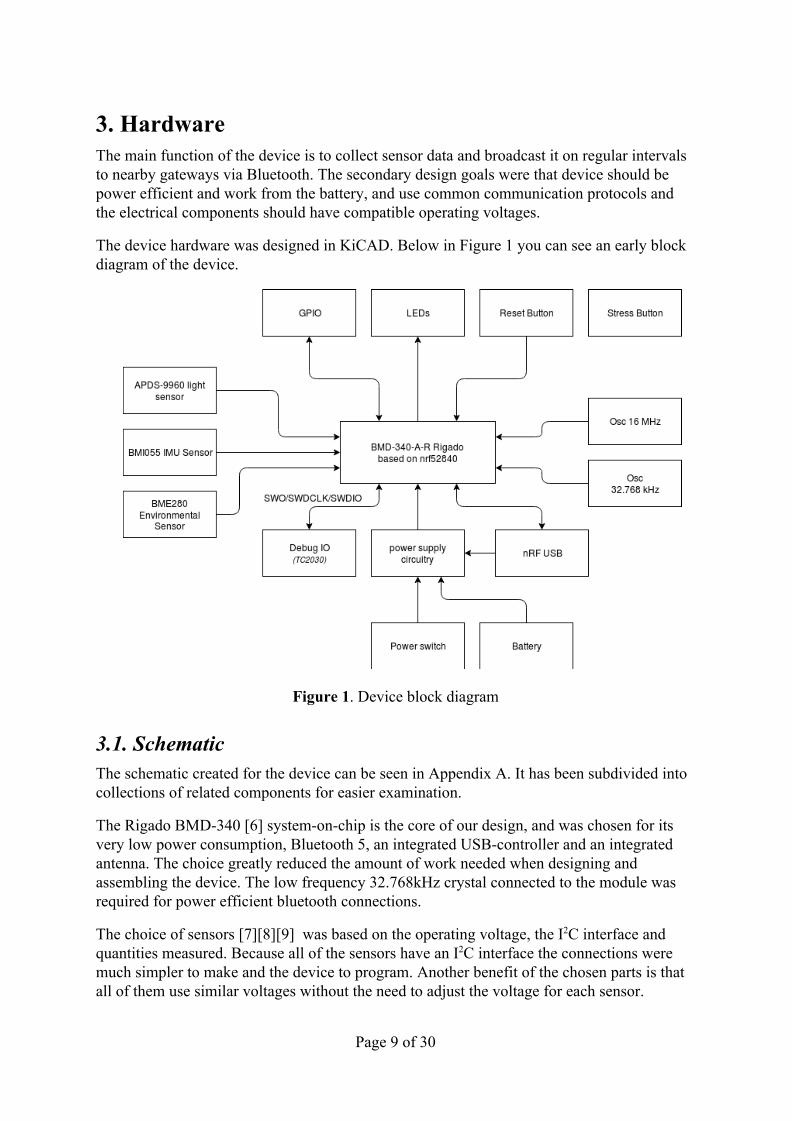
3. Hardware The main function of the device is to collect sensor data and broadcast it on regular intervals to nearby gateways via Bluetooth. The secondary design goals were that device should be power efficient and work from the battery, and use common communication protocols and the electrical components should have compatible operating voltages.
The device hardware was designed in KiCAD. Below in Figure 1 you can see an early block diagram of the device.
Figure 1. Device block diagram
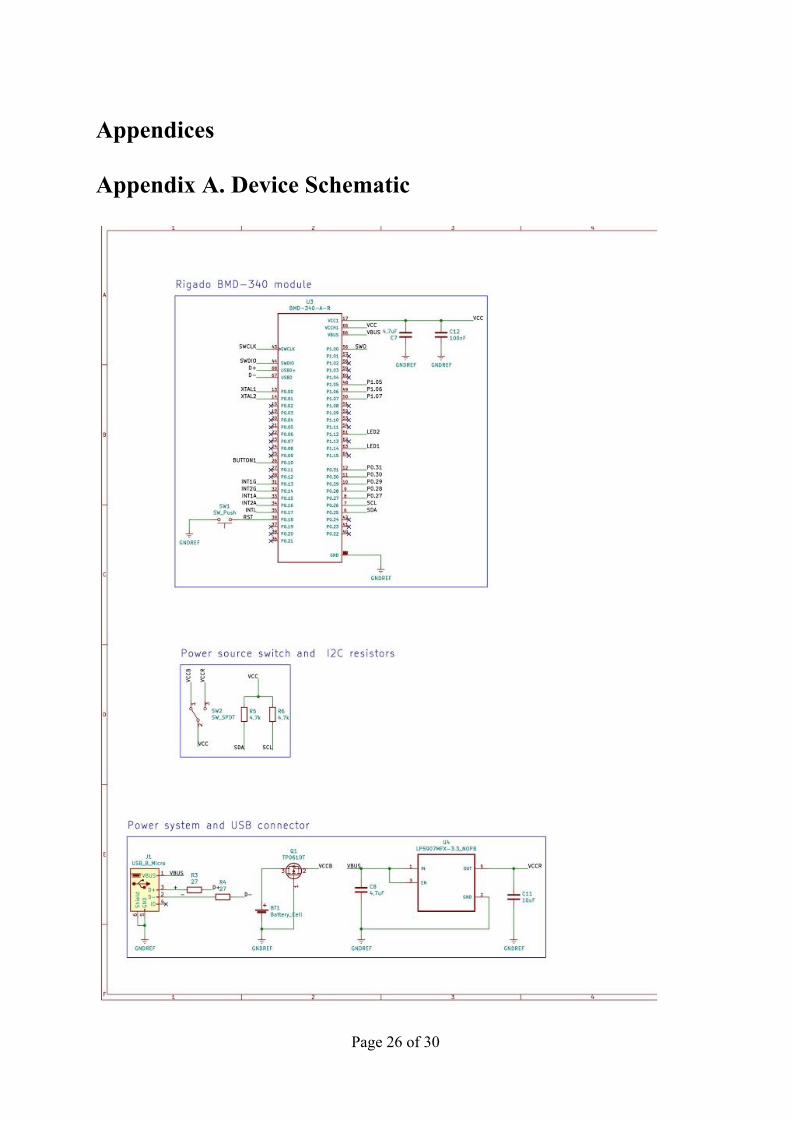
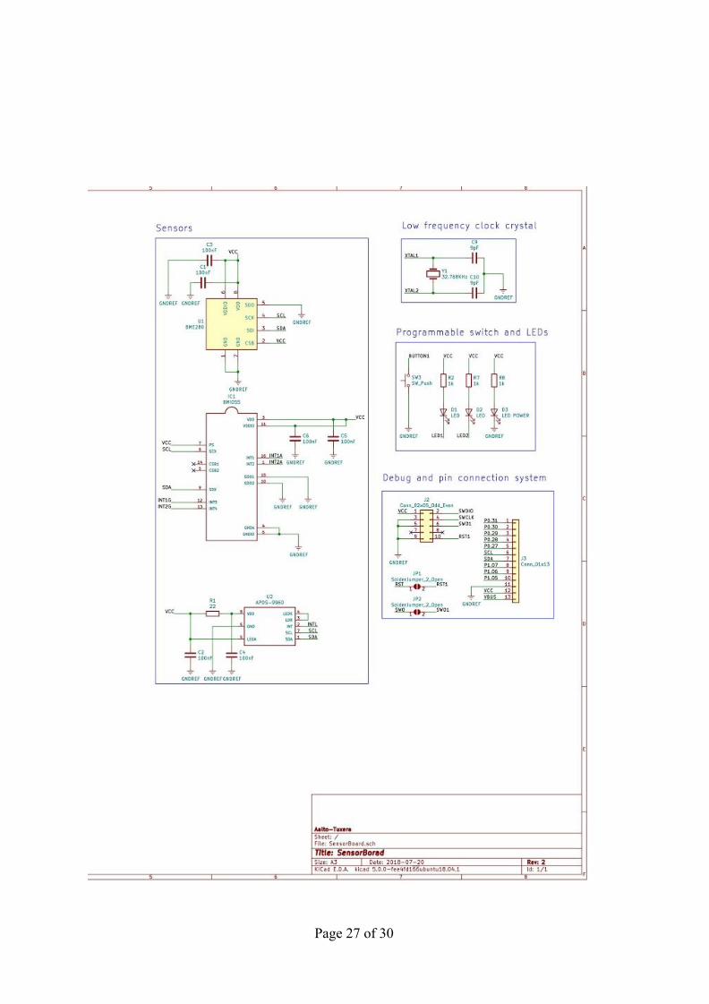
3.1. Schematic The schematic created for the device can be seen in Appendix A. It has been subdivided into collections of related components for easier examination.
The Rigado BMD-340 [6] system-on-chip is the core of our design, and was chosen for its very low power consumption, Bluetooth 5, an integrated USB-controller and an integrated antenna. The choice greatly reduced the amount of work needed when designing and assembling the device. The low frequency 32.768kHz crystal connected to the module was required for power efficient bluetooth connections.
The choice of sensors [7][8][9] was based on the operating voltage, the I2C interface and quantities measured. Because all of the sensors have an I2C interface the connections were much simpler to make and the device to program. Another benefit of the chosen parts is that all of them use similar voltages without the need to adjust the voltage for each sensor.
Page 9 of 30
The power system architecture is designed around the need to have two choices by which the device can be powered: USB or battery. The incompatibility is solved by connecting USB power to a linear regulator that drops the voltage from 5V to 3.3V. Then it was connected to a switch, along with the battery, to make choosing between the power sources easy. Our design also has a reverse connection protection MOSFET for the battery so that if you insert battery the wrong way nothing happens.
The debug port that we used is a common 10-pin 1.27mm SWD programming connector that is also used on many ARM Cortex development kits. This port has two pins with solder bridges that can be connected if needed. Schematic also has a 1x13 header for broken out pins of the BMD-340 module for future development if needed, compatible with a standard breadboard.
The schematic also features a reset button, one programmable button and two programmable LEDs. These can be programmed to, for example, toggle power saving mode on and off and to indicate which mode is currently on. There is one power indicator LED that is constantly on when the board has power.
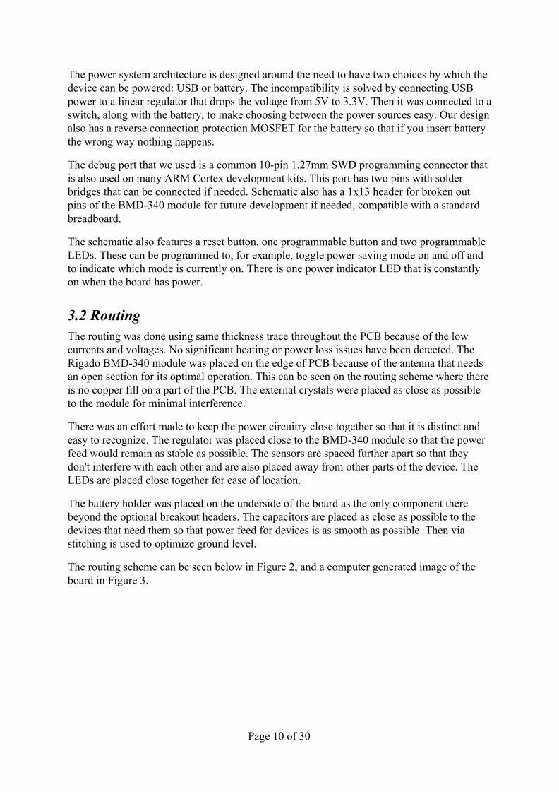
3.2 Routing The routing was done using same thickness trace throughout the PCB because of the low currents and voltages. No significant heating or power loss issues have been detected. The Rigado BMD-340 module was placed on the edge of PCB because of the antenna that needs an open section for its optimal operation. This can be seen on the routing scheme where there is no copper fill on a part of the PCB. The external crystals were placed as close as possible to the module for minimal interference.
There was an effort made to keep the power circuitry close together so that it is distinct and easy to recognize. The regulator was placed close to the BMD-340 module so that the power feed would remain as stable as possible. The sensors are spaced further apart so that they don't interfere with each other and are also placed away from other parts of the device. The LEDs are placed close together for ease of location.
The battery holder was placed on the underside of the board as the only component there beyond the optional breakout headers. The capacitors are placed as close as possible to the devices that need them so that power feed for devices is as smooth as possible. Then via stitching is used to optimize ground level.
The routing scheme can be seen below in Figure 2, and a computer generated image of the board in Figure 3.
Page 10 of 30
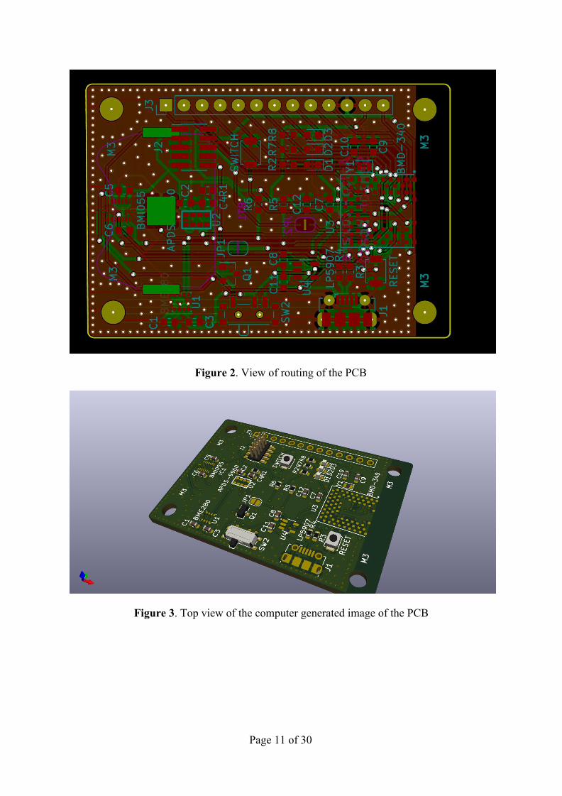
Figure 2. View of routing of the PCB
Figure 3. Top view of the computer generated image of the PCB
Page 11 of 30
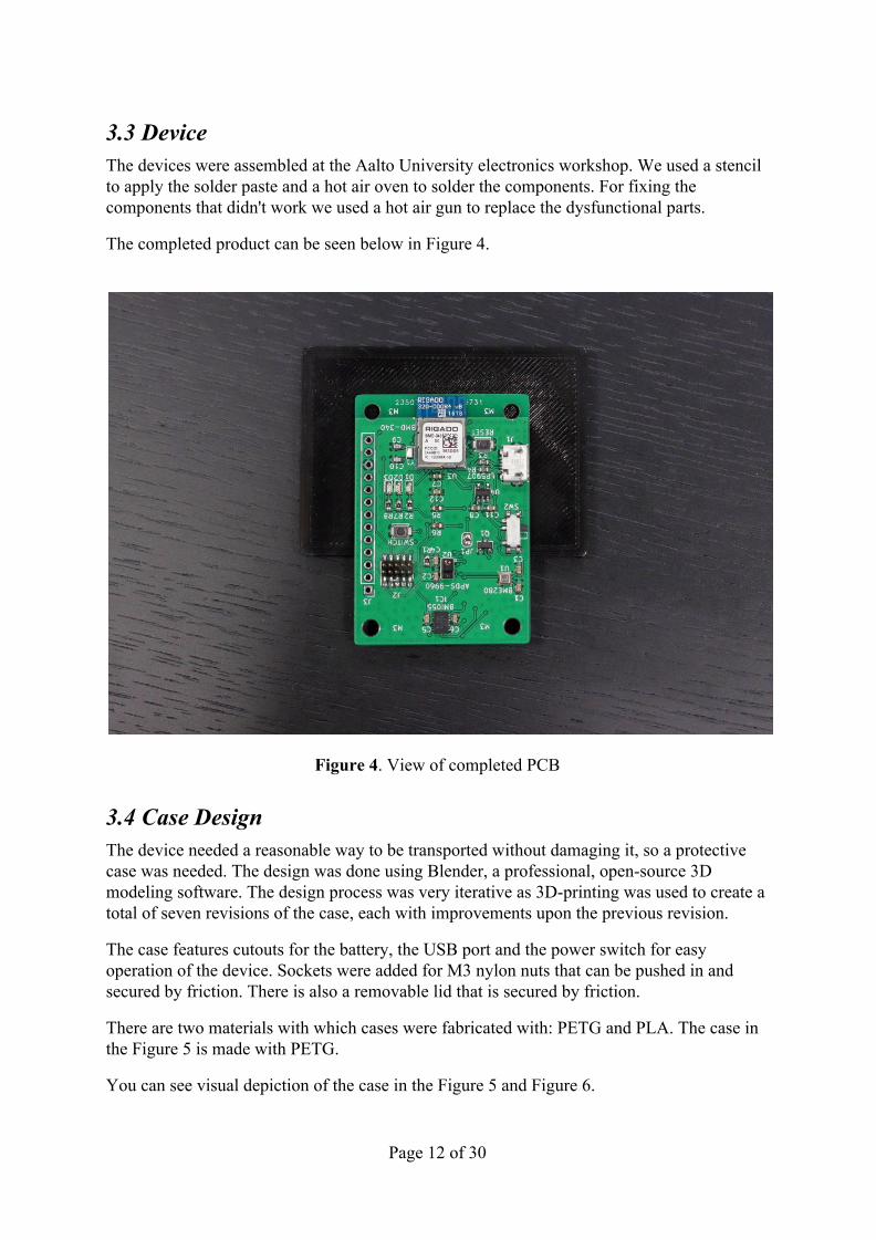
3.3 Device The devices were assembled at the Aalto University electronics workshop. We used a stencil to apply the solder paste and a hot air oven to solder the components. For fixing the components that didn't work we used a hot air gun to replace the dysfunctional parts.
The completed product can be seen below in Figure 4.
Figure 4. View of completed PCB
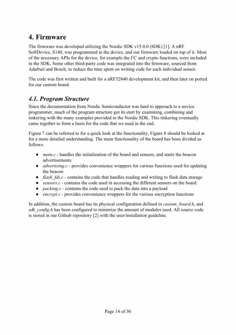
3.4 Case Design The device needed a reasonable way to be transported without damaging it, so a protective case was needed. The design was done using Blender, a professional, open-source 3D modeling software. The design process was very iterative as 3D-printing was used to create a total of seven revisions of the case, each with improvements upon the previous revision.
The case features cutouts for the battery, the USB port and the power switch for easy operation of the device. Sockets were added for M3 nylon nuts that can be pushed in and secured by friction. There is also a removable lid that is secured by friction.
There are two materials with which cases were fabricated with: PETG and PLA. The case in the Figure 5 is made with PETG.
You can see visual depiction of the case in the Figure 5 and Figure 6.
Page 12 of 30
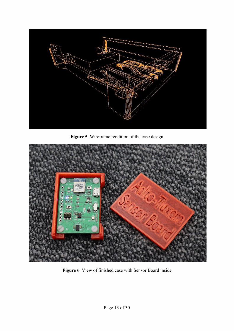
Figure 5. Wireframe rendition of the case design
Figure 6. View of finished case with Sensor Board inside
Page 13 of 30
4. Firmware The firmware was developed utilizing the Nordic SDK v15.0.0 (SDK) [1]. A nRF SoftDevice, S140, was programmed in the device, and our firmware loaded on top of it. Most of the necessary APIs for the device, for example the I2C and crypto functions, were included in the SDK. Some other third-party code was integrated into the firmware, sourced from Adafruit and Bosch, to reduce the time spent on writing code for each individual sensor.
The code was first written and built for a nRF52840 development kit, and then later on ported for our custom board.
4.1. Program Structure Since the documentation from Nordic Semiconductor was hard to approach to a novice programmer, much of the program structure got its start by examining, combining and tinkering with the many examples provided in the Nordic SDK. This tinkering eventually came together to form a basis for the code that we used in the end.
Figure 7 can be referred to for a quick look at the functionality, Figure 8 should be looked at for a more detailed understanding. The main functionality of the board has been divided as follows.
● main.c - handles the initialization of the board and sensors, and starts the beacon advertisements
● advertising.c - provides convenience wrappers for various functions used for updating the beacon
● flash_fds.c - contains the code that handles reading and writing to flash data storage ● sensors.c - contains the code used in accessing the different sensors on the board ● packing.c - contains the code used to pack the data into a payload ● encrypt.c - provides convenience wrappers for the various encryption functions
In addition, the custom board has its physical configuration defined in custom_board.h, and sdk_config.h has been configured to minimize the amount of modules used. All source code is stored in our Github repository [2] with the user/installation guideline.
Page 14 of 30
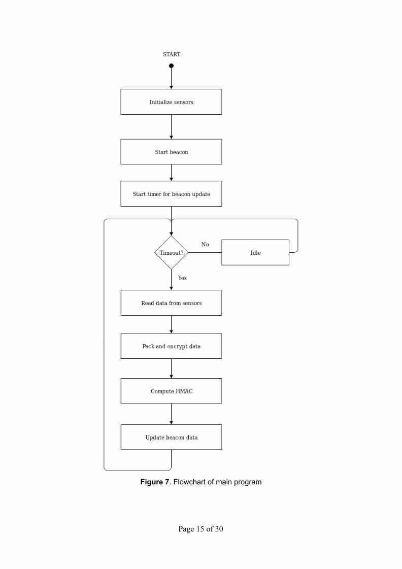
Figure 7. Flowchart of main program
Page 15 of 30
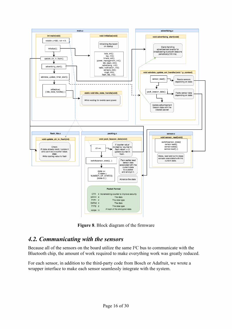
Figure 8. Block diagram of the firmware
4.2. Communicating with the sensors Because all of the sensors on the board utilize the same I²C bus to communicate with the Bluetooth chip, the amount of work required to make everything work was greatly reduced.
For each sensor, in addition to the third-party code from Bosch or Adafruit, we wrote a wrapper interface to make each sensor seamlessly integrate with the system.
Page 16 of 30
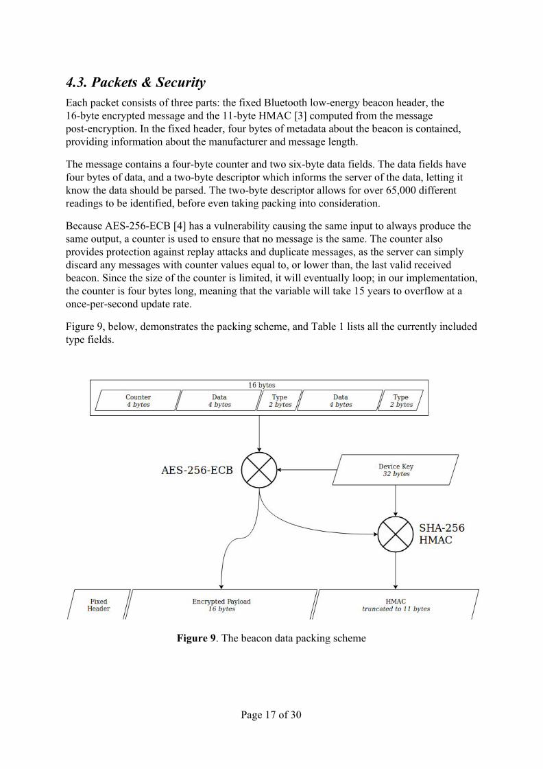
4.3. Packets & Security Each packet consists of three parts: the fixed Bluetooth low-energy beacon header, the 16-byte encrypted message and the 11-byte HMAC [3] computed from the message post-encryption. In the fixed header, four bytes of metadata about the beacon is contained, providing information about the manufacturer and message length.
The message contains a four-byte counter and two six-byte data fields. The data fields have four bytes of data, and a two-byte descriptor which informs the server of the data, letting it know the data should be parsed. The two-byte descriptor allows for over 65,000 different readings to be identified, before even taking packing into consideration.
Because AES-256-ECB [4] has a vulnerability causing the same input to always produce the same output, a counter is used to ensure that no message is the same. The counter also provides protection against replay attacks and duplicate messages, as the server can simply discard any messages with counter values equal to, or lower than, the last valid received beacon. Since the size of the counter is limited, it will eventually loop; in our implementation, the counter is four bytes long, meaning that the variable will take 15 years to overflow at a once-per-second update rate.
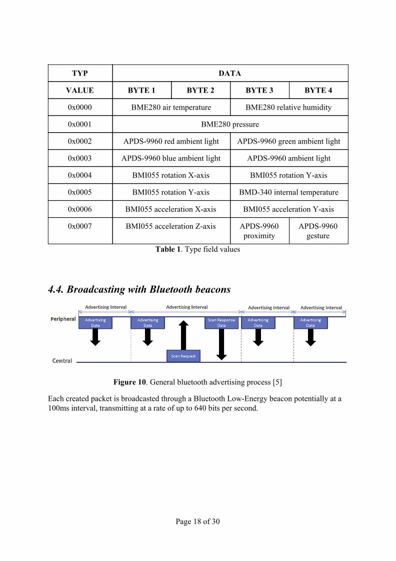
Figure 9, below, demonstrates the packing scheme, and Table 1 lists all the currently included type fields.
Figure 9. The beacon data packing scheme
Page 17 of 30
TYP DATA
VALUE BYTE 1 BYTE 2 BYTE 3 BYTE 4
0x0000 BME280 air temperature BME280 relative humidity
0x0001 BME280 pressure
0x0002 APDS-9960 red ambient light APDS-9960 green ambient light
0x0003 APDS-9960 blue ambient light APDS-9960 ambient light
0x0004 BMI055 rotation X-axis BMI055 rotation Y-axis
0x0005 BMI055 rotation Y-axis BMD-340 internal temperature
0x0006 BMI055 acceleration X-axis BMI055 acceleration Y-axis
0x0007 BMI055 acceleration Z-axis APDS-9960 proximity
APDS-9960 gesture
Table 1. Type field values
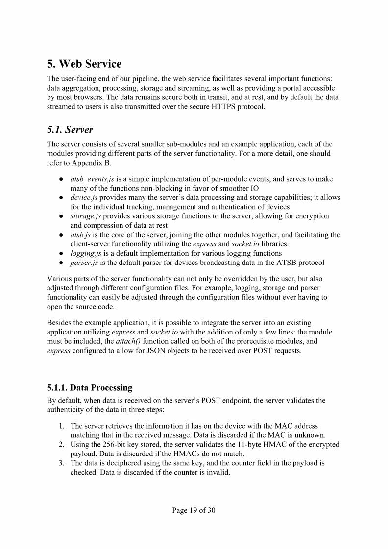
4.4. Broadcasting with Bluetooth beacons
Figure 10. General bluetooth advertising process [5]
Each created packet is broadcasted through a Bluetooth Low-Energy beacon potentially at a 100ms interval, transmitting at a rate of up to 640 bits per second.
Page 18 of 30
5. Web Service The user-facing end of our pipeline, the web service facilitates several important functions: data aggregation, processing, storage and streaming, as well as providing a portal accessible by most browsers. The data remains secure both in transit, and at rest, and by default the data streamed to users is also transmitted over the secure HTTPS protocol.
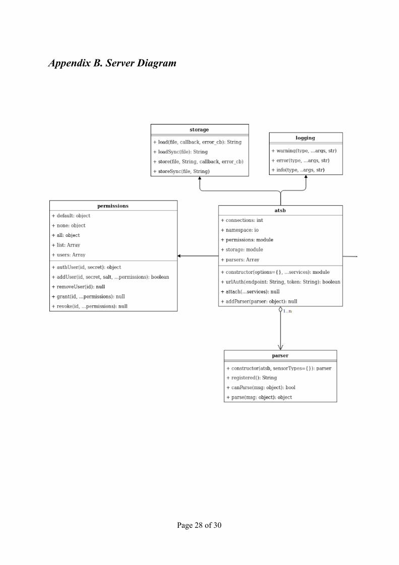
5.1. Server The server consists of several smaller sub-modules and an example application, each of the modules providing different parts of the server functionality. For a more detail, one should refer to Appendix B.
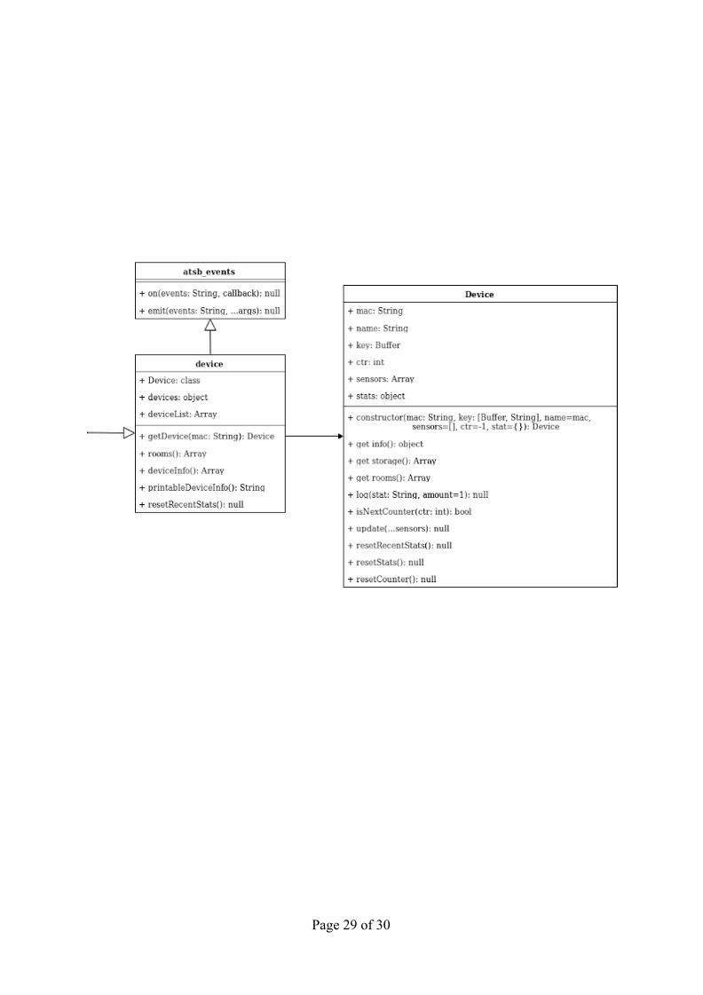
● atsb_events.js is a simple implementation of per-module events, and serves to make many of the functions non-blocking in favor of smoother IO
● device.js provides many the server’s data processing and storage capabilities; it allows for the individual tracking, management and authentication of devices
● storage.js provides various storage functions to the server, allowing for encryption and compression of data at rest
● atsb.js is the core of the server, joining the other modules together, and facilitating the client-server functionality utilizing the express and socket.io libraries.
● logging.js is a default implementation for various logging functions ● parser.js is the default parser for devices broadcasting data in the ATSB protocol
Various parts of the server functionality can not only be overridden by the user, but also adjusted through different configuration files. For example, logging, storage and parser functionality can easily be adjusted through the configuration files without ever having to open the source code.
Besides the example application, it is possible to integrate the server into an existing application utilizing express and socket.io with the addition of only a few lines: the module must be included, the attach() function called on both of the prerequisite modules, and express configured to allow for JSON objects to be received over POST requests.
5.1.1. Data Processing By default, when data is received on the server’s POST endpoint, the server validates the authenticity of the data in three steps:
1. The server retrieves the information it has on the device with the MAC address matching that in the received message. Data is discarded if the MAC is unknown.
2. Using the 256-bit key stored, the server validates the 11-byte HMAC of the encrypted payload. Data is discarded if the HMACs do not match.
3. The data is deciphered using the same key, and the counter field in the payload is checked. Data is discarded if the counter is invalid.
Page 19 of 30
After data is deemed valid, the server parses the two contained values as directed by the stored sensor configurations. Upon completing parsing, the server caches the values and broadcasts the data along with timestamps to the clients, who have already received various metadata about the sensors.
5.1.2. Storage & Security The server boasts powerful storage functionality, with integrated encryption and compression. This means, that even if by some error an attacker would gain access to the file system, the data remains secure.
This security is further augmented by the user authentication module; if desired, clients can be identified and authentication upon connection. Their privileges can also be managed on a granular level, such as disallowing clients from viewing the stream or loading data stored in files. Users can also be allowed to manipulate various device metadata, or even to create new devices and POST endpoints.
Finally, the client-server is by default secured by the HTTPS protocol. However, this does require some user-action, as the server application must be correctly set up with the appropriate key and certificate, as well as a few additional lines of code to make both express and socket.io function exclusively over HTTPS. After such, the security of the connection is guaranteed within the limitations of the respective implementations.
5.1.3. Data Stream After the appropriate processing is done, the server broadcasts data to clients. It does this in a selective manner, where a client is only sent data that it wants. Before receiving any data from the server, the client must send a “subscription” event, that registers it as a recipient on the server-side. This means that only a minimal amount of bandwidth is used on both client- and server-side.
While the default client does not provide access to full functionality, the simplicity of the underlying protocol allows for easy extension of it.
5.2. Visualization Client The client is a web page that utilizes WebSockets to connect to the server and render the data. The scripts support an arbitrary number of graphs being drawn, although it is limited by the user’s hardware. It is easy to create a new drawing surface to draw things on, and to change what is being drawn on it.
When a client connects to the server, an authentication/authorization procedure is run; the server can choose to accept the attempt, assigning the user’s privileges, or to refuse it and prevent the user from accessing the stream, or to allow view-only access.
Page 20 of 30
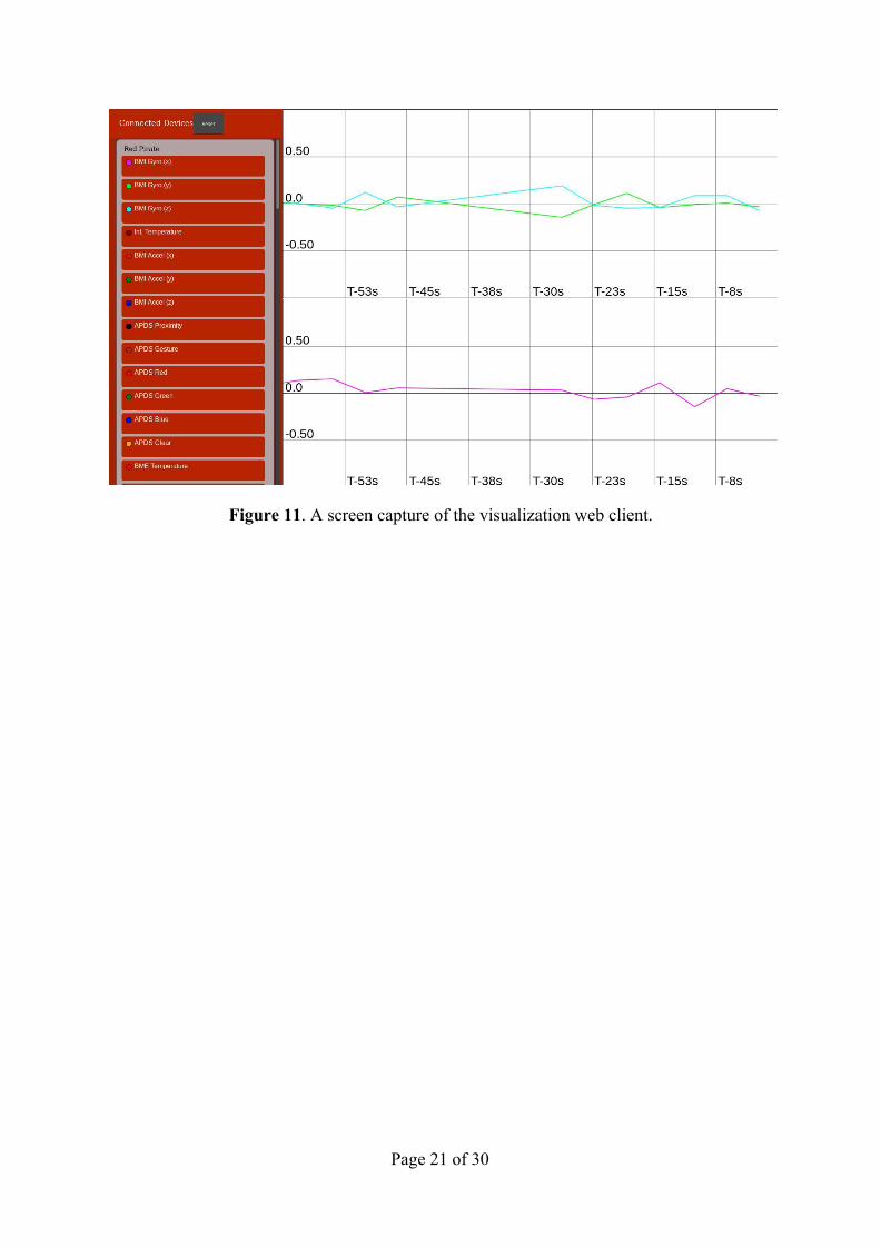
Figure 11. A screen capture of the visualization web client.
Page 21 of 30
6. Project Self-Assessment
6.1. Objectives As compared with the project plan, we completed approximately two thirds of the planned features for the device, and more features than planned for the server. The causes are two-fold: one member of the group vanished, and the firmware turned out to be more difficult to write than what we had expected. On the other hand, the code for the server proved to be much easier than what had been expected.
6.2. Schedule Due to the difficulties encountered in writing the firmware, we fell a week or two behind in schedule; thankfully, the hard work and excellent team spirit of Teemu and Thao allowed us to catch up with the schedule in no time, and the firmware was completed on-time.
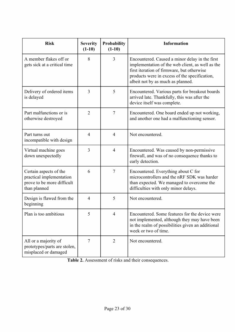
6.3. Risk Analysis Below is the table that we produced along with the project plan, with some minor changes (Table 2). Namely, we have replaced the notes on countermeasures with information on whether the unfortunate event was encountered or not, and how it was handled.
Page 22 of 30
Risk Severity (1-10)
Probability (1-10)
Information
A member flakes off or gets sick at a critical time
8 3 Encountered. Caused a minor delay in the first implementation of the web client, as well as the first iteration of firmware, but otherwise products were in excess of the specification, albeit not by as much as planned.
Delivery of ordered items is delayed
3 5 Encountered. Various parts for breakout boards arrived late. Thankfully, this was after the device itself was complete.
Part malfunctions or is otherwise destroyed
2 7 Encountered. One board ended up not working, and another one had a malfunctioning sensor.
Part turns out incompatible with design
4 4 Not encountered.
Virtual machine goes down unexpectedly
3 4 Encountered. Was caused by non-permissive firewall, and was of no consequence thanks to early detection.
Certain aspects of the practical implementation prove to be more difficult than planned
6 7 Encountered. Everything about C for microcontrollers and the nRF SDK was harder than expected. We managed to overcome the difficulties with only minor delays.
Design is flawed from the beginning
4 5 Not encountered.
Plan is too ambitious 5 4 Encountered. Some features for the device were not implemented, although they may have been in the realm of possibilities given an additional week or two of time.
All or a majority of prototypes/parts are stolen, misplaced or damaged
7 2 Not encountered.
Table 2. Assessment of risks and their consequences.
Page 23 of 30

7. Discussion and Conclusions
7.1. Alexey Ganzhinov My responsibilities on the project were deciding what parts we are going to be used, designing the Sensor Board, designing the case and making website. When starting this course I didn't have any idea about KiCAD, electronic design, 3D modeling and making websites. Also i had little experience in soldering. Now after designing and assembling professional looking device from the ground up I can say that I learned to use KiCAD and something about electronic design. And after making case and our website I learned some basic of 3D modeling and web programming.
In general it has been eye opening to see how much other work goes into making this project work and how other parts of the pipeline were made. Partly because of such great team work the project succeeded as well as it did, despite that we had some unexpected difficulties in each part of the project.
7.2. Thao Nguyen My main task in the project was to build the firmware focused on packing and broadcasting beacon data. I have achieved new techniques of firmware development, understanding of technical datasheets and software documentation, applying bluetooth protocol and cryptography. Since building the firmware took me most of the project duration, I could not manage to contribute a part of the hardware design or web development as planned at the beginning of the project. However, through team work, all my own learning targets are pretty much satisfied with acquirement of relevant knowledge of those sites and so skillful soldering techniques.
Page 24 of 30
7.3. Veli-Matti Rantanen Having spent the summer working on this project has taught me many things about project planning - especially that one should always assume that whatever can go wrong, will go wrong, and that diversions and delays should always be expected. Furthermore, I have learned that group decisions should be made fast and well ahead of time, to stop the project from stalling.
The project in general has taught me a lot about collaboration, and the importance of clear and informative documentation. It has also taught me how to write longer reports without actually adding any additional information to the report.
7.4. Teemu Vierros During the project I mainly focused on writing the firmware and was mostly responsible for communicating with all the different sensors and setting them up. Not having had any prior programming experience with microcontrollers before the project I feel like I gained a lot from this experience. Having to communicate with many different APIs during the development of the firmware gave me the ability to manage different kinds of protocols and tools.
Because of this project I got a great change to see and learn many of the skills needed in creating IoT devices.
Page 25 of 30
Appendices
Appendix A. Device Schematic
Page 26 of 30
Page 27 of 30
Appendix B. Server Diagram
Page 28 of 30
Page 29 of 30
References [1] Nordic Software Development Kit v15.0.0
http://infocenter.nordicsemi.com/index.jsp?topic=%2Fcom.nordic.infocenter.sdk5.v15.0.0%2Findex.html&cp=4_0_1
[2] GitHub repository
https://github.com/cherri03ly25/at-iot
[3] Hash-based message authentication code (HMAC)
https://en.wikipedia.org/wiki/HMAC
[4] AES-256-ECB
https://en.wikipedia.org/wiki/Block_cipher_mode_of_operation#Electronic_Codebook_(ECB)
[5] General bluetooth advertising process
https://devzone.nordicsemi.com/b/blog/posts/bluetooth-smart-and-the-nordics-softdevices-part-1
[6] BMD-340
https://www.rigado.com/products/modules/bmd-340/
[7] APDS-9960
https://www.broadcom.com/products/optical-sensors/integrated-ambient-light-and-proximity-sensors/apds-9960
[8] BME280
https://www.bosch-sensortec.com/bst/products/all_products/bme280
[9] BMI055
https://www.bosch-sensortec.com/bst/products/all_products/bmi055
Page 30 of 30