Energy Trike w i t h A C C U b a t t e r y d r i v e a n d...
15
1 D110693#2 http://nl.opitec.com/opitec-web/st/downloads Materialen zijn te bestellen bij: Met uw leerlingen aan de slag ? Bestel de docentenhandleiding en het instructiemateriaal Teken en ontwerp De Energy Trike met het 3 D tekenpakket Solid Edge Bekijk de 3 D animatie op Youtube Stap in de wereld van Augmented Reality Stuur voor meer info een mail naar: HYPERLINK "mailto:[email protected]" [email protected] Necessary materials Fretsaw with metalworking blade Drills dia. 3, 5, 6, 7, 10 Machine vice with soft jaws Soldering iron, solder Side cutters Wire strippers Combination pliers Mole grips Screwdriver Spanner 5,5 Rivet gun Centre punch Sharp pencil Ruler Set square Insulation tape 110.693 Energy Trike with ACCU battery drive and LED lighting Please Note The OPITEC range of projects is not intended as play toys for young children.They are teaching aids for young people learning the skills of Craft, Design and Technolo- gy.These projects should only be undertaken and tested with the guidance of a fully qualified adult. The finished projects are not suitable to give to children under 3 years old. Some parts can be swallowed. Dan- ger of suffocation!
Transcript of Energy Trike w i t h A C C U b a t t e r y d r i v e a n d...

1D110693#2
is uniekhttp://nl.opitec.com/opitec-web/st/downloads
Materialen zijn te bestellen bij:
Met uw leerlingen aan de slag ? Bestel de docentenhandleiding en het instructiemateriaal
Teken en ontwerp De Energy Trike met het 3 D tekenpakket Solid EdgeBekijk de 3 D animatie op Youtube
Stap in de wereld van Augmented RealityStuur voor meer info een mail naar:
HYPERLINK "mailto:[email protected]" [email protected]
Necessary materials Fretsaw with metalworking bladeDrills dia. 3, 5, 6, 7, 10Machine vice with soft jawsSoldering iron, solderSide cuttersWire strippersCombination pliersMole gripsScrewdriverSpanner 5,5Rivet gunCentre punchSharp pencilRulerSet squareInsulation tape
110.693
E n e r g y T r i k e w i t h A C C U b a t t e r y d r i v e a n d
L E D l i g h t i n g
Please NoteThe OPITEC range of projects is not intended as play
toys for young children.They are teaching aids for young people learning the skills of Craft, Design and Technolo-gy.These projects should only be undertaken and tested
with the guidance of a fully qualified adult.The finished projects are not suitable to give to children under 3 years old. Some parts can be swallowed. Dan-
ger of suffocation!
2 D110693#1
INSTRUCTIONS
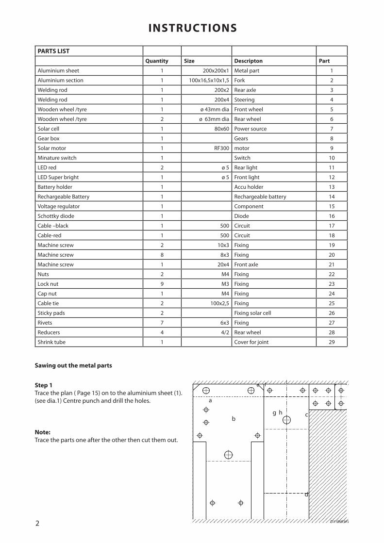
PARTS LISTQuantity Size Descripton Part
Aluminium sheet 1 200x200x1 Metal part 1
Aluminium section 1 100x16,5x10x1,5 Fork 2
Welding rod 1 200x2 Rear axle 3
Welding rod 1 200x4 Steering 4
Wooden wheel /tyre 1 ø 43mm dia Front wheel 5
Wooden wheel /tyre 2 ø 63mm dia Rear wheel 6
Solar cell 1 80x60 Power source 7
Gear box 1 Gears 8
Solar motor 1 RF300 motor 9
Minature switch 1 Switch 10
LED red 2 ø 5 Rear light 11
LED Super bright 1 ø 5 Front light 12
Battery holder 1 Accu holder 13
Rechargeable Battery 1 Rechargeable battery 14
Voltage regulator 1 Component 15
Schottky diode 1 Diode 16
Cable –black 1 500 Circuit 17
Cable-red 1 500 Circuit 18
Machine screw 2 10x3 Fixing 19
Machine screw 8 8x3 Fixing 20
Machine screw 1 20x4 Front axle 21
Nuts 2 M4 Fixing 22
Lock nut 9 M3 Fixing 23
Cap nut 1 M4 Fixing 24
Cable tie 2 100x2,5 Fixing 25
Sticky pads 2 Fixing solar cell 26
Rivets 7 6x3 Fixing 27
Reducers 4 4/2 Rear wheel 28
Shrink tube 1 Cover for joint 29
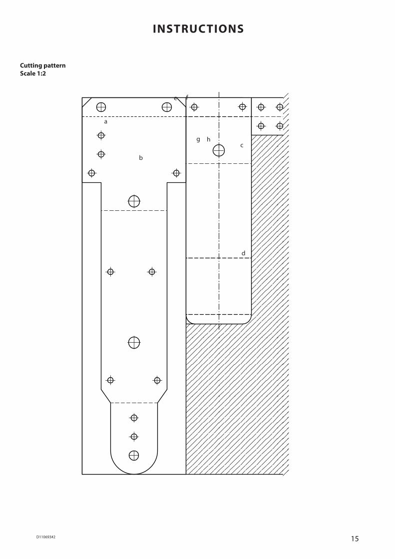
Sawing out the metal parts
Step 1 Trace the plan ( Page 15) on to the aluminium sheet (1). (see dia.1) Centre punch and drill the holes.
Note:Trace the parts one after the other then cut them out.
a
b
e f
g h c
d
3D110693#2
90°
135°90
°
45°
135°
135°135°
135°
50°
45°
140° 140°
90°
90°
90°
90°
135°90
°
45°
135°
135°135°
135°
50°
45°
140° 140°
90°
90°
90°
90°
135°90
°
45°
135°
135°135°
135°
50°
45°
140° 140°
90°
90°
90°
90°
135°90
°
45°
135°
135°135°
135°
50°
45°
140° 140°
90°
90°
90°
90°
135°90
°
45°
135°
135°135°
135°
50°
45°
140° 140°
90°
90°
90°
90°
135°90
°
45°
135°
135°135°
135°
50°
45°
140° 140°
90°
90°
90°
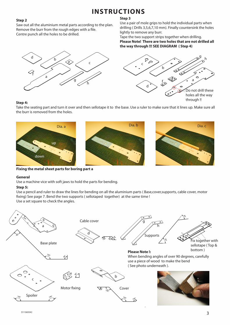
INSTRUCTIONSStep 2Saw out all the aluminium metal parts according to the plan. Remove the burr from the rough edges with a file.Centre punch all the holes to be drilled.
Step 3Use a pair of mole grips to hold the individual parts when drilling ( Drills 3,5,6,7,10 mm). Finally countersink the holes lightly to remove any burr.Tape the two support strips together when drilling.Please Note! There are two holes that are not drilled all the way through !!! SEE DIAGRAM ( Step 4)
Fixing the metal sheet parts for boring part a
General Use a machine vice with soft jaws to hold the parts for bending.
Base plate
Cover
Supports
Spoiler
Cable cover
Motor fixing
Step 5:Use a pencil and ruler to draw the lines for bending on all the aluminium parts ( Base,cover,supports, cable cover, motor fixing) See page 7. Bend the two supports ( sellotaped together) at the same time !Use a set square to check the angles.
Do not drill these holes all the way through !!
Step 4:Take the seating part and turn it over and then sellotape it to the base. Use a ruler to make sure that it lines up. Make sure all the burr is removed from the holes.
Dia. a Dia. b Dia. c
Please Note !: When bending angles of over 90 degrees, carefully use a piece of wood to make the bend( See photo underneath ).
a
bc
de
fg
h
down
up
Fix together with sellotape ( Top & bottom )
cb
d
gh
aef
a
d
gh
ce
b

4 D110693#1
252550
150° 150°
712
1727
70100
5
Ø 5 Ø 3
Ø 4R5 R0,5
Ø 5
4
Assembling the solar trike
INSTRUCTIONS
Step 7:Cut the welding rod (4) handlebars to 100mmBend to shape as shown. See the pattern on page 7.
Step 6:Mark 30mm with a pencil on the aluminium on the U section (2).Carefully saw the section as shown in the dra-wing so that the left sideis left. File any sawn edges smooth.
Constructing the front axle and steering
8. Mount the fork on the base frame using two machine screws (19) from the top. Insert the steering from the side and clamp it in position. Add the aluminium part (f ) under-neath and fix with two stop nuts (23)
9. Set the battery holder (13) dia.9 in the basic frame, so that the red cable faces the fork and the black faces the rear of the trike . Line up the holes and rivet the holder in place.
10. Fix the motor holder (e) to the back of the gearbox using a machine screw (20) and nut (23) Drill the second hole 3mm dia. and insert a screw (20) and nut (23).
Dia. 8
Dia. 9
Dia. 10
before drilling mark the centre!!
Mark out with a pencil the holes in the top. Use sellotape to hold the fork on the frame. Drill the first 3mm hole and then insert a machine screw (19) and nut (23).Then drill the remaining holes. Remove the sellotape and remove any burr from the holes.
Note 1:Before cabling the solar trike cut the cables to length according to the plan. Remove about 10mm insulation from the ends and twist wire strand together. All the ends with solder and then trim the ends to 8mm long.
Flat side of rivet on top To fix the battery holder
3mm holeDrill through
Note 2:Before connecting the voltage block, tin the connections. Then solder the black and red cables as shown.
Note 3:On the plan ( See page 7) the points are shown with ( 0 ) where the shrink cover must be added before making the cable connection.
a
f
5D110693#2
Dia.13
INSTRUCTIONS
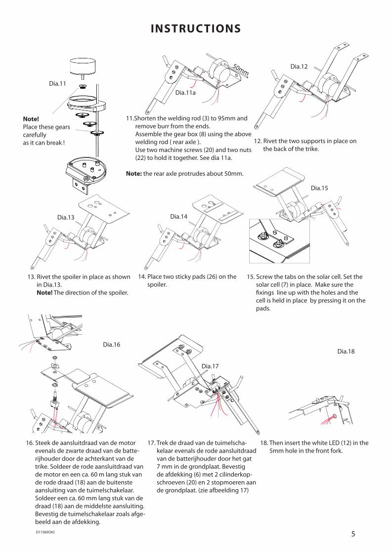
13. Rivet the spoiler in place as shown in Dia.13. Note! The direction of the spoiler.
14. Place two sticky pads (26) on the spoiler.
Dia.14
Dia.15
15. Screw the tabs on the solar cell. Set the solar cell (7) in place. Make sure the fixings line up with the holes and the cell is held in place by pressing it on the pads.
16. Steek de aansluitdraad van de motor evenals de zwarte draad van de batte-rijhouder door de achterkant van de trike. Soldeer de rode aansluitdraad van de motor en een ca. 60 m lang stuk van de rode draad (18) aan de buitenste aansluiting van de tuimelschakelaar. Soldeer een ca. 60 mm lang stuk van de draad (18) aan de middelste aansluiting. Bevestig de tuimelschakelaar zoals afge-beeld aan de afdekking.
Dia.16
17. Trek de draad van de tuimelscha-kelaar evenals de rode aansluitdraad van de batterijhouder door het gat 7 mm in de grondplaat. Bevestig de afdekking (6) met 2 cilinderkop-schroeven (20) en 2 stopmoeren aan de grondplaat. (zie afbeelding 17)
Dia.17
18. Then insert the white LED (12) in the 5mm hole in the front fork.
Dia.18
Dia.12
11.Shorten the welding rod (3) to 95mm and remove burr from the ends. Assemble the gear box (8) using the above welding rod ( rear axle ). Use two machine screws (20) and two nuts (22) to hold it together. See dia 11a.
Note: the rear axle protrudes about 50mm.
Dia.11a
12. Rivet the two supports in place on the back of the trike.
Note!Place these gearscarefully as it can break !
Dia.11
50mm
6 D110693#1
+ -
ANODE long leg = + plus
CATHODE short leg = - minus
Cabling – For the lengths see the plan on page 7 :
INSTRUCTIONS
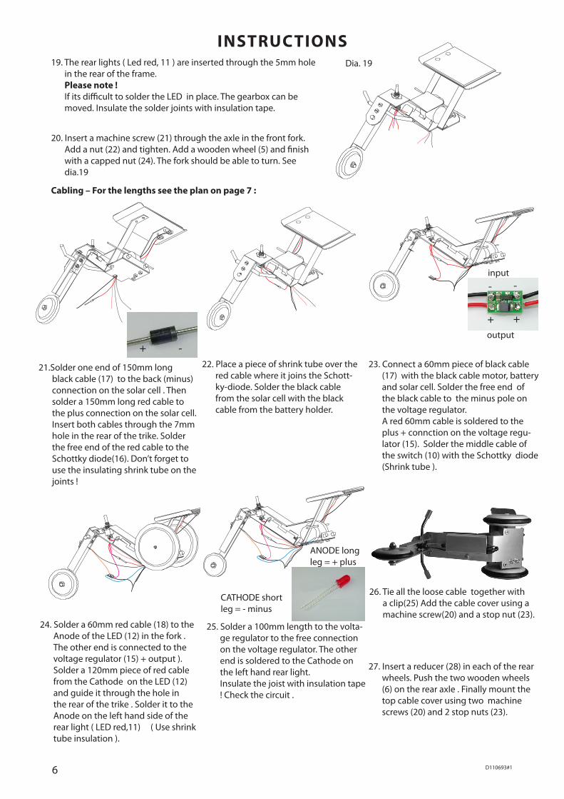
21.Solder one end of 150mm long black cable (17) to the back (minus) connection on the solar cell . Then solder a 150mm long red cable to the plus connection on the solar cell. Insert both cables through the 7mm hole in the rear of the trike. Solder the free end of the red cable to the Schottky diode(16). Don’t forget to use the insulating shrink tube on the joints !
22. Place a piece of shrink tube over the red cable where it joins the Schott-ky-diode. Solder the black cable from the solar cell with the black cable from the battery holder.
23. Connect a 60mm piece of black cable (17) with the black cable motor, battery and solar cell. Solder the free end of the black cable to the minus pole on the voltage regulator.
A red 60mm cable is soldered to the plus + connction on the voltage regu-lator (15). Solder the middle cable of the switch (10) with the Schottky diode (Shrink tube ).
24. Solder a 60mm red cable (18) to the Anode of the LED (12) in the fork . The other end is connected to the voltage regulator (15) + output ). Solder a 120mm piece of red cable from the Cathode on the LED (12) and guide it through the hole in the rear of the trike . Solder it to the Anode on the left hand side of the rear light ( LED red,11) ( Use shrink tube insulation ).
25. Solder a 100mm length to the volta-ge regulator to the free connection on the voltage regulator. The other end is soldered to the Cathode on the left hand rear light. Insulate the joist with insulation tape ! Check the circuit .
26. Tie all the loose cable together with a clip(25) Add the cable cover using a machine screw(20) and a stop nut (23).
19. The rear lights ( Led red, 11 ) are inserted through the 5mm hole in the rear of the frame. Please note ! If its difficult to solder the LED in place. The gearbox can be moved. Insulate the solder joints with insulation tape.
Dia. 19
20. Insert a machine screw (21) through the axle in the front fork. Add a nut (22) and tighten. Add a wooden wheel (5) and finish with a capped nut (24). The fork should be able to turn. See dia.19
27. Insert a reducer (28) in each of the rear wheels. Push the two wooden wheels (6) on the rear axle . Finally mount the top cable cover using two machine screws (20) and 2 stop nuts (23).
+ +
- -input
output
7D110693#2
M
Spannungs-�wandler
+
-
+
+
-
+
-
+
-
-
LED�weiß
LED�rot
LED�rotSchottky�
DiodeSchalter
AkkuSolar-�zelle
+
-
+ +
- -
100
60 60
140
150 70
110
60
120
60
60
70
90°
135°90
°
45°
135°
135°135°
135°
50°
45°
140° 140°
90°
90°
90°
90°
135°90
°
45°
135°
135°135°
135°
50°
45°
140° 140°
90°
90°
90°
90°
135°90
°
45°
135°
135°135°
135°
50°
45°
140° 140°
90°
90°
90°
90°
135°
90°
45°135°
135°
135°
135°
50°
45°
140°140°
90°
90° 90°
90°
135°90
°
45°
135°
135°135°
135°
50°
45°
140° 140°
90°
90°
90°
90°
135°90
°
45°
135°
135°135°
135°
50°
45°
140° 140°
90°
90°
90°
Anode = Long =+
Cathode= Short = -
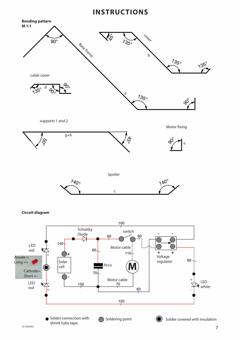
Circuit diagram
SchottkyDiode
Solder connection with shrink tube tape.
Voltage regulator
LED white
LED red
Solar cell Accu
INSTRUCTIONSBending pattern M 1:1
Base frame
cover
supports 1 and 2Motor fixing
Spoiler
cable cover
LED red
switch
Soldering point Solder covered with insulation
M+
+
-
-
+
-
b
ad
g+h
e
c
Motor cable
Motor cable

8 D110693#1

9D110693#2
5
10
45
55
5
20
5
45
6093
55
130
150
155
162
200
10
2030
30
5 8
Ø 5
Ø 3
Ø 7
Ø 3
Ø 3
Ø 5
25
R 12,5
Ø 7
10
Ø 3
5 5
35
INSTRUCTIONSPattern for the base frame(a)Scale 1:1

10 D110693#1

11D110693#2
28
Ø 6
120
35
4
25
35
105
35
Ø 3
17,5
712
1727
70100
5
Ø 5 Ø 3
Ø 4R5 R0,5
Ø 5
4
1020
10
R 2
1020
10 20
Ø 3 Ø 3
INSTRUCTIONS Pattern for cover (b)Scale 1: 1
Pattern for the forksScale 1: 1
Pattern for the clip and motor fixing ( f+e)Scale 1: 1

12 D110693#1
13D110693#2
252550
150° 150°
520
25
4
10
110
Ø 3
R 2
10
1220
3378
98110
20
40
60R 5
Ø 3
Ø 1025
5527,5
51018
4045
R5
Ø 3
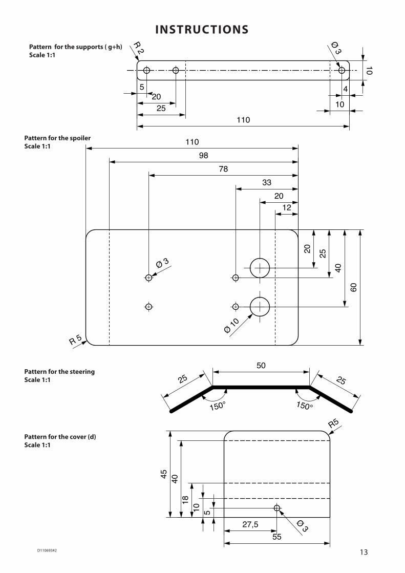
INSTRUCTIONS Pattern for the supports ( g+h) Scale 1:1
Pattern for the spoilerScale 1:1
Pattern for the steering Scale 1:1
Pattern for the cover (d) Scale 1:1

14 D110693#1
15D110693#2
Cutting patternScale 1:2
INSTRUCTIONS
a
b
e f
g hc
d