Handboek voor ISO 9001 14001 27001, PREZO, MVO, VCA, OHSAS, HACCP, HKZ
EN
ITD
EE
SF
RP
LR
U
General instructions for safe use
Allgemeine Anweisungen für einen Sicheren Gebrauch
Instructions générales pour une utilisation sûre
Istruzioni generali per un uso sicuro
Instrucciones generales para un uso seguro
Instrukcje ogólne dotyczące bezpiecznego użytkowania
Общие указания для безопасного использования
ISO 9001 – ISO 14001 – BS OHSAS 18001
ISO 9001 – ISO 14001 – BS OHSAS 18001
ISO 9001 – ISO 14001 – BS OHSAS 18001
ISO 9001 – ISO 14001 – BS OHSAS 18001
ISO 9001 – ISO 14001 – BS OHSAS 18001
ISO 9001 – ISO 14001 – BS OHSAS 18001
ISO 9001 – ISO 14001 – BS OHSAS 18001
THE ORIGINAL VERSION OF THESE INSTRUCTIONS IS IN ITALIAN
MT IG TK GEN 12 2019
EN GENERAL INSTRUCTIONS FOR SAFE USE
IT ISTRUZIONI GENERALI PER UN USO SICURO
DE ALLGEMEINE ANWEISUNGEN FÜR EINEN SICHEREN GEBRAUCH
ES INSTRUCCIONES GENERALES PARA UN USO SEGURO
FR INSTRUCTIONS GÉNÉRALES POUR UNE UTILISATION SÛRE
PL INSTRUKCJE OGÓLNE DOTYCZACE BEZPIECZNEGO UZYTKOWANIA
RU ОБЩИЕУКАЗАНИЯДЛЯБЕЗОПАСНОГОИСПОЛЬЗОВАНИЯ
LANGUAGES SUMMARY
04
29
54
79
104
129
154
03
Heat Exchange SolutionsThermoKey
02 MT IG TK GEN 12 2019

General instructions for safe use
Quality Management System ISO 9001
Environmental Management System ISO 14001
Occupational Health and Safety Management System
BS OHSAS 18001
MT IG TK EN 12 2019
THE ORIGINAL VERSION OF THESE INSTRUCTIONS IS IN ITALIAN
EN
MT IG TK EN 12 2019MT IG TK EN 12 2019
ThermoKey IG - General instructions for safe use Manuals IG
0605
EN
READ CAREFULLY AND BE SURE TO THOROUGHLY UNDERSTAND ALL THE INFORMATION PROVIDED IN THESE INSTRUCTIONS BEFORE PLANNING AND, IN ALL CASES, BEFORE CARRYING OUT ANY HANDLING, UNPACKING, ASSEMBLING, POSITIONING AND COMMISSIONING OPERATION INVOLVING THE UNIT.
The Manufacturer declines any and all liability for injuries to people or damage to property arising from failure to observe the indications in this document.
The original version of this manual is in Italian and can be found on our website: www.thermokey.comThe English translation conforms to the original and can be found on our website: www.thermokey.comTranslations may contain mistakes. In case of doubt, always refer to the original Italian version or to its English translation.
Heat Exchange SolutionsThermoKey
PHILOSOPHY OF THE MANUAL
Para. § 255 of the applicative guidelines, revision 2, in the 2006/42/EC Machinery Directive suggests that instructions should be provided in electronic form on the Internet in order to prevent their loss and foster their updating.Moreover, para. § 275 establishes that there should be correspondence between technical-commercial publications, such as catalogues, and the manual.Many of the units manufactured by ThermoKey are customized for a specific plant or customer.Due to the above-mentioned points, and considering that instruction readers are plant designers, installers and – finally - users, the technical documentation for correct unit designing and use follows the philosophy of drawing up a set of documents which, as a whole, are in fact defined as the MANUAL.
GENERAL INSTRUCTIONS FOR SAFE USE (IG)
INSTRUCTIONS FOR HANDLING AND UNPACKING (IM)
INSTRUCTIONS AND TECHNICAL SPECIFICATIONS (TC)
SPECIFIC USE AND MAINTENANCE INSTRUCTIONS (IS)
THE STRUCTURE OF THE MANUAL IS INDICATED HEREAFTER
MT IG TK EN 12 2019MT IG TK EN 12 2019
ThermoKey IG - General instructions for safe use Manuals IG
0807
EN
The “General Instructions for Safe Use” provide information on safety and correct use. They include the following sections:
IG 1. PRELIMINARY NOTICESIG 1.1 ACHIMEDE SOFTWARE'S NOTES
IG 2. LEGAL NOTICESIG 2.1 ORIGINAL VERSION
IG 2.2 LIMITATIONS TO THE USE OF THIS MANUAL
IG 2.3 CONTENT AND UNDERSTANDING OF THE MANUAL
IG 2.4 LIABILITY
IG 2.5 LAW AND TECHNICAL NORMS USED IN BUILDING THE UNIT
IG 2.6 IMPORTANCE OF THE EN 378 SET OF NORMS
IG 3. PLAQUE AND GENERAL LABELS
IG 4. GENERAL WARNING AND SAFETY REGULATIONSIG 4.1 GENERALITIES
IG 4.2 HANDLING, LOADING AND UNLOADING
IG 4.3 TRANSPORT
IG 4.4 WAREHOUSE STORAGE
IG 4.5 FAN NOTES
IG 4.6 ELECTRICAL SAFETY
IG 4.7 MECHANICAL SAFETY
IG 5. WRONG AND FORBIDDEN USEIG 5.1 SPECIFIC PROHIBITIONS FOR AMMONIA UNITS
IG 6. GENERAL RESIDUAL RISKSIG 6.1. PPE PERSONAL PROTECTIVE EQUIPMENT AND DANGERS
IG 6.2 AMMONIA LEAKS/SPILLS
IG 6.3 INSTRUCTIONS FOR INJURY TREATMENT
IG 7. INSTALLATION – GENERAL AND COMMON NOTICESIG 7.1 MINIMUM TECHNICAL SPACES
IG 7.2 INSPECTION UPON DELIVERY
IG 7.3 UNPACKING THE UNIT
IG 7.4 PLACEMENT
IG 8. INSTALLATIONS
IG 9. REFRIGERATION AND HYDRAULIC CONNECTIONSIG 9.1 HYDRAULIC CONNECTIONS
IG 9.2 ASSEMBLING PIPING
IG 9.3 WELDING
IG 10. ELECTRICAL CONNECTION
INDEX
0910
1212
12
12
13
14
14
15
1515
15
15
16
16
16
17
1818
1919
22
22
2424
24
24
24
25
2525
26
26
26
§ In the “Instructions for Handling and Unpacking” the required and permitted handling and unpacking operations of the various air-cooled units are indicated by means of numbered figures. In case of special air-cooled units, the correct information will be identified in the documentation by the order confirmation number.
To facilitate updating and avoid ambiguity of information, this part of the documentation on the unit consists of catalogues and other technical documentation supplied directly by ThermoKey and/or to be found on the Internet website: www.thermokey.com.
§ The IT chapter “Instructions and Technical Specifications” illustrates the technical data related to every single kind of unit, grouped into families. It includes:
- SIZES AND WEIGHTS
- SPACE TAKEN UP AND MINIMUM TECHNICAL SPACE
- AERAULIC PERFORMANCE AND ELECTRICAL DATA
- SOUND EMISSION LEVEL
- ELECTRICAL SCHEMES
- TECHNICAL BULLETIN
“Specific Use and Maintenance Instructions” are normally specific to every model and, where necessary, to each individual fan unit. They include:
IS 1 - OPERATING INSTRUCTIONS
IS 2 - OPERATING PROBLEMS
IS 3 - MAINTENANCE
IS 4 - SPARE PARTS
IG 11. REFRIGERANTIG 11.1 AMMONIA AS REFRIGERANT FLUID
IG 11.2 "H" HAZARD AND "P" PRECAUTIONS
IG 12. INSPECTABLE FAN UNITS
2727
28
28
MT IG TK EN 12 2019MT IG TK EN 12 2019
ThermoKey IG - General instructions for safe use Manuals IG
1009
EN
IG 1. Preliminary notesTHE UNIT SHALL BE USED EXCLUSIVELY ACCORDING TO ITS INTENDED USE, AS SPECIFIED IN PARAGRAPH “PRELIMINARY NOTES “.
1. As the preliminary notes are an essential part of the manual, they must be read with great care and fully understood.
2. This manual – a part of the technical documentation of the fan unit - may be integrated with further indications and partly modified for the benefit of customization, or non-standard operational conditions. Generally, the manual consists of a main part and of some technical annexes. For the sake of simplicity, hereafter, where not otherwise specified, reference shall be made to the manual meaning all the technical documentation necessary for the correct use of the fan unit.
3. Keep this manual throughout the entire life-cycle of the fan unit.
4. Pay great attention to the norms of use provided in this manual, since failure to observe them may damage the fan unit or property, and/or harm people or animals.
5. ThermoKey reserves the right to modify this manual at any time. The final text of the revisions shall always be made public through publication on the website: www.thermokey.com. To ascertain if you are equipped with the latest revision, consult the revision index.
6. The Manufacturer’s data and reference to the customer’s order number are indicated on the ID plate of the fan unit, including the order number and data specific to the unit.
7. Non-original spare parts have to be previously approved by ThermoKey.
8. The unit conforms to the Essential Health and Safety Requirements laid down in the Machinery Directive 2006/42/EC, which apply to all the contemplated standard use conditions, or to those agreed with the customer.
9. Any other use from that contemplated and described in this manual and/or that has not been agreed between the User and ThermoKey before the manufacturing/commissioning of the fan unit are explicitly forbidden. Improper use of the fan unit may cause dangerous conditions, for which ThermoKey takes no liability.
10. The fan unit is designed for exclusive use with the refrigerants indicated in the order identified with the number on the unit ID plate.
11. Use of refrigerant fluids different from those explicitly indicated is prohibited.
12. To use ammonia and group 1 refrigerants, additional prescriptions and indications to those provided in this section may be necessary, which are provided in the manual of the fan unit.
13. The use of substances and fluids that may deteriorate, make unsafe or diminish the performance of the fan unit is forbidden.
Reference to the order number is very important because it identifies possible customized solutions and limitations of use agreed upon between ThermoKey, as manufacturer, and the buyers in their capacity as users.
14. All technical data related to the fan unit, all use restrictions and the minimum features of the installation site are given in the technical catalogues.
15. ThermoKey must be immediately contacted in the following cases: modifications are necessary, or it is necessary to carry out a variation to the fan unit after it has been manufactured, but before its start up; the operational conditions of the installation site are not the ones contemplated; a difference exists between what was foreseen before manufacturing and the actual state of the installation site; and in any case before carrying out any modification work. Failure to do so shall relieve ThermoKey from any and all responsibility.
16. Project designers, installers and/or users are required to enforce local norms and regulations concerning installation, use and disposal of the fan unit.
17. Wherever not better specified in this manual, the term qualified personnel shall always indicate any duly informed person, or any person under the supervision of a worker having such training, knowledge and experience as to be able to carry out the work properly and allow the supervised person to perceive the risks and avert any related hazard.
18. For warranty conditions refer to the terms agreed at the order stage.
19. This manual may not be reproduced, either totally or partially, unless the manufacturer gives its authorization in writing. Updated copies of this manual can be found on the website www.thermokey.com
IG 1.1. ACHIMEDE SOFTWARE'S NOTES1. The voltage is referred to the supplier's nominal data: fans consumption may vary with the air temperature and voltage system.
2. The unit may not be suitable for very corrosive atmosphere. For special applications contact ThermoKey. If a special fin material is selected(copper,coating),all the other materials of the unit remain standard(for detailed information please check the Technical description of the unit).
3. Dimensions and weight are not valid for all possible options! The overall dimensions on the data sheet relate to the units without controls /electrical panels (For more detailed information please refer to the Electrical Box Manual). In the case of horizontal air flow units the standard position of the connections is on the left looking at the finned pack.
4. Any noise caused by control systems, adiabatic system and so on, is not considered in the fan noise declaration. Actual values can also be subject to changes depending on the conditions of the installation.
5. The manual consists of 4 parts; IG = General instructions for safe use, IM = Instructions for handling and unpacking, TC = Instructions and technical specifications , IS = Specific use and maintenance instructions. If not expressly requested at the pre-Purchase Order stage, the TC and IS instructions must be downloaded by the user from www.thermokey.com as they will not be provided in paper format.
The installer is required to follow the instructions of the above manuals and of all the main electrical components’ manuals (e.g. fans, pumps, regulators).
6. The unit is equipped with fans that follow the efficiency requirements of ERP directive 2009/125/EC
7. In accordance with EN 13487 the declared sound pressure level for this unit has been calculated in free-field conditions over a reflecting plane with a parallelepiped surface. With reference to ISO 3744, when the difference of measurement
MT IG TK EN 12 2019MT IG TK EN 12 2019
ThermoKey IG - General instructions for safe use Manuals IG
1211
EN
IG 2. Legal notesIG 2.1. ORIGINAL VERSIONThe original version of this manual is in Italian and comes with every official translation of the manual. Translations, which are unauthorized by the manufacturer, are not to be deemed valid.
The use of unauthorized copies and/or translations of this manual and/or the use of translations lacking the original Italian version relieve ThermoKey from any possible consequence and liability in case of an accident.
IG 2.2. LIMITATIONS TO THE USE OF THIS MANUALThis user and maintenance manual was drawn up for the fan units destined to the European Community market, bearing the CE trademark.
This user and maintenance manual does not cover placing on the market and/or use of the units in countries outside the European Union.
IG 2.3.CONTENT AND UNDERSTANDING OF THE MANUALShould project designers, installers and/or users (generally and comprehensively identified as operators) fail to find the required technical information on installation, use, maintenance and/or safe disposal of the unit in this manual, or should they have doubts on correct installation, use, maintenance and/or disposal procedures, they must get in touch with ThermoKey. This user and maintenance manual was drawn up to be as complete and clear as possible for its readers, depending on their preparation and competencies.Failure to understand the content of this manual, or incomplete understanding of the instructions contained in it, is a sufficient condition for immediately interrupting designing, installation, use, maintenance and/or disposal of the unit itself.
Should operators persist in their activity without having perfectly and completely understood this user and maintenance manual and/or without mastering all the know-how and indications required to carry out their activity, ThermoKey shall be relieved from any consequence and liability.
The term negligence to ThermoKey includes failure to notify whatever mistake, omission, misprint, incongruous factor, etc. in this manual relating to technical instructions and indications: project designers, installers and users (maintenance operators) have to promptly notify ThermoKey regarding situations that may reduce safety for people,
of the unit in on and off stage is < = 6 dB ( A) , the the sound measurement does not reach the accuracy as required by the Directive. Background noise values lower than 30dB ( A) are typical of indoor and silent environments. The declaration of the sound pressure of the unit, stated on the ThermoKey data sheets, considers the background noise negligible.
8. S x x x x : id serial number of the combination of the standand options available on Archimede (listed and described in the ACCESSORIES section) and special on request. The code appears on the order confirmation (as a part of the model code description ) and on the data plate of the unit . Note : For each range the available options are listed in the catalogue on the Table Options and Accessories . The register of combinations of options associated with the code S x x x x is available on request .
9. Delivery time for standard unit is considered ex works. For any special terms and conditions (ex. Large quantities,special items..) please contact Sales dept.
10. The standard unit is not self-draining: the choice of fluid (water / glycol) is closely related to the freezing point of the same and to the actual operating period of the unit. For a self-draining construction, please contact ThermoKey for a special offer.
11. The air throw declared in the data sheets is the distance from the fan when the air speed corresponds to 0.25m/s.The air throw ir referred only to the default air flow of the fan : for cubic , light cubic and commercial models with delta or single-phase operation, for dual flow models with connection defined by the series
12. The dimensioning is made through a simulation of the selection program which does not take into account the influence of the installation conditions.
13. For the selection of the maximum operating pressure, the pressure related to the condensation temperature (i.e. middle point) is taken into account.
14. For fan units with microchannel cores, it is mandatory to respect the procedures available on ThermoKey website (Indications for the use of Tk micro cores)
15. Fluid Group related to Directive 2014/68 / CE.
16. The data on the fan label do not represent the worst absorption conditions.
17. The declared performances are suitable for HVAC applications with air flow in a free field on both coil and fan sides (e.g. avoid recirculation or any element that reduces airflow) and with uniform inlet temperatures to the coil (e.g. avoid conditions on which adjacent elements cause temperature variations at the unit inlet). For other critical applications (e.g. industrial, power) please contact ThermoKey.
18. ThermoKey reserves the right to change the technical data, drawings and prices of the Archimede software at any time and without prior notice. Please refer to the software release and EULA of the software in Section "?".
19. The Archimede software is based on Refprop's latest libraries of oils, refrigerants and blends. Data updates may result in different performances of the units than those of previous releases of Archimede.
20. Pay attention that the overall dimensions and weight of the unit equipped with EPS system, indicated in the technical sheet, refer to the model without electrical part and mounted evaporative panels, for variation of the possible option combinations please refer back to the following indications!Take into consideration that the evaporative modules mounted on the side of the model protrude of 440mm all together on the width of the model footprint, whereas they do not affect the length and height dimensions of the model, moreover
the discharging tubes mounted on the models protrude of extra 320mm all together on the width of the model. Take into consideration that the control panels and connection piping protrude depending on the selected and requested combinations of 400mm from the extremities of the model.Consider as 60 kilos each module (per fan) the operative weight of the evaporative modules mounted with wet panels. Pay attention that in the case of non optimal maintenance of the discharging drip-trays or of the discharging line, you should consider a possible store of water in the tray and of the sole discharging pipes of EPS system of about 30 kilos per module (per fan). Consider the pre-mounted connection piping of EPS system to water supply network on the model of about 25 kilos per unit. Consider weight of the possible pre-mounted control electrical panel of the EPS system on the model of about 35 kilos per unit.
MT IG TK EN 12 2019MT IG TK EN 12 2019
ThermoKey IG - General instructions for safe use Manuals IG
1413
EN
Incorrect identification of the operating conditions of the unit by the designers releases ThermoKey from any consequences and liability.
If the project is broken down into several sections, the project manager -whoever this is- shall be deemed to be the project designer.The installer is the person in charge of installation and implementation of the plant in conformity with project specifications, component specifications, as defined by their manufacturers, and good manufacturing practices. Installers must be expert and competent enough to clearly understand this user and maintenance manual, as well as any other technical-commercial document relating to the unit, and to ask the manufacturer for any possible clarification in order to implement a plant/system which is functional, safe and complies with good manufacturing practices.
The staff involved in the various operations for unit installation and commissioning must be competent and trained. Insofar as is relevant, the minimum level to be guaranteed is the one indicated in EN 13313.
If installation is broken down into several steps, the installation coordinator -whoever this is -shall be deemed to be the installer.
Responsibilities of the refrigeration plant/system operatorThe operator is the person who uses the plant and, therefore, the unit being the subject-matter of this user and maintenance manual. The operator is also responsible for unit maintenance.
The staff involved in the various operations for unit installation and commissioning have to be competent and trained. Insofar as is relevant, the minimum level to be guaranteed is the one indicated in EN 13313.
The plant/system operator must only work with competent and trained staff, equipped with the required individual protective equipment, and qualified for control, maintenance, repairs, emergency and disposal of the unit.As ThermoKey is not involved in design of the refrigeration plant/system and is released from any and all consequences and/or liability originating from incorrect design/installation.
As the units may undergo technical modifications and/or updates by the manufacturer, the plant/system operator must verify compatibility between the plant/system and the new version of the unit.
IG 2.5 STATUTORY REGULATIONS AND STANDARDS APPLIED FOR MANUFACTURING THE UNITFor the standards used by the manufacturer for building the unit always refer to ThermoKey Declaration sent with the unit.
IG 2.6.RELEVANCE OF EN 378 STANDARDSEN 378 represents a set of four technical standards (EN 378-1, EN 378-2, EN 378-3 and EN 378-4) which serve as major guidelines for the design, installation, operation, servicing and disposal of the plants and their related refrigeration units.The standards included in this set are aimed at providing a comprehensive overview of the safety aspects that have to be taken into account by designers, installers, plant/system operators and servicing staff.ThermoKey considers the enforcement of the standards of the EN 378 group of foremost importance for the safety of people, property and environment, in relation to the use of the air-cooled unit, subject of this manual, in a plant refrigeration system.Failure to comply with the prescriptions of these standards may primarily cause, and not within certain limits
property and the environment, and they must act with the required competence, professionalism, spirit of collaboration and diligence.
Any instance of negligent, reckless conduct or any action showing poor technical-professional competence shall release the manufacturer from any and all consequences and liability.
IG 2.4. LIABILITYManufacturer liabilityThe manufacturer is responsible for designing, building, testing and packing the fan unit in order to place it on the European Union market. The manufacturer guarantees that the fan unit is designed, built, tested and packaged in conformity with the essential requirements set out in the applicable Community directives, and that an appropriate conformity assessment has been carried out accordingly.Although the manufacturer is not in charge of packaging removal, installation, commissioning, maintenance, disassembly and disposal, these instructions contain as much useful information as possible on these operations throughout the life cycle of the fan unit.All unit parts have been designed, manufactured and tested so as to bear all reasonably foreseeable stress under expected use conditions and under reasonably foreseeable conditions: no safety and/or operating guarantee can be given if the units are used in conditions that are not explicitly contemplated by ThermoKey, and are therefore forbidden.
Installation, use, maintenance and/or disposal of the unit in forbidden conditions, not foreseen and/or anyway different from those contemplated by ThermoKey, relieve the latter from any and all consequences and liability.
Designer and installer liabilityInstallers and/or designers must evaluate the risks, prepare emergency, warning, notification and protection equipment and systems and have to also draft comprehensive instructions for the refrigeration plant/system on which the fan unit is installed, as prescribed by standard EN 378-4.
The designers and/or installers are also responsible for establishing best means and procedures for handling and storing the unit outside the manufacturer premises and/or warehouses. More specifically, the designers and/or installers must verify the instructions supplied by the manufacturer and have them complied with during handling, transport and storage.
Incorrect assessment of risks, or inadequate selection of emergency, warning, notification and protection means and systems by designers and/or installers shall release ThermoKey from any and all consequences and liability.
Designers are person in change of designing the refrigeration plant/system where the fan unit is installed: they are responsible for both performance and safety aspects. Designers have the responsibility of choosing the most appropriate components for the plant they are designing according to on the restrictions of use imposed by the manufacturer. Designers must be experienced and competent enough to clearly understand the content of this user and maintenance manual, as well as of other technical-commercial document relating to the unit and to ask the manufacturer for possible clarification in order to implement a functional, safe and state-of-the-art plant/system. In particular, designers have to be able to detect the reasonably foreseeable operating conditions of the unit (conditions relating to the environment, fastening means, loads and stresses, connections to the electrical, fluid, plumbing/hydraulic systems, etc.) and to verify that the unit is suitable for such conditions.

MT IG TK EN 12 2019MT IG TK EN 12 2019
ThermoKey IG - General instructions for safe use Manuals IG
1615
EN
Failure to comply with any of the requirements above and, generally, any conduct posing a risk for the operators involved in unit handling, releases the manufacturer from any and all consequences and liability.
Failure to comply with the above-mentioned indications may cause harm to people such as:- crushing- severing of limbs
Moreover it may damage the unit preventing it from working appropriately.
IG 4.3. TRANSPORTIn case of sea freight or land transport in particular (bumpy) road conditions, it is necessary to remove all the parts that might get damaged from the units, as this may cause future breakdown and malfunctioning, or to pack the units in special material.
Unit disassembly and reassembly must be carried out only after receiving ThermoKey's authorisation and solely following its direct and precise instructions. Failure to comply with this requirement relieves ThermoKey from all future liability.
IG 4.4. WAREHOUSE STORAGEIf the unit has to be stored before it is installed (for one or more than one month), it is advisable to adopt the following precautions:§ leave the fan unit in its original packaging until installation or re-package it so as to assure an equivalent level of
protection as the original packaging against atmospheric agents, dust, insects or small rodents,§ place in a covered area, with temperatures ranging between +15°C and +25ºC and a percentage of humidity between
50% and 70%;§ ensure the unit is not exposed to corrosive liquids or vapours.§ the units cannot be stacked one on top of the other during storage and transport, unless this is explicitly contemplated.
Failure to comply with storage indications shall relieve ThermoKey from all liability for damage caused by inappropriate storage of the unit.
IG 4.5. NOTES ON FANSIf the unit is installed outdoors, but it is not started up immediately, it is advisable to switch on its fan(s) for 4-6 hours at least once a week to avoid damage to the electric motors.
IG 4.6. ELECTRICAL SAFETY1. The electrical and hydraulic systems and the regulation units (optional) must be connected exclusively by qualified staff having the qualifications required by the legislation of the Country where the unit is going to be installed.
2. The fan unit is designed to operate within the voltage, frequency and current limits, and at the short-circuit conditions indicated on the ID plate.
§ either the risk of the refrigerant leaks or spillage, consequently leading to a fire or explosion, and/or harm to the health of people, damage to property and the environment;§ or the risk of accident for the people involved in the various stages such as installation, use, maintenance and disposal.
IG 3. Generic plates and labelsThe user must ensure that the labels and plates applied on the unit by the manufacturer are in good order, readable and properly secured in place. If they get worn out, unreadable or, in any case, hardly understandable, labels and plates have to be replaced.
IG 4. General warnings and safety rulesIG 4.1. GENERAL1. The air-cooled unit is contemplated for automatic, unsupervised use.
2. The designer and/or the installer will need to foresee fluid hammering.
3. The user shall be in charge of the fastening systems used in the fan unit and shall ensure that they have been designed in conformity with the ETAG requirements specifically relevant for this kind of support.
4. The users of fan units where hazardous fluids are used have to strictly adhere to the technical indications on fluid safety.
5. It is essential to provide for proper aeration of the area where fan units using potentially explosive or flammable fluids are fitted. Designers, installers and/or users must take this aspect into consideration.
6. Fans are designed for continuous operation S1 (continuous operation with constant load). If the fans are used with an ON/OFF regulation system, this control must not contemplate frequent switching (please read the fan data sheet).
7. In addition to the precautions contained in these chapters, specific instructions can be provided for each model (see ThermoKey website http://www.thermokey.com/Manuali.aspx).
IG 4.2. HANDLING, LOADING AND UNLOADING1. The plant/system must be handled and moved during loading and unloading by qualified staff supplied with suitable equipment, perfectly in line with the indications provided by the manufacturer.
2. In particular, the operators in charge of handling the unit have to:- verify that the lifting equipment they are using can bear the unit weight with a significant safety margin,- ensure that no-one is standing within the outreach of the equipment used for unloading and, in any case, within the area where such activity is being carried out,- ensure that the unit is hooked up with appropriate hooks only by the points indicated by the manufacturer.
MT IG TK EN 12 2019MT IG TK EN 12 2019
ThermoKey IG - General instructions for safe use Manuals IG
1817
EN
IG 5. Unintended and prohibited useAny different use from that specified in this manual is to be considered as unintended.While the fan unit is in operation, no activities are allowed near it, unless they take place at a suitable distance.Below is a list of foreseeable unintended uses:§ failure to disconnect the power supply by turning the power switch to position “O” (open) (or to disconnect the plug
from the socket) before performing adjustment, resetting and maintenance operations; § failure to carry out periodical maintenance and controls; § structural modifications or changes to the unit operating logics;§ tampering with the protections and safety systems;§ presence of unauthorised people during routine operation;§ failure by operators and maintenance people to wear personal protective equipment;§ failure to install the recommended collective protective equipment.
The behaviours illustrated above are explicitly prohibited.Since it is not possible to eliminate residual risks due to unintended use, indications and instructions are provided to avoid such conduct.It is prohibited to remove or make unreadable the safety, danger and obligation signs featured on the unit.It is prohibited to remove or tamper with the protections featured on the unit.It is prohibited to make modifications to the fan unit.
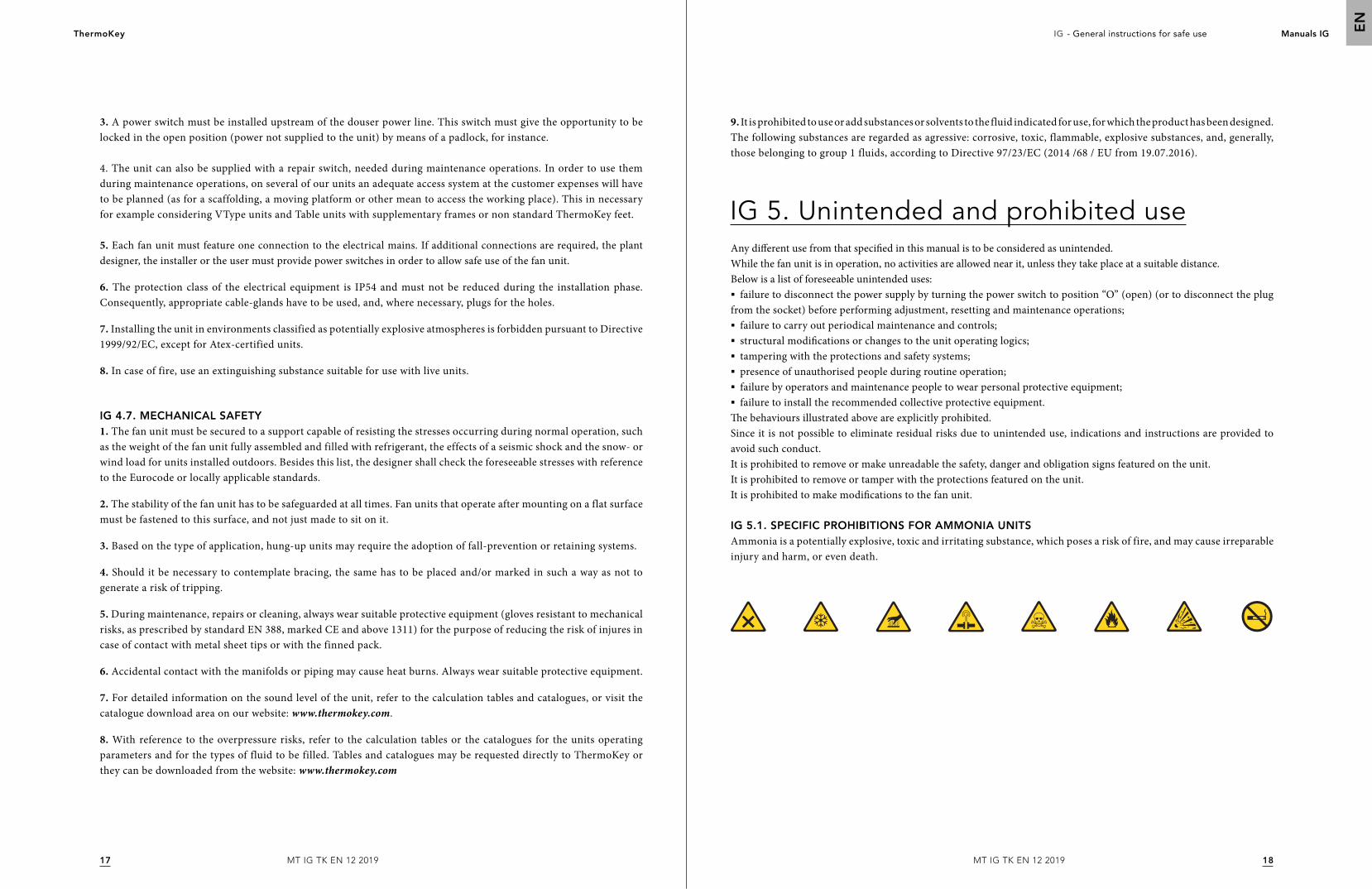
IG 5.1. SPECIFIC PROHIBITIONS FOR AMMONIA UNITSAmmonia is a potentially explosive, toxic and irritating substance, which poses a risk of fire, and may cause irreparable injury and harm, or even death.
9. It is prohibited to use or add substances or solvents to the fluid indicated for use, for which the product has been designed. The following substances are regarded as agressive: corrosive, toxic, flammable, explosive substances, and, generally, those belonging to group 1 fluids, according to Directive 97/23/EC (2014 /68 / EU from 19.07.2016).
3. A power switch must be installed upstream of the douser power line. This switch must give the opportunity to be locked in the open position (power not supplied to the unit) by means of a padlock, for instance.
4. The unit can also be supplied with a repair switch, needed during maintenance operations. In order to use them during maintenance operations, on several of our units an adequate access system at the customer expenses will have to be planned (as for a scaffolding, a moving platform or other mean to access the working place). This in necessary for example considering VType units and Table units with supplementary frames or non standard ThermoKey feet.
5. Each fan unit must feature one connection to the electrical mains. If additional connections are required, the plant designer, the installer or the user must provide power switches in order to allow safe use of the fan unit.
6. The protection class of the electrical equipment is IP54 and must not be reduced during the installation phase. Consequently, appropriate cable-glands have to be used, and, where necessary, plugs for the holes.
7. Installing the unit in environments classified as potentially explosive atmospheres is forbidden pursuant to Directive 1999/92/EC, except for Atex-certified units.
8. In case of fire, use an extinguishing substance suitable for use with live units.
IG 4.7. MECHANICAL SAFETY1. The fan unit must be secured to a support capable of resisting the stresses occurring during normal operation, such as the weight of the fan unit fully assembled and filled with refrigerant, the effects of a seismic shock and the snow- or wind load for units installed outdoors. Besides this list, the designer shall check the foreseeable stresses with reference to the Eurocode or locally applicable standards.
2. The stability of the fan unit has to be safeguarded at all times. Fan units that operate after mounting on a flat surface must be fastened to this surface, and not just made to sit on it.
3. Based on the type of application, hung-up units may require the adoption of fall-prevention or retaining systems.
4. Should it be necessary to contemplate bracing, the same has to be placed and/or marked in such a way as not to generate a risk of tripping.
5. During maintenance, repairs or cleaning, always wear suitable protective equipment (gloves resistant to mechanical risks, as prescribed by standard EN 388, marked CE and above 1311) for the purpose of reducing the risk of injures in case of contact with metal sheet tips or with the finned pack.
6. Accidental contact with the manifolds or piping may cause heat burns. Always wear suitable protective equipment.
7. For detailed information on the sound level of the unit, refer to the calculation tables and catalogues, or visit the catalogue download area on our website: www.thermokey.com.
8. With reference to the overpressure risks, refer to the calculation tables or the catalogues for the units operating parameters and for the types of fluid to be filled. Tables and catalogues may be requested directly to ThermoKey or they can be downloaded from the website: www.thermokey.com
MT IG TK EN 12 2019MT IG TK EN 12 2019
ThermoKey IG - General instructions for safe use Manuals IG
2019
EN
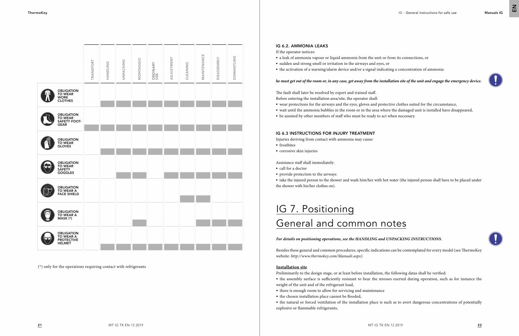
IG 6. General residual risksIG 6.1. PPE PERSONAL PROTECTIVE EQUIPMENT AND DANGERSThere are two categories of residual risks: general and specific risks. General residual risks are those which can be attributed to every fan unit, whatever the model or the application, and they are defined only based upon manufacturing technologies and solutions. General residual risks are examined in this part of the manual.On the other hand, specific residual risks are peculiar to a family of units, to a model, or even to a single sample unit. Specific residual risks are listed in the documentation specifically related to the unit, not necessarily in the manual.
1. The unit has risks that have not been totally eradicated from a design point of view or with the installation of adequate protections.
2. Besides the instructions given in this manual and in the technical documentation of the fan unit in general, the user has to implement organizational measures to further reduce residual risks. These measures include giving unit operators both personal (PPE) and collective (CPE) protective equipment.
3. During unit installation, sufficient space is contemplated to limit such risks. To preserve said conditions, the corridors and the areas around the unit must always be:
- free of obstacles (such as small ladders, tools, containers, boxes);- clean and dry;- well lit, if that is necessary.
4. Before disassembling the air cooled unit, which needs the lifting of the unit itself, it is mandatory to check the eventual corrosion of screws and lifting eyes. In the case of corrosion (even if little), before lifting the unit, substitute the screws and lifting eyes.
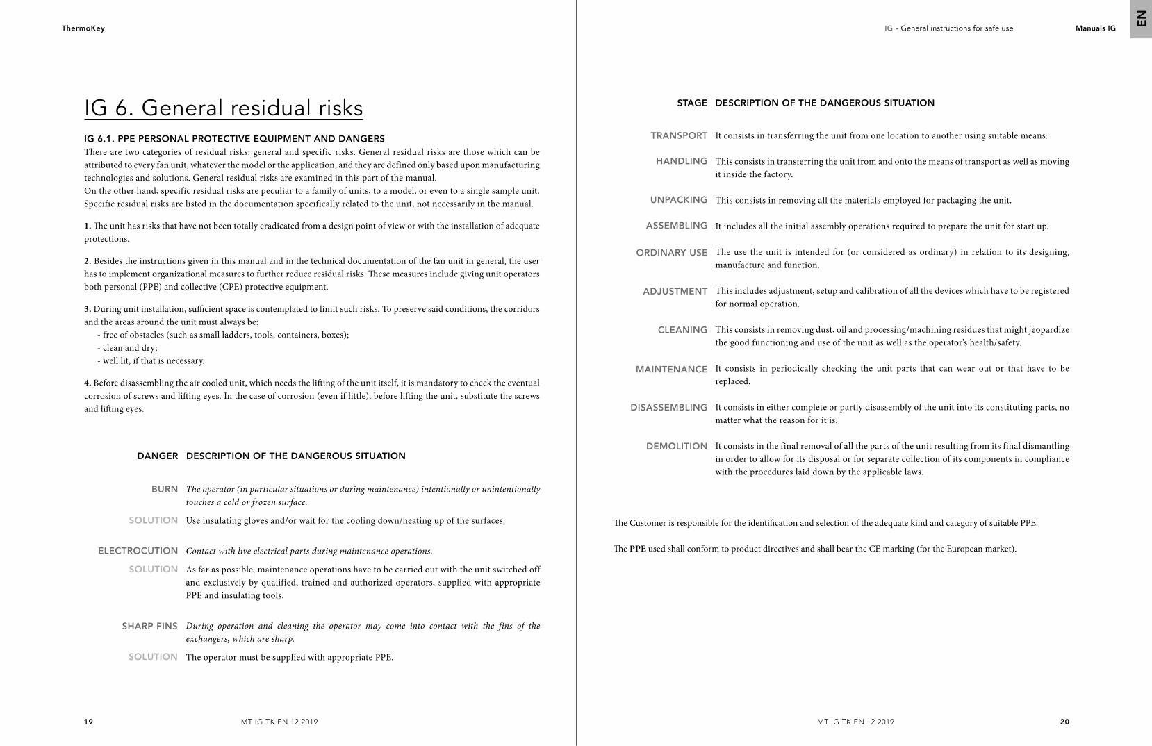
SOLUTION
SOLUTION
BURN
ELECTROCUTION
The operator (in particular situations or during maintenance) intentionally or unintentionally touches a cold or frozen surface.
Use insulating gloves and/or wait for the cooling down/heating up of the surfaces.
Contact with live electrical parts during maintenance operations.
As far as possible, maintenance operations have to be carried out with the unit switched off and exclusively by qualified, trained and authorized operators, supplied with appropriate PPE and insulating tools.
During operation and cleaning the operator may come into contact with the fins of the exchangers, which are sharp.
The operator must be supplied with appropriate PPE.SOLUTION
SHARP FINS
DESCRIPTION OF THE DANGEROUS SITUATIONDANGER
The Customer is responsible for the identification and selection of the adequate kind and category of suitable PPE.
The PPE used shall conform to product directives and shall bear the CE marking (for the European market).
STAGE DESCRIPTION OF THE DANGEROUS SITUATION
TRANSPORT
HANDLING
UNPACKING
ASSEMBLING
ORDINARY USE
ADJUSTMENT
CLEANING
MAINTENANCE
DISASSEMBLING
DEMOLITION
It consists in transferring the unit from one location to another using suitable means.
This consists in transferring the unit from and onto the means of transport as well as moving it inside the factory.
This consists in removing all the materials employed for packaging the unit.
It includes all the initial assembly operations required to prepare the unit for start up.
The use the unit is intended for (or considered as ordinary) in relation to its designing, manufacture and function.
This includes adjustment, setup and calibration of all the devices which have to be registered for normal operation.
This consists in removing dust, oil and processing/machining residues that might jeopardize the good functioning and use of the unit as well as the operator’s health/safety.
It consists in periodically checking the unit parts that can wear out or that have to be replaced.
It consists in either complete or partly disassembly of the unit into its constituting parts, no matter what the reason for it is.
It consists in the final removal of all the parts of the unit resulting from its final dismantling in order to allow for its disposal or for separate collection of its components in compliance with the procedures laid down by the applicable laws.
MT IG TK EN 12 2019MT IG TK EN 12 2019
ThermoKey IG - General instructions for safe use Manuals IG
2221
EN
OBLIGATION TO WEAR WORK CLOTHES
OBLIGATION TO WEAR A FACE SHIELD
OBLIGATION TO WEAR A PROTECTIVE HELMET
OBLIGATION TO WEAR GLOVES
OBLIGATION TO WEAR SAFETY FOOT-GEAR
OBLIGATION TO WEAR A MASK (*)
OBLIGATION TO WEAR SAFETY GOGGLES
TR
AN
SP
OR
T
HA
ND
LIN
G
UN
PAC
KIN
G
MO
NTA
GG
IO
AD
JUS
TM
EN
T
CLE
AN
ING
MA
INT
EN
AN
CE
DIS
AS
SE
MB
LY
DIS
MA
NT
LIN
G
OR
DIN
AR
Y
US
E
(*) only for the operations requiring contact with refrigerants
IG 6.2. AMMONIA LEAKSIf the operator notices:§ a leak of ammonia vapour or liquid ammonia from the unit or from its connections, or§ sudden and strong smell or irritation in the airways and eyes, or§ the activation of a warning/alarm device and/or a signal indicating a concentration of ammonia
he must get out of the room or, in any case, get away from the installation site of the unit and engage the emergency device.
The fault shall later be resolved by expert and trained staff.Before entering the installation area/site, the operator shall:§ wear protections for the airways and the eyes, gloves and protective clothes suited for the circumstance,§ wait until the ammonia bubbles in the room or in the area where the damaged unit is installed have disappeared,§ be assisted by other members of staff who must be ready to act when necessary.
IG 6.3 INSTRUCTIONS FOR INJURY TREATMENTInjuries deriving from contact with ammonia may cause:§ frostbites§ corrosive skin injuries
Assistance staff shall immediately:§ call for a doctor§ provide protection to the airways§ take the injured person to the shower and wash him/her with hot water (the injured person shall have to be placed under
the shower with his/her clothes on).
IG 7. PositioningGeneral and common notesFor details on positioning operations, see the HANDLING and UNPACKING INSTRUCTIONS.
Besides these general and common procedures, specific indications can be contemplated for every model (see ThermoKey website: http://www.thermokey.com/Manuali.aspx).
Installation sitePreliminarily to the design stage, or at least before installation, the following datas shall be verified:§ the assembly surface is sufficiently resistant to bear the stresses exerted during operation, such as for instance the
weight of the unit and of the refrigerant load,§ there is enough room to allow for servicing and maintenance § the chosen installation place cannot be flooded,§ the natural or forced ventilation of the installation place is such as to avert dangerous concentrations of potentially
explosive or flammable refrigerants,
MT IG TK EN 12 2019MT IG TK EN 12 2019
ThermoKey IG - General instructions for safe use Manuals IG
2423
EN
§ the local unit temperature, when not in use, does not exceed 50°C,§ anti-vibration supports and hoses may be fitted on the hydraulic piping so as to limit vibration propagation through
solid bodies as much as possible,§ the acoustic impact is adequate.
For indoors installations, also verify that the installation room conforms to the prescriptions of standard EN 378-3 and to the other technical and legal specifications in force where the unit is installed.
For outdoors installations, check that:§ the position of the unit exceeds average snow height,§ the assembly surface is sufficiently resistant to bear the stresses of ordinary use such as for instance the weight of
the unit, the refrigerant load and accidental loads (snow, wind and similar) macking reference also to EN 1991-5 standard.
Prepare the space and the equipment required for installation.
Special care is required when verifying the danger of galvanic corrosion. More specifically, the designer/installer must consider using a protection system.
The installer/designer must also contemplate possible external vibrations, such as for instance traffic near roads, vibrations near airports, etc.
The installation of shock absorbers at the basis of the structure is recommended: refer to the catalogue or to the catalogue download area on our Internet website www.thermokey.com. For stress assessment we recommend referring to standard EN 1991-6.
Use of anti-vibration systems may alter the conditions of fan unit resistance to stresses (wind and its own vibrations especially).
For pipe sizing, especially ammonia and group 1 refrigerant pipes, we recommend implementing standard EN 1998-6.
When choosing the installation site, a set of possible risks have to be taken into account, which may show up both during installation and during subsequent ordinary use and disassembling. It is up to designers, installers and/or users to evaluate the risks present at the installation site. A non-exhaustive but indicative list is given hereafter.
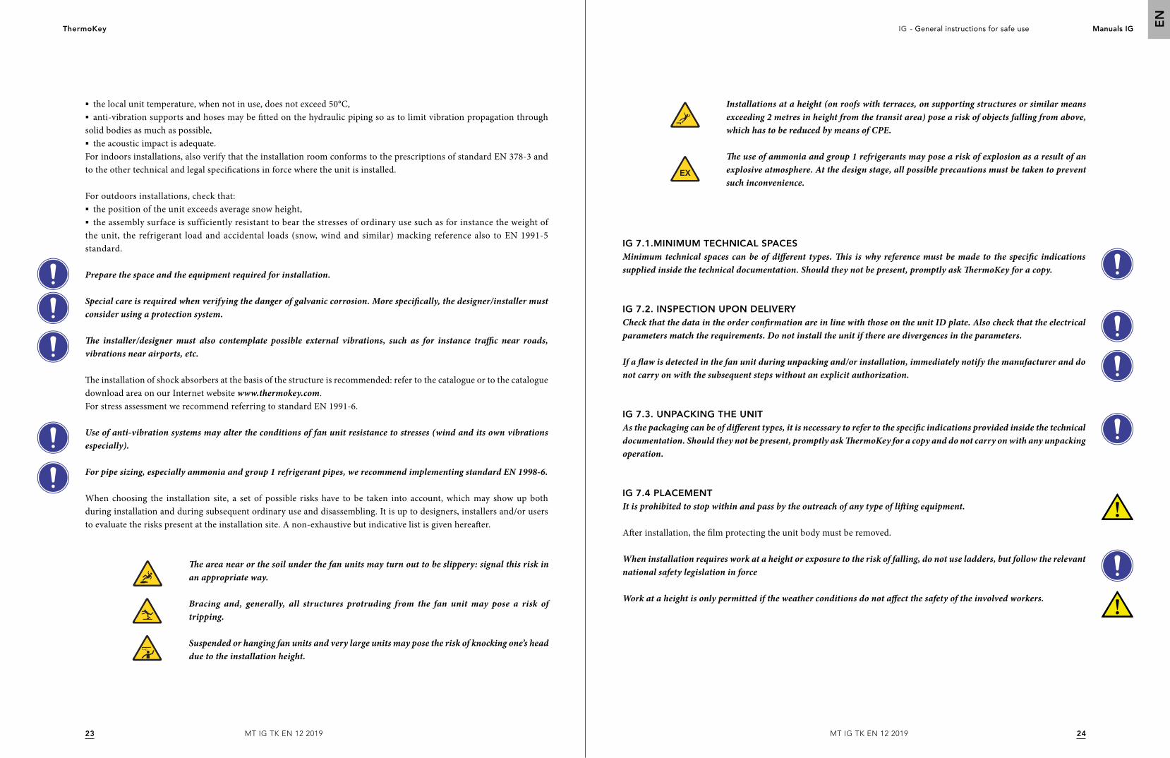
The area near or the soil under the fan units may turn out to be slippery: signal this risk in an appropriate way.
Bracing and, generally, all structures protruding from the fan unit may pose a risk of tripping.
Suspended or hanging fan units and very large units may pose the risk of knocking one’s head due to the installation height.
Installations at a height (on roofs with terraces, on supporting structures or similar means exceeding 2 metres in height from the transit area) pose a risk of objects falling from above, which has to be reduced by means of CPE.
The use of ammonia and group 1 refrigerants may pose a risk of explosion as a result of an explosive atmosphere. At the design stage, all possible precautions must be taken to prevent such inconvenience.
IG 7.1.MINIMUM TECHNICAL SPACESMinimum technical spaces can be of different types. This is why reference must be made to the specific indications supplied inside the technical documentation. Should they not be present, promptly ask ThermoKey for a copy.
IG 7.2. INSPECTION UPON DELIVERYCheck that the data in the order confirmation are in line with those on the unit ID plate. Also check that the electrical parameters match the requirements. Do not install the unit if there are divergences in the parameters.
If a flaw is detected in the fan unit during unpacking and/or installation, immediately notify the manufacturer and do not carry on with the subsequent steps without an explicit authorization.
IG 7.3. UNPACKING THE UNITAs the packaging can be of different types, it is necessary to refer to the specific indications provided inside the technical documentation. Should they not be present, promptly ask ThermoKey for a copy and do not carry on with any unpacking operation.
IG 7.4 PLACEMENTIt is prohibited to stop within and pass by the outreach of any type of lifting equipment.
After installation, the film protecting the unit body must be removed.
When installation requires work at a height or exposure to the risk of falling, do not use ladders, but follow the relevant national safety legislation in force
Work at a height is only permitted if the weather conditions do not affect the safety of the involved workers.
MT IG TK EN 12 2019MT IG TK EN 12 2019
ThermoKey IG - General instructions for safe use Manuals IG
2625
EN
IG 8. InstallationInstallation is the stage that follows fan unit placement, during which operations are performed to secure the unit to its support, bracing is placed, and parts likely to have been disassembled during handling are reassembled.
Installation has to be performed in conformity to the indications given in the manual and those provided in standard EN 378-3.
Mounting of the mechanical parts of the fan unit is to be carried out by the installer. The fan unit is equipped with mounting holes. Should the holes be too small in size, do not expand them without prior authorisation from ThermoKey.
The diameters of the mounting holes are the result of the manufacturer static calculations. The mounting elements have to take into account hole diameters.Mounting elements have to be equipped with all suitable means to prevent coming loose.
To size the anchoring or mounting devices of the fan units, follow the ETAG standards and refer to the technical catalogues published in the catalogue download area of our Internet website: www.thermokey.com.
For enhanced stability of the units installed outdoors against wind load, bracing may be fitted. The installer is in charge of selecting and sizing the bracing.
IG 9. Refrigeration and hydraulic connectionsIt is strictly prohibited to place the headers according to the intake line, as they must not be moved away from their original position.
§ When setting the joints of the IN/OUT piping, it is mandatory to check the gauge showing the refrigerant flow, which is fitted at the manifolds or flanges. § Installation of upstream shut-off valves is recommended for easier maintenance. If installation of these valves creates risks, it
is always up to the installer to foresee appropriate solutions for the circuit.§ For V-type condensers and dry coolers equipped with adiabatic systems, it is mandatory to drain water from the
feeding system to prevent ice formation whenever the ambient temperature is expected to drop below 0°C.§ For the connections of the refrigerating and hydraulic circuits, it is obligatory to comply with the diameters of the
existing attachments. Any kind of modification has to be agreed beforehand with the Customer Service of ThermoKey Spa, otherwise the manufacturer shall be relieved from all liability for harm to people and/or animals or damage to property, and for poorer performances than those declared. In such case, the Guarantee Conditions too shall no longer apply.
IG 9.1. HYDRAULIC CONNECTIONSHydraulic connections have to be set up in conformity with national or local legislation. The piping can be made of steel, zinc-coated steel or P.V.C. Pipes have to be accurately sized depending on the nominal refrigerant flow rate, pressure, pressure losses from the hydraulic circuit and the operating temperatures. All hydraulic connections have to be insulated by using appropriately thick, closed-cell material.
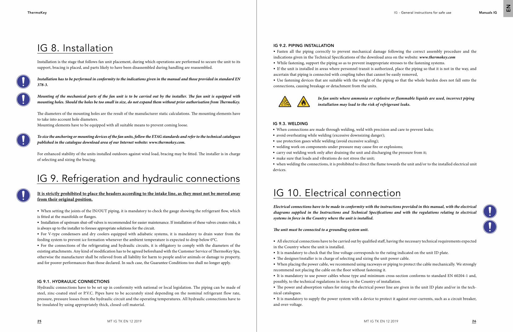
IG 9.2. PIPING INSTALLATION§ Fasten all the piping correctly to prevent mechanical damage following the correct assembly procedure and the
indications given in the Technical Specifications of the download area on the website: www.thermokey.com§ While fastening, support the piping so as to prevent inappropriate stresses to the fastening systems.§ If the unit is installed in areas where personnel transit is authorized, place the piping so that it is not in the way, and
ascertain that piping is connected with coupling tubes that cannot be easily removed,§ Use fastening devices that are suitable with the weight of the piping so that the whole burden does not fall onto the
connections, causing breakage or detachment from the units.
In fan units where ammonia or explosive or flammable liquids are used, incorrect piping installation may lead to the risk of refrigerant leaks.
IG 9.3. WELDING§ When connections are made through welding, weld with precision and care to prevent leaks;§ avoid overheating while welding (excessive downsizing danger);§ use protection gases while welding (avoid excessive scaling);§ welding work on components under pressure may cause fire or explosions;§ carry out welding work only after draining the unit and discharging the pressure from it;§ make sure that loads and vibrations do not stress the unit;§ when welding the connections, it is prohibited to direct the flame towards the unit and/or to the installed electrical unit
devices.
IG 10. Electrical connectionElectrical connections have to be made in conformity with the instructions provided in this manual, with the electrical diagrams supplied in the Instructions and Technical Specifications and with the regulations relating to electrical systems in force in the Country where the unit is installed.
The unit must be connected to a grounding system unit.
§ All electrical connections have to be carried out by qualified staff, having the necessary technical requirements expected in the Country where the unit is installed.§ It is mandatory to check that the line voltage corresponds to the rating indicated on the unit ID plate.§ The designer/installer is in charge of selecting and sizing the unit power cable.§ When placing the power cable, we recommend using raceways or piping to protect the cable mechanically. We strongly
recommend not placing the cable on the floor without fastening it.§ It is mandatory to use power cables whose type and minimum cross-section conforms to standard EN 60204-1 and,
possibly, to the technical regulations in force in the Country of installation.§ The power and absorption values for sizing the electrical power line are given in the unit ID plate and/or in the tech-
nical catalogues.§ It is mandatory to supply the power system with a device to protect it against over-currents, such as a circuit breaker,
and over-voltage.
MT IG TK EN 12 2019MT IG TK EN 12 2019
ThermoKey IG - General instructions for safe use Manuals IG
2827
EN
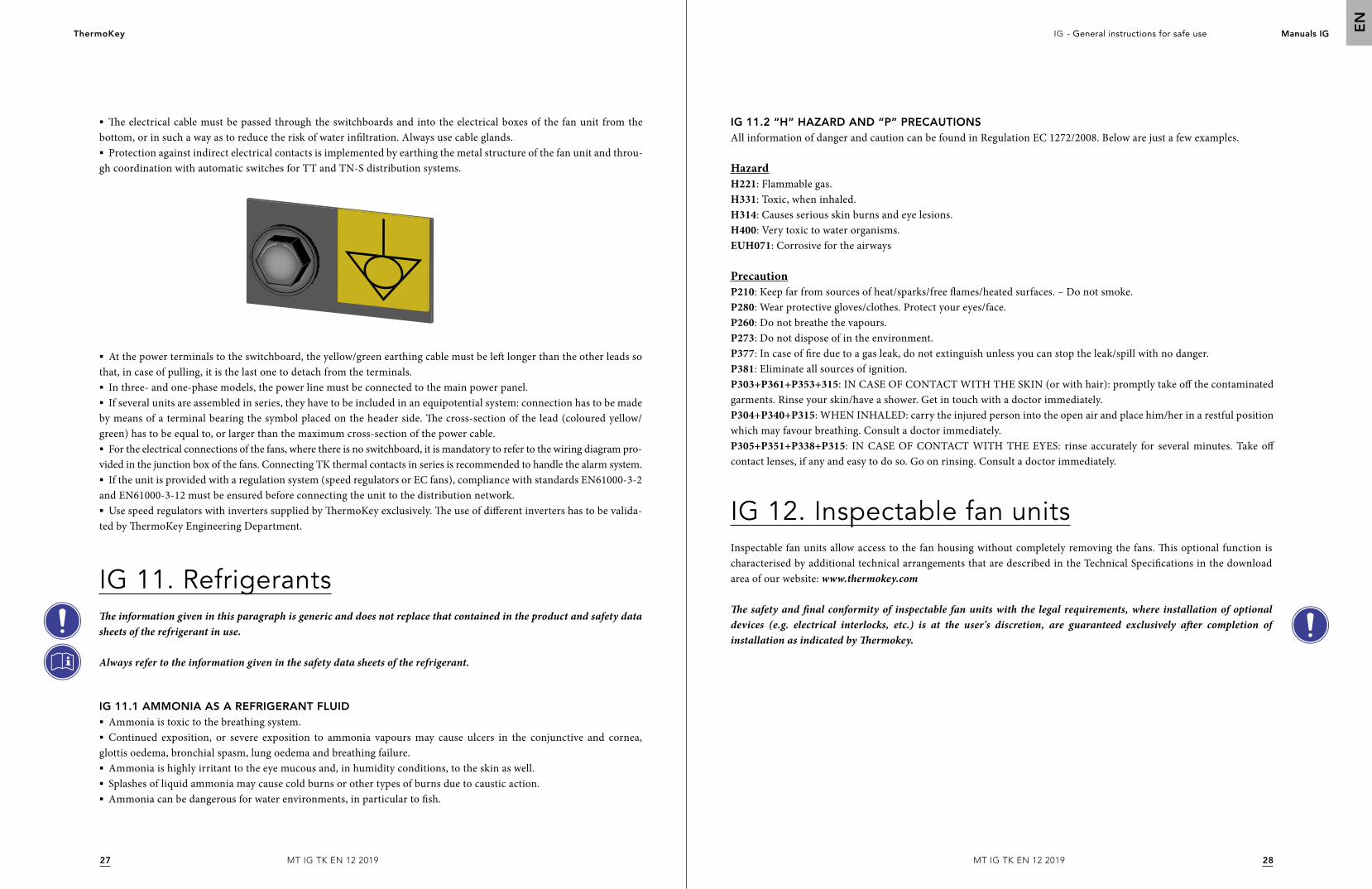
§ The electrical cable must be passed through the switchboards and into the electrical boxes of the fan unit from the bottom, or in such a way as to reduce the risk of water infiltration. Always use cable glands.§ Protection against indirect electrical contacts is implemented by earthing the metal structure of the fan unit and throu-
gh coordination with automatic switches for TT and TN-S distribution systems.
IG 11. RefrigerantsThe information given in this paragraph is generic and does not replace that contained in the product and safety data sheets of the refrigerant in use.
Always refer to the information given in the safety data sheets of the refrigerant.
IG 11.1 AMMONIA AS A REFRIGERANT FLUID§ Ammonia is toxic to the breathing system.§ Continued exposition, or severe exposition to ammonia vapours may cause ulcers in the conjunctive and cornea,
glottis oedema, bronchial spasm, lung oedema and breathing failure.§ Ammonia is highly irritant to the eye mucous and, in humidity conditions, to the skin as well.§ Splashes of liquid ammonia may cause cold burns or other types of burns due to caustic action.§ Ammonia can be dangerous for water environments, in particular to fish.
IG 12. Inspectable fan unitsInspectable fan units allow access to the fan housing without completely removing the fans. This optional function is characterised by additional technical arrangements that are described in the Technical Specifications in the download area of our website: www.thermokey.com
The safety and final conformity of inspectable fan units with the legal requirements, where installation of optional devices (e.g. electrical interlocks, etc.) is at the user's discretion, are guaranteed exclusively after completion of installation as indicated by Thermokey.
IG 11.2 “H” HAZARD AND “P” PRECAUTIONSAll information of danger and caution can be found in Regulation EC 1272/2008. Below are just a few examples.
HazardH221: Flammable gas. H331: Toxic, when inhaled. H314: Causes serious skin burns and eye lesions. H400: Very toxic to water organisms. EUH071: Corrosive for the airways PrecautionP210: Keep far from sources of heat/sparks/free flames/heated surfaces. – Do not smoke.P280: Wear protective gloves/clothes. Protect your eyes/face. P260: Do not breathe the vapours. P273: Do not dispose of in the environment. P377: In case of fire due to a gas leak, do not extinguish unless you can stop the leak/spill with no danger.P381: Eliminate all sources of ignition. P303+P361+P353+315: IN CASE OF CONTACT WITH THE SKIN (or with hair): promptly take off the contaminated garments. Rinse your skin/have a shower. Get in touch with a doctor immediately. P304+P340+P315: WHEN INHALED: carry the injured person into the open air and place him/her in a restful position which may favour breathing. Consult a doctor immediately. P305+P351+P338+P315: IN CASE OF CONTACT WITH THE EYES: rinse accurately for several minutes. Take off contact lenses, if any and easy to do so. Go on rinsing. Consult a doctor immediately.
§ At the power terminals to the switchboard, the yellow/green earthing cable must be left longer than the other leads so that, in case of pulling, it is the last one to detach from the terminals.§ In three- and one-phase models, the power line must be connected to the main power panel.§ If several units are assembled in series, they have to be included in an equipotential system: connection has to be made
by means of a terminal bearing the symbol placed on the header side. The cross-section of the lead (coloured yellow/green) has to be equal to, or larger than the maximum cross-section of the power cable.§ For the electrical connections of the fans, where there is no switchboard, it is mandatory to refer to the wiring diagram pro-
vided in the junction box of the fans. Connecting TK thermal contacts in series is recommended to handle the alarm system.§ If the unit is provided with a regulation system (speed regulators or EC fans), compliance with standards EN61000-3-2
and EN61000-3-12 must be ensured before connecting the unit to the distribution network.§ Use speed regulators with inverters supplied by ThermoKey exclusively. The use of different inverters has to be valida-
ted by ThermoKey Engineering Department.
Istruzioni generaliper un uso sicuro
Sistema di Gestione Qualita' ISO 9001
Sistema di Gestione Ambiente ISO 14001
Sistema di Gestione Sicurezza e Salute sul
posto di lavoro BS OHSAS 18001
MT IG TK IT 12 2019
LA VERSIONE ORIGINALE DELLE PRESENTI ISTRUZIONI È IN LINGUA ITALIANA
IT
3130
Heat Exchange SolutionsThermoKey IG - Istruzioni generali per un uso sicuro Manuali IG
IT
MT IG TK IT 12 2019MT IG TK IT 12 2019
LEGGERE ATTENTAMENTE E COMPRENDERE COMPLETAMENTE TUTTE LE INFORMAZIONI CONTENUTE IN QUESTE ISTRUZIONI PRIMA DELLA PROGETTAZIONE ED IN OGNI CASO PRIMA DI EFFETTUARE QUALUNQUE OPERAZIONE DI MOVIMENTAZIONE, DISIMBALLAGGIO, MONTAGGIO, POSIZIONAMENTO E MESSA IN ESERCIZIO DELL’APPARECCHIO.
ThermoKey declina ogni responsabilità per danni a persone o cose derivanti dalla mancata osservanza delle indicazioni contenute nel presente documento.
L’originale del presente manuale è in italiano , ed è reperibile sul sito internet: www.thermokey.comLa traduzione in inglese è conforme all’originale ed è reperibile sul sito internet: www.thermokey.comLe traduzioni in altre lingue possono contenere errori; in caso di dubbio fare sempre riferimento alla versione originale in italiano od alla sua traduzione in inglese.
Heat Exchange SolutionsThermoKey
LA FILOSOFIA DEL MANUALE
Il commento n. 255 delle linea guida applicative revisione 2 della direttiva macchine 2006/42/CE suggerisce di mettere a disposizione un formato elettronico reperibile su internet delle istruzioni per evitare il loro smarrimento e favorirne l'aggiornamento.Inoltre il commento 275 impone che vi sia corrispondenza fra le pubblicazioni tecnico-commerciali, quali i cataloghi, ed il manuale.Molte delle unità ventilate prodotte da ThermoKey sono personalizzate per uno specifico impianto o cliente.Sulla base dei punti sopra indicati e considerando che gli utilizzatori delle istruzioni sono i progettisti degli impianti, gli installatori ed infine gli utilizzatori, la documentazione tecnica per la corretta progettazione ed il corretto uso dell'unità ventilata segue la filosofia di comporsi di una serie di documenti che, nel loro insieme, vengono appunto definiti MANUALE.
ISTRUZIONI GENERALI PER UN USO SICURO (IG)
ISTRUZIONI PER LA MOVIMENTAZIONE ED IL DISIMBALLO (IM)
ISTRUZIONI E DATI TECNICI (TC)
ISTRUZIONI SPECIFICHE D'USO E MANUTENZIONE (IS)
CONTENUTO DEL MANUALE
3332
Heat Exchange SolutionsThermoKey IG - Istruzioni generali per un uso sicuro Manuali IG
IT
MT IG TK IT 12 2019MT IG TK IT 12 2019
Nelle Istruzioni Generali per un Uso Sicuro sono indicate le informazioni di sicurezza ed uso corretto comprendenti:
IG 1. NOTE PRELIMINARIIG 1.1 NOTE DEL SOFTWARE ARCHIMEDE
IG 2. NOTE LEGALIIG 2.1 VERSIONE ORIGINALE
IG 2.2 LIMITI D'USO DEL PRESENTE MANUALE
IG 2.3 CONTENUTO E COMPRENSIONE DEL MANUALE
IG 2.4 RESPONSABILITÀ
IG 2.5 NORME DI LEGGE E TECNICHE IMPIEGATE NELLA COSTRUZIONE DELL'UNITÀ
IG 2.6 IMPORTANZA DELLA SERIE DI NORME EN378
IG 3. TARGHE ED ETICHETTE GENERICHE
IG 4. AVVERTENZE GENERALI E NORME DI SICUREZZAIG 4.1 GENERALITÀ
IG 4.2 MOVIMENTAZIONE CARICO E SCARICO
IG 4.3 TRASPORTO
IG 4.4 IMMAGAZZINAMENTO
IG 4.5 ANNOTAZIONE PER I VENTILATORI
IG 4.6 SICUREZZA ELETTRICA
IG 4.7 SICUREZZA MECCANICA
IG 5. USI SCORRETTI E VIETATIIG 5.1 DIVIETI SPECIFICI PER LE UNITÀ VENTILATE AD AMMONIACA
IG 6. RISCHI RESIDUI GENERALIIG 6.1. PERICOLI E DPI DI SICUREZZA
IG 6.2 PERDITE DI AMMONIACA
IG 6.3 ISTRUZIONI PER IL TRATTAMENTO DELLE FERITE
IG 7. POSIZIONAMENTO – NOTE GENERALI E COMUNIIG 7.1 SPAZI TECNICI MINIMI
IG 7.2 ISPEZONE ALLA CONSEGNA
IG 7.3 DISIMBALLO DELL'UNITÀ
IG 7.4 COLLOCAZIONE
IG 8. INSTALLAZIONE
IG 9. ATTACCHI FRIGORIFERI ED IDRICIIG 9.1 COLLEGAMENTI IDRAULICI
IG 9.2 MONTAGGIO DELLE TUBAZIONI
IG 9.3 SALDATURA
IG 10. COLLEGAMENTO ELETTRICO
INDICE
3435
3636
36
36
38
40
40
40
4040
41
41
41
42
42
42
4344
4444
47
47
4749
49
49
49
50
5050
51
51
51
§ Nelle Istruzioni di Movimentazione e Disimballo sono indicate, mediante figure numerate, le operazioni necessarie e consentite per la movimentazione ed il disimballaggio delle varie unità ventilate. Nel caso di unità ventilate speciali le informazioni corrette saranno identificate nel documento dal numero di conferma d'ordine.
Per facilitare l'aggiornamento e la non ambiguità di informazioni, questa parte della documentazione dell'unità ventilata è costituita da cataloghi ed altra documentazione tecnica fornita direttamente da ThermoKey e/o reperibile sul sito internet www.thermokey.com.
§ Nel capitolo TC Istruzioni e Dati Tecnici sono riportate le informazioni tecniche rilevanti per ogni singola tipologia di unità ventilata, raggruppate in famiglie e comprendono:
- DIMENSIONI E PESI
- INGOMBRI E SPAZI TECNICI MINIMI
- DATI AERAULICI, PRESTAZIONALI ED ELETTRICI
- IL LIVELLO DI EMISSIONI SONORE
- SCHEMI ELETTRICI
- BOLLETTINO TECNICO
§ Le Istruzioni Specifiche per l'Uso e la Manutenzione sono una parte specifica per ogni modello ed eventualmente per ogni unità ventilata specifica e comprendono:
IS 1 - ISTRUZIONI DI FUNZIONAMENTO
IS 2 - PROBLEMI DI FUNZIONAMENTO
IS 3 - MANUTENZIONE
IS 4 - PARTI DI RICAMBIO
IG 11. REFRIGERANTIIG 11.1 AMMONIACA COME FLUIDO REFRIGERANTE
IG 11.2 INDICAZIONI DI PERICOLO H E PRUDENZA P
IG 12. UNITÀ VENTILATE ISPEZIONABILI
5252
53
53
3534
Heat Exchange SolutionsThermoKey IG - Istruzioni generali per un uso sicuro Manuali IG
IT
MT IG TK IT 12 2019MT IG TK IT 12 2019
IG 1. Note preliminariL'UNITÀ DOVRÀ ESSERE DESTINATA SOLO ALL'USO PER LA QUALE È STATA ESPRESSAMENTE CONCEPITA, RIPORTATO AL PARAGRAFO "NOTE PRELIMINARI"
1. Le note preliminari sono una parte essenziale del manuale e devono pertanto essere lette con grande attenzione e comprese.
2. Il presente manuale è una parte della documentazione tecnica dell'unità ventilata. Il presente manuale può venir integrato da altre indicazioni ed in parte modificato in funzione di personalizzazioni o condizioni operative fuori standard. In termini generali il manuale si compone di una parte principale e di alcuni allegati tecnici. Nel seguito per semplicità ci si riferirà, dove non altrimenti specificato, al manuale intendendo tutta la documentazione tecnica necessaria al corretto uso dell'unità ventilata.
3. Conservare il presente manuale per tutta la vita utile dell'unità ventilata.
4. Prestare particolare attenzione alle norme d’uso presenti nel manuale in quanto la mancata osservazione può causare danno all'unità ventilata e/o a persone, animali, cose.
5. ThermoKey si riserva il diritto di modificare il presente manuale in ogni momento; le revisioni nella loro forma ultima sono sempre rese pubbliche sul sito www.thermokey.com. Per verificare se siete in possesso dell'ultima revisione dovete consultare l'indice di revisione.
6. I dati del costruttore ed il riferimento al numero d'ordine del cliente sono riportati sulla targa identificativa dell'unità ventilata che contiene, oltre ai dati dell'unità ventilata stessa, il numero d'ordine.
7. I ricambi non originali devono essere preventivamente approvati da ThermoKey.
8. L'unità ventilata è conforme ai Requisiti Essenziali di Salute e Sicurezza della direttiva 2006/42/CE applicabili per quanto previsto nelle condizioni d'impiego standard o concordate con il cliente.
9. Sono esplicitamente vietati tutti gli usi non previsti e descritti nel presente manuale e/o che non siano stati concordati fra utilizzatore e ThermoKey preventivamente alla costruzione/messa in servizio dell'unità ventilata. Gli usi impropri dell'unità ventilata possono provocare condizioni pericolose sulle cui conseguenze ThermoKey non si assume nessuna responsabilità.
10. L'unità ventilata è stata prevista per essere impiegata solo con i refrigeranti indicati nell'ordine identificato con il numero riportato sulla targa identificativa.
11. E' vietato l'impiego di fluidi refrigeranti differenti da quelli esplicitamente indicati.
12. Per l'impiego di ammoniaca e refrigeranti del gruppo 1 possono essere necessarie ulteriori prescrizioni ed indicazioni d'uso rispetto a quelle riportate nelle presenti istruzioni ma che in ogni caso sono contenute nel manuale dell'unità ventilata.
Il riferimento al numero d'ordine è molto importante perchè identifica le eventuali personalizzazioni e limitazioni d'uso concordate fra ThermoKey quale costruttore ed il committente quale utilizzatore.
13. È vietato l'uso di sostanze e fluidi che possono deteriorare, rendere insicuro o diminuire le prestazioni dell'unità ventilata.
14. Tutti i dati tecnici delle unità ventilate e tutti i limiti d'uso e le caratteristiche minime che deve possedere il sito di installazione sono presenti sui cataloghi tecnici.
15. Qualora si rendessero necessarie modifiche o variazione all'unità ventilata dopo la sua costruzione ma prima della sua messa in servizio oppure se le condizioni operative del sito di installazione non fossero quelle previste od in ogni caso in cui vi fosse una differenza fra quanto previsto prima della costruzione e lo stato di fatto del sito di installazione, ThermoKey deve essere contattata immediatamente e certamente prima di eseguire qualsiasi intervento di modifica. In caso contrario nessuna responsabilità potrà essere posta in capo a ThermoKey.
16. Viene demandato al progettista, all'installatore e/o all'utilizzatore l'osservanza di norme e regolamenti locali in relazione all'installazione, impiego e smaltimento dell'unità ventilata.
17. Per personale qualificato, ove non meglio specificato nel presente manuale, si deve sempre intendere una persona adeguatamente informata o sorvegliata da persona con formazione, conoscenza ed esperienza tali da saper eseguire il lavoro a regola d'arte e consentirgli di percepire rischi ed evitare pericoli che ne possono derivare.
18. Per le condizioni di garanzia fare riferimento agli accordi presi in fase d'ordine.
19. È vietata la riproduzione totale o parziale del presente manuale senza l’autorizzazione scritta del costruttore. Copie aggiornate del presente manuale sono reperibili nel sito www.thermokey.com
IG 1.1. NOTE DEL SOFTWARE ARCHIMEDE1. La tensione è riferita ai dati nominali del fornitore : il consumo dei ventilatori può variare al variare della temperatura aria e del sistema di voltaggio.
2. L'unità potrebbe non essere adatta per ambienti molto corrosivi. Per applicazioni speciali contattare ThermoKey.In caso di selezione di materiali alette speciali (rame,verniciato), tutti gli altri materiali dell'unità rimangono standard (per informazioni dettagliate consultare la descrizione tecnica dell'apparecchio).
3. Dimensioni e pesi non sono validi per tutte le possibili opzioni!Le dimensioni fuoritutto della scheda sono per unità senza regolazione/quadri elettrici(Per informazioni piu dettagliate fare riferimento al Electrical box Manual).Nel caso di unità a flusso aria orizzontale la posizione standard degli attacchi è sx guardando pacco alettato.
4. Il rumore causato dai sistemi di controllo, sistema adiabatico..etc non è considerato nella dichiarazione di rumore delle ventole.I valori reali possono subire anche deviazioni dovuti alle condizioni dell'installazione.
5. Il manuale è costituito da 4 parti IG = Istruzioni generali,IM = Istruzioni di movimentazione e disimballo,TC = Istruzioni e dati tecnici,IS = Istruzioni specifiche d'uso e manutenzione. Se non espressamente richiesto in fase d'ordine,le istruzioni TC e IS devo essere scaricate dall'utilizzatore dal sito www.thermokey.com e non saranno fornite in formato cartaceo. L'installatore è tenuto ad attenersi alle indicazioni dei manuali sopra riportati e tutti i manuali delle principali componentistiche elettriche (ad es. ventilatori, pompe, regolatori...).
6. L’unità è equipaggiata con ventilatori che rispondono ai requisiti di efficienza della direttiva ERP 2009/125/EC.
7. Conformemente alla norma EN 13487 il livello di pressione sonora dichiarato per la presente unità è stato calcolato in condizioni di campo libero su un piano riflettente con superficie di riferimento a parallelepipedo.Con riferimento
3736
Heat Exchange SolutionsThermoKey IG - Istruzioni generali per un uso sicuro Manuali IG
IT
MT IG TK IT 12 2019MT IG TK IT 12 2019
IG 2. Note legaliIG 2.1. VERSIONE ORIGINALELa versione originale del presente manuale è in lingua italiana ed accompagna ogni traduzione ufficiale del manuale. Le traduzioni del manuale non autorizzate dal fabbricante non sono ritenute in corso di validità.
L'uso di copie e/o traduzioni del presente manuale non autorizzate e/o l'impiego di traduzioni prive della versione originale in lingua italiana esonerano ThermoKey da qualsiasi conseguenza e responsabilità possibili in caso di incidente.
IG 2.2. LIMITI D’USO DEL PRESENTE MANUALEIl presente manuale d’uso e manutenzione è stato predisposto per le unità ventilate destinate al mercato Comunitario Europeo che si fregiano del marchio CE.
Il presente manuale d'uso e manutenzione non copre l'immissione sul mercato e/o l'impiego delle unità in Paesi non facenti parte dell'Unione Europea.
IG 2.3. CONTENUTO E COMPRENSIONE DEL MANUALEQualora il progettista, l’installatore e/o l’utilizzatore (in termini generali ed omnicomprensivi operatori) non reperissero nel presente manuale le informazioni tecniche necessarie all’installazione, all’uso, alla manutenzione e/o allo smaltimento sicuro dell’unità od avessero dei dubbi in relazione alle corrette modalità di installazione, d’uso, di manutenzione e/o di smaltimento sono esortati a mettersi in contatto con ThermoKey; il presente manuale d’uso e manutenzione è redatto per essere il più possibile completo e chiaro, in relazione alla preparazione ed alle competenze dei suoi utilizzatori.La mancata comprensione del contenuto del presente manuale o la incompleta comprensione delle sue indicazioni sono una condizione sufficiente per interrompere immediatamente qualsiasi fase di progettazione, installazione, uso, manutenzione e/o smaltimento dell’unità stessa.
alla norma ISO 3744 ,quando la differenza di misura tra macchina attiva e disattiva è <= 6dB(A) ,la misura sonora non raggiunge la precisione prevista della norma. Valori di rumore di fondo inferiori ai 30dB(A) sono tipici di ambienti interni e silenziosi. La dichiarazione della pressione sonora della macchina,dichiarata sulle schede tecniche ThermoKey, considera trascurabile il rumore di fondo.
8. S x x x x : codice seriale identificativo della combinazione delle opzioni standard selezionabili su Archimede (elencate e descritte nella sezione ACCESSORI) e speciali a richiesta. Il codice viene visualizzato sulla conferma d'ordine (come parte integrante del codice di descrizione modello) ed è presente sull'etichetta dati tecnici di prodotto. Nota: Per ogni gamma le opzioni disponibili sono elencate a catalogo sulla Tabella Opzioni ed Accessori. Il registro delle combinazioni delle opzioni associate al codice S x x x x è consultabile a richiesta.
9. La consegna di unità standard è considerata ex works.Per condizioni o termini speciali(ex. Grandi quantità,specifiche speciali..) per favore contattare Sales dept.
10. L'unità standard non è autodrenante:la scelta del fluido (acqua/glicole) è in stretta relazione con il punto di congelamento dello stesso e dell'effettivo periodo di funzionamento dell' unità.Per costruzione autodrenante contattare ThermoKey per offerte dedicate.
11. La freccia dell'aria dichiarata è la distanza dal ventilatore ove la velocità dell'aria risulta essere 0.25 m/s. La freccia dell'aria è definita ai valori di default del ventilatore: per gli aeroevaporatori Cubici, Light Cubic, modelli commerciali con collegamento a Delta e Stella, per Doppio Flusso con connessione definito dalla serie.
12. Il dimensionamento è effettuato attraverso una simulazione del programma di selezione che non prende in considerazione l'influenza delle condizioni di installazione.
13. Nella scelta della massima pressione operativa,viene considerata la pressione associata alla temperatura di condensazione middle point
14. Per unità ventilate con batterie microcanale,è tassattivo attenersi alle procedure presenti sul sito ThermoKey (Indications for the use of TK micro cores).
15. Gruppo dei fluidi relativo alla direttiva 2014/68/CE.
16. I dati riportati nell’etichetta dei ventilatori non rappresentano la condizione peggiore di assorbimento.
17. Le performances dichiarate sono adeguate ad applicazioni HVAC,con flusso aria in campo libero sia lato batteria che lato ventilatore (e.g. evitare ricircoli o qualsiasi elemento che riduca la portata d’aria) e con temperature ingresso batteria uniformi (e.g. evitare condizioni che elementi adiacenti comportino variazioni di temperature all’ingresso unità).Per applicazioni critiche (ad esempio industriali,power…etc) contattare ThermoKey.
18. ThermoKey si riserva di modificare in qualsiasi momento,senza preavviso,i dati tecnici,i disegni e i prezzi del software Archimede.Consultare la release del software e l'EULA del software direttamente nella sezione "?".
19. Il software Archimede si basa sulle librerie di olii,refrigeranti e miscele più recenti di Refprop. L’aggiornamento dei dati può comportare performances delle unità differenti dalle releases di Archimede passate.
20. Attenzione, le dimensioni fuoritutto ed il peso dell'unità allestite con sistema EPS, indicate nella scheda tecnica, sono relative al modello senza parte elettrica e pannelli evaporativi montati, per le variazioni dei valori delle possibili combinazioni di opzione fare riferimento alle seguenti indicazioni!
Considerare che i moduli evaporativi montati sul fianco del modello hanno una sporgenza di 440mm totali sulla larghezza rispetto all'ingombro del modello, mentre non eccedono sulle dimensioni di lunghezza ed altezza del modello, inoltre i tubi di scarico montati sui moduli sporgono ulteriormente di 320mm totali sulla larghezza del modello. Considerare che i quadri elettrici e il piping di allacciamento sporgono a seconda delle combinazioni selezionate e richieste di 400mm dalle testate del modello.Per le dimensioni specifiche fare riferimento al disegno di conferma d'ordine.Considerare il peso operativo dei moduli evaporativi montati con pannelli bagnati di 60kg a modulo (per ventilatore). Fare attenzione che nel caso di una non ottimale manutenzione delle vaschette di scarico o della linea di scarico, considerare un possibile accumulo d'acqua nella vaschetta e nelle sole tubazioni di scarico del sistema EPS di circa 30kg a modulo (per ventilatore).Considerare il peso del piping di allacciamento del sistema EPS alla rete idrica premontato sul modello di circa 25kg ad unità. Considerare il peso dell'eventuale quadro elettrico di controllo del sistema EPS premontato sul modello di circa 35kg ad unità.
3938
Heat Exchange SolutionsThermoKey IG - Istruzioni generali per un uso sicuro Manuali IG
IT
MT IG TK IT 12 2019MT IG TK IT 12 2019
Qualora gli operatori persistessero nella loro attività senza aver compreso perfettamente e completamente il presente manuale d'uso e manutenzione e/o senza essere in possesso di tutte le conoscenze e le indicazioni necessarie allo svolgimento delle loro attività, ThermoKey si ritiene esonerata da qualsiasi conseguenza e responsabilità.
ThermoKey considera negliegenza la mancata segnalazione di un qualsivoglia errore, omissione, refuso, incongruenza etcetera del presente manuale in relazione alle istruzioni ed alle indicazioni tecniche: il progettista, l’installatore e l’utilizzatore (manutentori) devono prontamente segnalare a ThermoKey situazioni che potrebbero portare ad una riduzione della sicurezza delle persone, delle cose e dell’ambiente agendo con la competenza, la professionalità, lo spirito collaborativo e la diligenza necessari.
Qualsiasi comportamento negligente, poco accorto od indice di scarsa competenza tecnico-professionale esonera il fabbricante da qualsiasi conseguenze e responsabilità possibili.
IG 2.4. RESPONSABILITÀResponsabilità del fabbricanteIl fabbricante è responsabile della progettazione, costruzione, collaudo ed imballo dell'unità ventilata al fine dell’immissione nel mercato dell'Unione Europea. Il fabbricante garantisce che l'unità ventilata è progettata, costruita, collaudata ed imballata nel rispetto dei requisiti essenziali fissati nelle direttive comunitarie applicabili e che è stata eseguita una opportuna valutazione di conformità in tal senso.Le fasi di rimozione dell’imballo, installazione, messa in servizio, manutenzione, smontaggio e smaltimento non sono a carico del fabbricante il quale nelle presenti istruzioni fornisce il maggior numero possibile di informazioni utili per le citate fasi di vita dell'unità ventilata.Tutte le parti dell’unità sono state progettate, realizzate e collaudate in modo da poter sopportare le sollecitazioni ragionevolmente prevedibili nell’uso previsto ed in quello ragionevolmente prevedibile: nessuna garanzia di sicurezza e/o funzionamento può essere data se le unità vengono impiegate in condizioni d'uso non esplicitamente previste da ThermoKey e quindi vietate.
L'installazione, l'uso, la manutenzione e/o lo smaltimento dell'apparecchiatura in condizioni vietate, non previste e/o comunque diverse da quelle previste da ThermoKey, la esonerano da qualsiasi conseguenza e responsabilità possibili.
Responsabilità del progettista e dell’installatoreL’installatore e/o il progettista hanno l’obbligo di valutare i rischi, predisporre mezzi e sistemi di emergenza, allarme, segnalazione e protezione ed inoltre devono predisporre le istruzioni complessive dell’impianto/sistema di refrigerazione del quale fa parte l'unità ventilata, come prescritto nella norma EN 378-4.E’ inoltre compito del progettista e/o dell’installatore determinare quali siano i mezzi e le modalità migliori e più sicure per la movimentazione ed eventualmente lo stoccaggio dell’unità al di fuori delle sedi e/o dei magazzini del fabbricante. In particolare ricade fra le responsabilità del progettista e/o dell’installatore verificare le prescrizioni fornite dal fabbricante ed imporne il rispetto nelle fasi di movimentazione, trasporto e stoccaggio.
L'errata valutazione dei rischi da parte del progettista e/o dell'installatore ovvero una scelta inadeguata dei mezzi e dei sistemi di emergenza, allarme, segnalazione e protezione esonerano ThermoKey da qualsiasi conseguenza e responsabilità possibili.
Il progettista è la figura che interviene nella fase di progettazione dell’impianto/sistema di refrigerazione nel quale l'unità ventilata viene installata ed ha responsabilità sia per l’aspetto prestazionale che per l’aspetto di sicurezza. Il progettista ha la responsabilità di scegliere i componenti più idonei per l’impianto che sta progettando, nei limiti d’uso che il fabbricante impone. La preparazione del progettista e le sue competenze devono essere sufficienti a comprendere in maniera chiara il contenuto del presente manuale d’uso e manutenzione e di ogni altro documento tecnico-commerciale relativo all’unità ed inoltre devono essere sufficienti a richiedere eventuali chiarimenti al fabbricante nell’ottica di realizzare un impianto/sistema funzionale, sicuro ed a regola d’arte. In particolare il progettista deve essere in grado di individuare le condizioni di lavoro ragionevolmente prevedibili dell’unità (ambientali, di fissaggio, di carichi e sollecitazioni, di collegamento agli impianti elettrico, fluidico, idraulico ecc) e verificare che l’unità sia idonea a tali condizioni.
Un'errata identificazione delle condizioni di lavoro dell'unità ventilata da parte del progettista esonera ThermoKey da qualsiasi conseguenza e responsabilità.
Se il progetto viene suddiviso in più parti, il coordinatore della progettazione, chiunque esso sia, sarà considerato quale progettista. L’installatore è la figura che interviene nella posa in opera e nella realizzazione dell’impianto, in conformità alle indicazioni progettuali, alle specifiche dei componenti così come definite dai loro fabbricanti ed alla regola dell’arte. La preparazione dell'installatore e le sue competenze devono essere sufficienti a comprendere in maniera chiara il contenuto del presente manuale d’uso e manutenzione e di ogni altro documento tecnico-commerciale relativo all’unità ed inoltre deve essere sufficiente a richiedere eventuali chiarimenti al fabbricante nell’ottica di realizzare un impianto/sistema funzionale, sicuro ed a regola d’arte.
Il personale che interviene nelle varie fasi di installazione e messa in servizio dell'unità deve essere competente e formato. Per quanto di pertinenza, il livello minimo che deve essere garantito è quello indicato nella EN 13313.
Se l’installazione viene suddivisa in più parti, il coordinatore dell’installazione, chiunque esso sia, sarà considerato quale installatore.
Responsabilità del conduttore dell’impianto/sistema di refrigerazioneIl conduttore è la figura che impiega l’impianto e quindi l’unità oggetto del presente manuale d’uso e manutenzione. Il conduttore ha la responsabilità della manutenzione dell’unità.
Il personale che interviene nelle varie fasi di installazione e messa in servizio dell'unità deve essere competente e formato. Per quanto di pertinenza, il livello minimo che deve essere garantito è quello indicato nella EN 13313.
Il conduttore ha l’obbligo di impiegare solo personale competente e formato, dotato dei necessari dispositivi di protezione individuale, nelle fasi di controllo, manutenzione, riparazione, emergenza e smaltimento dell’unità.
Si ricorda che la progettazione dell'impianto/sistema di refrigerazione non è in capo a ThermoKey che quindi è esonerato da qualsiasi conseguenza e/o responsabilità derivanti da errata progettazione/installazione .Si ricorda che le unità possono subire modifiche tecniche e/o aggiornamenti da parte del fabbricante ed è in capo al conduttore verificare la compatibilità fra l'impianto/sistema e la nuova versione dell'unità.
4140
Heat Exchange SolutionsThermoKey IG - Istruzioni generali per un uso sicuro Manuali IG
IT
MT IG TK IT 12 2019MT IG TK IT 12 2019
IG 2.5 NORME DI LEGGE E TECNICHE IMPIEGATE NELLA COSTRUZIONE DELL’UNITÀPer le norme impiegate dal fabbricante nella costruzione dell’unità si faccia sempre riferimento alla Dichiarazione ThermoKey inviata con l'unità stessa.
IG 2.6. IMPORTANZA DELLA SERIE DI NORME EN 378Le norme tecniche EN 378 costituiscono una serie di quattro norme tecniche (EN 378-1, EN 378-2, EN 378-3 ed EN 378-4) che rappresentano una fondamentale linea guida alla progettazione, installazione, conduzione, manutenzione e smaltimento degli impianti e delle relative apparecchiature di refrigerazione.Le norme della serie sono orientate a fornire una panoramica completa degli aspetti di sicurezza che devono essere presi in considerazione dai progettisti, dagli installatori, dai conduttori e dai manutentori degli impianti.ThermoKey considera fondamentali per la sicurezza delle persone, delle cose e dell’ambiente l’impiego delle norme del gruppo EN 378 in relazione all’impiego dell’unità oggetto del presente manuale in un impianto/sistema di refrigerazione.Il mancato rispetto delle prescrizioni delle norme può causare, principalmente e non limitatamente:§ o il pericolo di fuoriuscita od emissione del refrigerante, con conseguente incendio od esplosione e/o danno alla salute
delle persone, delle cose e dell’ambiente.§ o il rischio di infortuni nelle varie fasi di installazione, uso, manutenzione e smaltimento da parte delle persone
coinvolte nelle varie fasi.
IG 3. Targhe ed etichette genericheL’utilizzatore deve garantire che le etichette e le targhe applicate dal fabbricante sull’unità siano mantenute in buono stato di conservazione, leggibili e ben fissate. Se usurate, illeggibili od in ogni caso poco comprensibili etichette e targhe devono essere sostituite.
IG 4. Avvertenze generali e norme di sicurezzaIG 4.1. GENERALITÀ1. L'unità è prevista per un impiego automatico non sorvegliato.
2. Il progettista e/o l'installatore dovranno prevenire i colpi d'ariete.
3. I sistemi di fissaggio dell'unità sono a carico dell'utilizzatore che dovrà assicurarsi che siano progettati in conformità alle disposizioni ETAG pertinenti per il tipo di supporto.
4. Gli utilizzatori delle unità che impiegano fluidi pericolosi devono rispettare fedelmente le indicazioni delle schede di sicurezza del fluido.
5. L'aerazione del luogo di installazione dell'unità che impiegano fluidi potenzialmente esplosivi od infiammabili è essenziale: il progettista, l'installatore e/o l'utilizzatore devono farsene carico.
6. I ventilatori sono progettati per il funzionamento continuo S1 (funzionamento continuo a carico costante). Se i ventilatori vengono utilizzati con un sistema di regolazione ON/OFF, il comando non deve prevedere commutazioni troppo frequenti (si veda scheda tecnica del ventilatore).
7. Oltre alle presenti avvertenze riportate in questi capitoli, per ogni modello possono essere previste specifiche indicazioni (vedere sito ThermoKey http://www.thermokey.com/Manuali.aspx).
IG 4.2. MOVIMENTAZIONE, CARICO E SCARICO1. La movimentazione e la manovra durante le fasi di carico e scarico devono essere eseguite da personale qualificato dotato di mezzi idonei, in perfetta aderenza con le indicazioni del fabbricante.
2. In particolare gli addetti alla movimentazione dell’unità devono:- accertarsi che il mezzo di sollevamento a loro disposizione supporti il peso dell’unità con un congruo margine di sicurezza,- assicurarsi che non siano presenti persone nel raggio di azione del mezzo impiegato in fase di scarico e comunque nell’area dove si svolgono tali attività,- assicurarsi che l’unità venga agganciata, con ganci appositi, solo nei punti specificati dal fabbricante.
Il mancato rispetto di uno o più dei punti sopra indicati ed in generale una condotta che possa presentare dei rischi per le persone durante la movimentazione dell’unità esonera il fabbricante da qualsiasi conseguenza e responsabilità possibili.
Il mancato rispetto delle indicazioni sopra menzionate può causare danni alle persone quali:-schiacciamento- tranciamento degli arti
Inoltre può arrecare danni all’unità precludendone il corretto funzionamento.
IG 4.3. TRASPORTONel caso di trasporti via mare o via terra con particolari condizioni del fondo stradale (dissestato) è necessario rimuovere dalle unità ventilate tutte le parti che potrebbero danneggiarsi causando guasti e malfunzionamenti futuri o procedere ad imballaggi speciali.
L'operazione di smontaggio e rimontaggio devono essere eseguite solo a seguito di parere favorevole di ThermoKey e solo dietro sue dirette e precise istruzioni. Il mancato rispetto di questa indicazione esonera ThermoKey da ogni responsabilità futura.
IG 4.4. IMMAGAZZINAMENTOSe l’apparecchiatura deve essere stoccata prima dell’installazione (uno o più mesi) è bene prendere le seguenti precauzioni:§ lasciare l'unità ventilata nell’imballo originale fino al momento dell'installazione oppure ripristinare l’imballo in
maniera tale da garantire un equivalente livello di protezione all’imballo originale contro gli agenti atmosferici, la polvere e dagli insetti o piccoli roditori,§ riporre al coperto, con temperature comprese tra +15°C e +25ºC ed una percentuale di umidità compresa tra il 50%
ed il 70%,§ assicurarsi che l’unità non sia esposta a liquidi o vapori corrosivi,§ le unità non possono essere impilate l’una sull’altra durante l’immagazzinamento ed il trasporto, se non espressamente
previsto.
Il mancato rispetto delle indicazioni circa l'immagazzinamento manleva ThermoKey da qualsiasi danneggiamento conseguente ad una conservazione dell'unità ventilata non appropriata.
4342
Heat Exchange SolutionsThermoKey IG - Istruzioni generali per un uso sicuro Manuali IG
IT
MT IG TK IT 12 2019MT IG TK IT 12 2019
IG 4.5. ANNOTAZIONE PER I VENTILATORISe l’unità viene installata all’aperto ma non messa in servizio immediatamente, è consigliabile mettere in funzione il/I venti-latore/i almeno una volta alla settimana, per 4-6 ore, per evitare che i motori elettrici si danneggino.
IG 4.6. SICUREZZA ELETTRICA1. L’allacciamento elettrico, idrico e il collegamento delle unità di regolazione (optional) devono essere eseguiti esclusivamente da personale qualificato e in possesso dei requisiti previsti dalla legislazione del Paese dove verrà installato l’apparecchio.
2. L'unità è prevista per operare nei limiti di tensione, frequenza, corrente e condizioni di cortocircuito indicati nella sua targa.
3. Un dispositivo di sezionamento generale deve essere installato a monte della dorsale di alimentazione dall'utilizzatore. Questo dispositivo deve poter essere bloccato nella posizione di aperto (unità ventilata non alimentata) ad esempio per mezzo di un lucchetto.
4. L'unità può essere provvista di interuttori di servizio, che servono per la fase manutentiva. Su diverse ns unità, per poterli utilizzarli in fase di manutenzione, bisogna predisporre un sistema di accesso adeguato (come una impalcatura, un trabattello o altro mezzo di accesso al posto di lavoro) a carico del cliente. Questo è necessario, ad es. considerando unità Vtype, e unità a Tavola con telai supplementari o staffe non standard ThermoKey.
5. Deve essere prevista una sola connessione alla rete elettrica per l'unità. Se più connessioni sono necessarie, il progettista dell'impianto, l'installatore o l'utilizzatore dovranno prevedere mezzi di disconnessione che permettano di operare in sicurezza sull'unità ventilata.
6. Il grado di protezione dell'equipaggiamento elettrico è IP 54 e non deve essere ridotto in fase di installazione quindi devono essere impiegati idonei passacavi e dove necessario tappi per i fori.
7. È vietato installare l’apparecchio in ambienti classificati ad atmosfera potenzialmente esplosiva ai sensi della Direttiva 1999/92/CE, salvo apparecchi certificati Atex.
8. In caso di incendio utilizzare una sostanza estinguente, idonea ad essere utilizzata su apparecchiature in tensione.
IG 4.7. SICUREZZA MECCANICA1. L'unità ventilata deve essere fissata ad un supporto in grado di resistere alle sollecitazioni prevedibili per l'uso normale, come il peso proprio dell'unità ventilata completamente montata e riempita di refrigerante, l'effetto di un sisma ed il carico dovuto alla neve ed al vento per le unità ventilate installate all'esterno. Oltre a questo elenco il progettista avrà il compito di verificare le sollecitazioni prevedibili anche facendo ricorso agli Eurocodici od alle norme locali inerenti.
2. La stabilità dell'unità ventilata deve essere sempre garantita. Le unità ventilate che operano posate su una superficie piana devono essere fissate a questa superficie e non solo appoggiate.
3. In ragione dell'applicazione, per le unità ventilate appese può essere necessario prevedere sistemi anticaduta o di ritenuta.
4. Se necessario prevedere dei controventi, questi devono essere collocati e/o segnalati in maniera tale da non creare un rischio di inciampo.
5. Durante le operazioni di manutenzione, riparazione o pulizia utilizzare sempre adeguati mezzi di protezione (guanti di adeguata resistenza contro i rischi meccanici, a norma EN 388, marcati CE non inferiori a 1311) allo scopo di ridurre il rischio di ferimento nel caso di contatto con gli spigoli delle lamiere o con il pacco alettato.
IG 5. Usi scorretti e vietatiSi considera scorretto qualsiasi utilizzo diverso da quanto specificato nel presente manuale. Durante il funzionamento dell'unità ventilata non sono ammesse attività nei pressi della medesima, se non a debita distanza.Si considerano usi scorretti prevedibili:§ Mancato sezionamento dell’alimentazione elettrica con interruttore generale in posizione di aperto “O” (o scollegamento
della presa a spina) prima di eseguire operazioni di regolazione, ripristino e di manutenzione. § Mancata manutenzione e controlli periodici; § Modifiche strutturali o modifiche alla logica di funzionamento;§ Manomissione delle protezioni e dei sistemi di sicurezza;§ Presenza di terze persone durante il funzionamento ordinario;§ Non utilizzo dei D.P.I. da parte degli operatori e dei manutentori;§ Mancata installazione dei DPC suggeriti.
I comportamenti precedentemente descritti sono vietati esplicitamente. Non essendo possibile eliminare i rischi residui dovuti ad un uso scorretto, vengono fornite indicazioni ed istruzioni per impedire detti comportamenti.È vietato rimuovere o rendere illeggibili i segnali di sicurezza, di pericolo e di obbligo riportati sull’apparecchiatura. È vietato rimuovere o manomettere le protezioni dell’apparecchiatura. Sono vietate modifiche dell'unità ventilata.
IG 5.1. DIVIETI SPECIFICI PER LE UNITÀ VENTILATE AD AMMONIACAL'ammoniaca è una sostanza potenzialmente esplosiva, a rischio di incendio,tossica e irritante e può provocare danni irreparabili o addirittura la morte.
6. Il contatto accidentale con i collettori o parti di tubazione può causare ustioni da calore. Indossare sempre Dispositivi di Protezione adeguati.
7. Per informazioni dettagliate sul livello sonoro dell’apparecchio fare riferimento alle tabelle di calcolo e ai cataloghi o al sito internet www.thermokey.com nell’area download catalogo.
8. In relazione al rischio di sovrappressione, fare riferimento alle tabelle di calcolo od ai cataloghi per i parametri di utilizzo dell’apparecchio e i tipi di fluido da utilizzare. Le tabelle ed i cataloghi sono richiedibili direttamente a ThermoKey o scaricabili dal sito www.thermokey.com
9. È vietato utilizzare o aggiungere sostanze o solventi al fluido indicato per l'uso per i quali il prodotto è stato progettato. Sono considerate aggressive le sostanze corrosive, tossiche, infiammabili, esplosive ed in genere appartenenti a fluidi del gruppo 1 secondo la Direttiva 97/23/CE (2014/68/UE dal 19-07-2016).
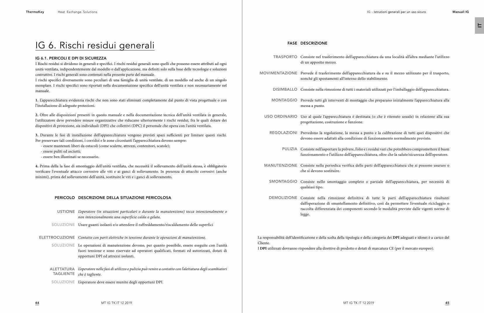
4544
Heat Exchange SolutionsThermoKey IG - Istruzioni generali per un uso sicuro Manuali IG
IT
MT IG TK IT 12 2019MT IG TK IT 12 2019
IG 6. Rischi residui generaliIG 6.1. PERICOLI E DPI DI SICUREZZAI Rischi residui si dividono in generali e specifici. I rischi residui generali sono quelli che possono essere attributi ad ogni unità ventilata, indipendentemente dal modello o dall'applicazione, ma definiti solo sulla base delle tecnologie e soluzioni costruttive. I rischi generali sono contenuti nella presente parte del manuale.I rischi specifici diversamente sono peculiari di una famiglia di unità ventilate, di un modello od anche di un singolo esemplare. I rischi specifici sono riportati nella documentazione specifica dell'unità ventilata e non necessariamente nel manuale.
1. L’apparecchiatura evidenzia rischi che non sono stati eliminati completamente dal punto di vista progettuale o con l’installazione di adeguate protezioni.
2. Oltre alle disposizioni presenti in questo manuale e nella documentazione tecnica dell'unità ventilata in generale, l'utilizzatore deve prevedere misure organizzative che riducano ulteriormente i rischi residui, fra le quali dotare dei dispositivi di protezione, sia individuali (DPI) che collettivi (DPC) il personale che opera con l'unità ventilata.
3. Durante le fasi di installazione dell’apparecchiatura vengono previsti spazi sufficienti per limitare questi rischi. Per preservare tali condizioni, i corridoi e le zone circostanti l’apparecchiatura devono sempre:
- essere mantenuti liberi da ostacoli (come scalette, attrezzi, contenitori, scatole);- essere puliti ed asciutti;- essere ben illuminati se necessario.
4. Prima della la fase di smontaggio dell'unità ventilata, che necessità il sollevamento dell'unità stessa, è obbligatorio verificare l'eventuale attacco corrosivo alle viti e ai ganci di sollevamento. In presenza di attacchi corrosivi (anche minimi), prima del sollevamento dell'unità, sostituire le viti e i ganci di sollevamento.
SOLUZIONE
SOLUZIONE
USTIONE
ELETTROCUZIONE
L’operatore (in situazioni particolari o durante la manutenzione) tocca intenzionalmente o non intenzionalmente una superficie calda o gelata.
Usare guanti isolanti e/o attendere il raffreddamento/riscaldamento delle superfici
Contatto con parti elettriche in tensione durante le operazioni di manutenzione.
Le operazioni di manutenzione devono, per quanto possibile, essere eseguite con l'unità fuori tensione e sono riservate ad operatori qualificati, formati ed autorizzati, dotati di opportuni DPI ed attrezzi isolanti.
L’operatore nelle fasi di utilizzo e pulizia può venire a contatto con l’alettatura degli scambiatori che è tagliente.
L’operatore deve essere munito degli opportuni DPI.SOLUZIONE
ALETTATURA TAGLIENTE
DESCRIZIONE DELLA SITUAZIONE PERICOLOSAPERICOLO
La responsabilità dell’identificazione e della scelta della tipologia e della categoria dei DPI adeguati e idonei è a carico del Cliente. I DPI utilizzati dovranno rispondere alla direttive di prodotto e dotati di marcatura CE (per il mercato europeo).
FASE DESCRIZIONE
TRASPORTO
MOVIMENTAZIONE
DISIMBALLO
MONTAGGIO
USO ORDINARIO
REGOLAZIONI
PULIZIA
MANUTENZIONE
SMONTAGGIO
DEMOLIZIONE
Consiste nel trasferimento dell’apparecchiatura da una località all’altra mediante l’utilizzo di un apposito mezzo.
Prevede il trasferimento dell’apparecchiatura da e su il mezzo utilizzato per il trasporto, nonché gli spostamenti all’interno dello stabilimento.
Consiste nella rimozione di tutti i materiali utilizzati per l’imballaggio dell’apparecchiatura.
Prevede tutti gli interventi di montaggio che preparano inizialmente l’apparecchiatura alla messa a punto.
Uso al quale l’apparecchiatura è destinata (o che è ritenuto usuale) in relazione alla sua progettazione, costruzione e funzione.
Prevedono la regolazione, la messa a punto e la calibrazione di tutti quei dispositivi che devono essere adattati alla condizione di funzionamento normalmente previsto.
Consiste nell’asportare la polvere, l’olio e i residui vari che potrebbero compromettere il buon funzionamento e l’utilizzo dell’apparecchiatura, oltre che la salute/sicurezza dell’operatore.
Consiste nella periodica verifica delle parti dell’apparecchiatura che si possono usurare o che si devono sostituire.
Consiste nello smontaggio completo o parziale dell’apparecchiatura, per necessità di qualsiasi tipo.
Consiste nella rimozione definitiva di tutte le parti dell’apparecchiatura risultanti dall’operazione di smantellamento definitivo, così da permettere l’eventuale riciclaggio o raccolta differenziata dei componenti secondo le modalità previste dalle vigenti norme di legge.
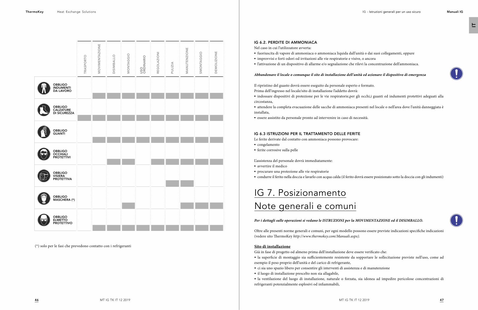
4746
Heat Exchange SolutionsThermoKey IG - Istruzioni generali per un uso sicuro Manuali IG
IT
MT IG TK IT 12 2019MT IG TK IT 12 2019
OBBLIGO INDUMENTI DA LAVORO
OBBLIGO VISIERA PROTETTIVA
OBBLIGO ELMETTO PROTETTIVO
OBBLIGO GUANTI
OBBLIGO CALZATURE DI SICUREZZA
OBBLIGO MASCHERA (*)
OBBLIGO OCCHIALI PROTETTIVI
TR
AS
PO
RT
O
MO
VIM
EN
TAZ
ION
E
DIS
IMB
ALL
O
MO
NTA
GG
IO
RE
GO
LAZ
ION
I
PU
LIZ
IA
MA
NU
TE
NZ
ION
E
SM
ON
TAG
GIO
DE
MO
LIZ
ION
E
US
O
OR
DIN
AR
IO
(*) solo per le fasi che prevedono contatto con i refrigeranti
IG 6.2. PERDITE DI AMMONIACANel caso in cui l’utilizzatore avverta:§ fuoriuscita di vapore di ammoniaca o ammoniaca liquida dall’unità o dai suoi collegamenti, oppure§ improvvisi e forti odori od irritazioni alle vie respiratorie e visive, o ancora§ l’attivazione di un dispositivo di allarme e/o segnalazione che rilevi la concentrazione dell’ammoniaca.
Abbandonare il locale o comunque il sito di installazione dell'unità ed azionare il dispositivo di emergenza
Il ripristino del guasto dovrà essere eseguito da personale esperto e formato.Prima dell’ingresso nel locale/sito di installazione l’addetto dovrà:§ indossare dispositivi di protezione per le vie respiratorie,per gli occhi,i guanti ed indumenti protettivi adeguati alla
circostanza,§ attendere la completa evacuazione delle sacche di ammoniaca presenti nel locale o nell’area dove l’unità danneggiata è
installata,§ essere assistito da personale pronto ad intervenire in caso di necessità.
IG 6.3 ISTRUZIONI PER IL TRATTAMENTO DELLE FERITELe ferite derivate dal contatto con ammoniaca possono provocare:§ congelamento§ ferite corrosive sulla pelle
L’assistenza del personale dovrà immediatamente:§ avvertire il medico§ procurare una protezione alle vie respiratorie§ condurre il ferito nella doccia e lavarlo con acqua calda (il ferito dovrà essere posizionato sotto la doccia con gli indumenti)
IG 7. PosizionamentoNote generali e comuniPer i dettagli sulle operazioni si vedano le ISTRUZIONI per la MOVIMENTAZIONE ed il DISIMBALLO.
Oltre alle presenti norme generali e comuni, per ogni modello possono essere previste indicazioni specifiche indicazioni (vedere sito ThermoKey http://www.thermokey.com/Manuali.aspx).
Sito di installazioneGià in fase di progetto od almeno prima dell'installazione deve essere verificato che:§ la superficie di montaggio sia sufficientemente resistente da sopportare le sollecitazione previste nell’uso, come ad
esempio il peso proprio dell’unità e del carico di refrigerante,§ ci sia uno spazio libero per consentire gli interventi di assistenza e di manutenzione § il luogo di installazione prescelto non sia allagabile,§ la ventilazione del luogo di installazione, naturale o forzata, sia idonea ad impedire pericolose concentrazioni di
refrigeranti potenzialmente esplosivi od infiammabili,
4948
Heat Exchange SolutionsThermoKey IG - Istruzioni generali per un uso sicuro Manuali IG
IT
MT IG TK IT 12 2019MT IG TK IT 12 2019
§ la temperatura locale dell’unità durante le fasi in cui non è operativa, non deve superare i 50°C,§ possano essere impiegati supporti antivibranti e manicotti flessibili sulle tubazioni idrauliche in modo da limitare al
massimo la propagazione delle vibrazioni per via solida,§ l'impatto acustico sia adeguato.
Per le installazioni all’interno inoltre verificare che il locale di installazione deve essere conforme alle prescrizioni della EN 378-3 e alle altre specifiche tecniche e di legge in vigore nel luogo di installazione.
Per le installazioni all’esterno in aggiunta verificare che§ la posizione dell’unità sia ad un livello superiore all’altezza media di neve,§ verificare che la superficie di montaggio sia sufficientemente resistente da sopportare le sollecitazione previste nell’uso
ordinario, come ad esempio il peso proprio dell’unità e del carico di refrigerante e quelle accidentali, come neve, vento e simili facendo riferimento anche alla EN 1991-5.
Predisporre lo spazio e i mezzi necessari all'installazione.
Particolare attenzione deve essere posta nel verificare il pericolo di corrosione galvanica ed in particolare è a carico del progettista/installatore prevedere un sistema di protezione.
Prevedere (a carico dell'installatore/progettista) possibili vibrazioni esterne ad esempio, traffico in prossimità di strade, vibrazioni in prossimità di aeroporti ecc.
Si consiglia l'installazione di ammortizzatori alla base della struttura: fare riferimento al catalogo o al sito internet www.thermokey.com nell’area download catalogo. Per la stima delle sollecitazioni si consiglia di fare riferimento alla EN 1991-6.
L'impiego di sistemi antivibranti può modificare le condizioni di resistenza alle sollecitazioni delle unità ventilate (vento e vibrazioni proprie in particolare).
Per il dimensionamento delle tubazioni, in maniera particolare per quelle contenenti ammoniaca e refrigeranti del gruppo 1, si suggerisce di applicare la EN 1998-6.
Nella scelta del sito di installazione devono essere presi in considerazione una serie di possibili rischi che possono presentarsi sia in fase di installazione che nelle successive fasi di uso ordinario e smontaggio. È in capo al progettista, installatore e/o utilizzatore valutare i rischi presenti nel sito di installazione. Un elenco non esaustivo ma indicativo viene riportato nel seguito.
L'area nei pressi od il suolo al di sotto delle unità ventilate può risultare scivoloso: segnalare debitamente il rischio.
I controventi ed in generale tutte le strutture sporgenti dell' unità ventilata possono presentare un rischio di inciampo.
Per le unità ventilate sospese od appese e per le unità ventilate di grandi dimensioni è possibile che sussista un rischio di urto per la testa in ragione dell'altezza di installazione.
Per le installazioni in quota (su tetti terrazzati, strutture di sostegno o simili mezzi eccedenti i 2m di altezza dal piano di calpestio) sussiste un pericolo di caduta dall'alto che deve essere ridotto per mezzo di DPC.
L'impiego di ammoniaca e refrigeranti del gruppo 1 possono provocare un rischio di esplosione a seguito di una atmosfera esplosiva. In fase di progettazione devono essere prese tutte le precauzioni necessarie ad evitare questo inconveniente.
IG 7.1. SPAZI TECNICI MINIMIGli spazi tecnici minimi possono essere di differente tipo e quindi è necessario rifarsi alle indicazioni specifiche fornite all'interno della documentazione tecnica. Qualora non fossero presenti, richiederle immediatamente a ThermoKey.
IG 7.2. ISPEZIONE ALLA CONSEGNAVerificare la corrispondenza della conferma d'ordine con quella riportata sulla targa identificativa e verificare i parametri elettrici con quelli richiesti. Non procedere all'installazione se c'è difformità dei parametri.
Se l'unità ventilata presenta un difetto al momento del disimballo e/o dell'installazione, segnalarlo immediatamente al fabbricante e non procedere con le fasi successive senza una esplicita autorizzazione.
IG 7.3. DISIMBALLO DELL'UNITÀGli imballaggi possono essere di differente tipo e quindi è necessario rifarsi alle indicazioni specifiche fornite all'interno della documentazione tecnica. Qualora non fossero presenti, richiederle immediatamente a ThermoKey e non procedere con nessuna operazione di disimballo.
IG 7.4 COLLOCAZIONEÈ vietato sostare e transitare nel raggio di azione di qualsiasi macchina di sollevamento.
Ove presente, è obbligatorio togliere il film protettivo dalla carenatura, dopo l’installazione.
Per l'istallazione che prevedono il lavoro in altezza o in esposizione con rischio di caduta, non usare scale, ma seguire le normative nazionali vigenti sulla sicurezza nei "lavori in quota".
I lavori in quota possono essere effettuati soltanto se le condizioni meteorologiche non mettono in pericolo la sicurezza dei lavoratori.
5150
Heat Exchange SolutionsThermoKey IG - Istruzioni generali per un uso sicuro Manuali IG
IT
MT IG TK IT 12 2019MT IG TK IT 12 2019
IG 8. InstallazioneL'installazione è la fase successiva alla collocazione dell'unità ventilata nella quale si eseguono le operazioni di fissaggio della stessa al supporto, si posizionano le controventature, si esegue il rimontaggio delle parti eventualmente smontate per la movimentazione.
L'installazione deve essere eseguita secondo le indicazioni riportate nel manuale e secondo le indicazioni della EN 378-3.
Il fissaggio meccanico dell'unità ventilata è a carico dell'installatore. L'unità ventilata è prevista con fori di fissaggio. Se le dimensioni dei fori fossero insufficiente, non aumentarle senza il consenso di ThermoKey.
I diametri dei fori di fissaggio sono l'esito di calcoli statici da parte del fabbricante; gli elementi di fissaggio devono tenere conto del diametro dei fori.Gli elementi di fissaggio devono essere dotati di ogni mezzo idoneo per impedire che si allentino.
Per potere dimensionare i dispositivi di ancoraggio o fissaggio delle unità ventilate impiegare le norme ETAG di riferimento e fare riferimento ai cataloghi tecnici reperibili nel sito internet www.thermokey.com nell’area download catalogo.
Per migliorare la stabilità al carico del vento dell’unità installate all'esterno è possibile impiegare delle controventature. La scelta ed il dimensionamento delle controventature è a carico dell’installatore.
IG 9. Attacchi frigoriferi ed idriciÈ assolutamente vietato adattare alla linea di adduzione la posizione dei collettori che non devono essere forzati dalla loro posizione originale.
§ Nel predisporre gli attacchi delle tubazioni IN/OUT è obbligatorio verificare l’indicazione del flusso del refrigerante applicata in corrispondenza dei manicotti o delle flange. § Si consiglia l’installazione di valvole di intercettazione a monte per facilitare le operazioni di manutenzione. Qualora
l'istallazione di dette valvole introducesse dei rischi, è sempre a carico dell'installatore prevedere le opportune soluzioni circuitali.§ Per Condensatori e Dry Coolers equipaggiati con sistemi adiabatici, è obbligatorio, qualora si preveda temperatura
ambientale inferiore agli 0°C, procedere allo svuotamento dell’acqua dal sistema di alimentazione per prevenire formazioni di ghiaccio.§ Per i collegamenti frigoriferi e idrici è obbligatorio rispettare i diametri degli attacchi predisposti. Qualsiasi tipo di
modifica deve essere preventivamente concordata con l’Ufficio Customer Support ThermoKey, pena la decadenza di ogni responsabilità relativa a danni a persone, animali o cose, a prestazioni inferiori a quelle dichiarate ed infine delle Condizioni di Garanzia.
IG 9.1. COLLEGAMENTI IDRAULICILe connessioni idrauliche devono essere eseguite in aderenza alle normative nazionali o locali; le tubazioni possono essere realizzate in acciaio, acciaio zincato, o PVC. Le tubazioni devono essere accuratamente dimensionate in funzione della portata nominale del refrigerante, della pressione, delle perdite di carico del circuito idraulico e delle
IG 9.2. MONTAGGIO DELLE TUBAZIONI§ Fissare tutte le tubazioni correttamente evitando danni meccanici seguendo una corretta prassi di montaggio e le
indicazioni reperibili nelle Specifiche Tecniche dell’area download del sito www.thermokey.com§ Durante il montaggio sostenere le tubazioni in modo da non sollecitare in maniera inopportuna i sistemi di fissaggio.§ Se l’installazione avviene in aree in cui è consentito il transito di personale, collocare le tubazioni in modo che non
siano ostacolo al transito ed accertarsi che le tubazioni siano connesse con raccordi non facilmente removibili,§ Utilizzare dispositivi per il fissaggio idonei al peso delle tubazioni,in modo tale che l’intero peso non ricada sulle
connessioni provocando rotture e distaccamenti delle stesse dall’unità.
Nelle unità ventilate che impiegano ammoniaca o fluidi esplosivi od infiammabili una scorretta installazione delle tubazioni comporta un rischio di fuoriuscita del refrigerante.
IG 9.3. SALDATURA§ Per le operazioni di collegamento mediante saldatura, al fine di prevenire le perdite, saldare con precisione ed attenzione;§ evitare il surriscaldamento durante la saldatura (pericolo di ridimensionamento eccessivo);§ usare gas di protezione durante la saldatura (evitare incrostazioni eccessive):§ i lavori di saldatura su componenti in pressione possono causare incendi od esplosioni; § eseguire lavori di saldatura solamente con l’unità scarica e non in pressione;§ assicurarsi che i carichi e le vibrazioni non sollecitino l’unità;§ nel saldare le connessioni è vietato indirizzare la fiamma verso l’unità e/o eventuali apparecchiature elettriche installate.
IG 10. Collegamento elettricoI collegamenti elettrici devono essere realizzati in conformità al presente manuale ed agli schemi elettrici forniti nelle Istruzioni e Dati Tecnici ed alle norme relative agli impianti elettrici vigenti nel Paese dove viene installata l’unità.
È obbligatorio effettuare il collegamento a terra dell’apparecchio.
§ Le operazioni di collegamento elettrico devono essere eseguite da personale qualificato, in possesso dei requisiti tecnici necessari stabiliti dal Paese dove viene installata l’unità. § E obbligatorio verificare che la tensione di linea corrisponda a quella riportata sulla targa identificativa.§ La scelta ed il dimensionamento del cavo di alimentazione dell'unità ventilata è in capo al progettista/installatore.§ Nella posa del cavo di alimentazione si suggerisce l'impiego di canalizzazioni o tubazioni che proteggano meccanica-
mente il cavo. Si sconsiglia assolutamente la posa libera a terra non fissata.§ È obbligatorio utilizzare cavi di alimentazione di tipo e sezione minima conforme alla EN 60204-1 ed eventualmente
alle norme tecniche vigenti nel Paese di istallazione.§ Le potenze e gli assorbimenti per il dimensionamento del cavo elettrico di dorsale sono disponibili nella targa identi-
ficativa e/o sui cataloghi tecnici.§ È obbligatorio dotare l'impianto di alimentazione elettrica di dispositivo di protezione contro le sovracorrenti, come ad
esempio un interruttore magnetotermico, e contro le sovratensioni.
temperature di esercizio. Tutti i collegamenti idraulici devono essere isolati utilizzando materiale a celle chiuse di adeguato spessore.
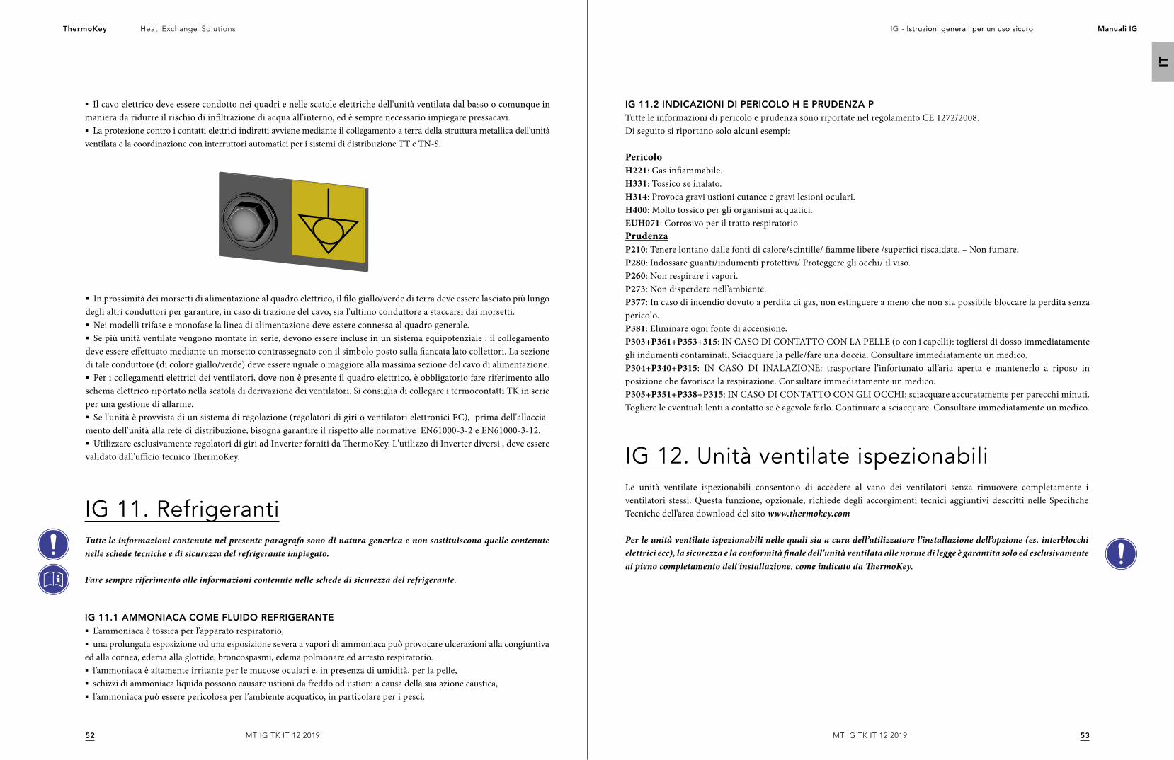
5352
Heat Exchange SolutionsThermoKey IG - Istruzioni generali per un uso sicuro Manuali IG
IT
MT IG TK IT 12 2019MT IG TK IT 12 2019
§ Il cavo elettrico deve essere condotto nei quadri e nelle scatole elettriche dell'unità ventilata dal basso o comunque in maniera da ridurre il rischio di infiltrazione di acqua all'interno, ed è sempre necessario impiegare pressacavi.§ La protezione contro i contatti elettrici indiretti avviene mediante il collegamento a terra della struttura metallica dell'unità
ventilata e la coordinazione con interruttori automatici per i sistemi di distribuzione TT e TN-S.
IG 11. RefrigerantiTutte le informazioni contenute nel presente paragrafo sono di natura generica e non sostituiscono quelle contenute nelle schede tecniche e di sicurezza del refrigerante impiegato.
Fare sempre riferimento alle informazioni contenute nelle schede di sicurezza del refrigerante.
IG 11.1 AMMONIACA COME FLUIDO REFRIGERANTE§ L’ammoniaca è tossica per l’apparato respiratorio,§ una prolungata esposizione od una esposizione severa a vapori di ammoniaca può provocare ulcerazioni alla congiuntiva
ed alla cornea, edema alla glottide, broncospasmi, edema polmonare ed arresto respiratorio.§ l’ammoniaca è altamente irritante per le mucose oculari e, in presenza di umidità, per la pelle,§ schizzi di ammoniaca liquida possono causare ustioni da freddo od ustioni a causa della sua azione caustica,§ l’ammoniaca può essere pericolosa per l’ambiente acquatico, in particolare per i pesci.
IG 12. Unità ventilate ispezionabiliLe unità ventilate ispezionabili consentono di accedere al vano dei ventilatori senza rimuovere completamente i ventilatori stessi. Questa funzione, opzionale, richiede degli accorgimenti tecnici aggiuntivi descritti nelle Specifiche Tecniche dell’area download del sito www.thermokey.com
Per le unità ventilate ispezionabili nelle quali sia a cura dell’utilizzatore l’installazione dell’opzione (es. interblocchi elettrici ecc), la sicurezza e la conformità finale dell'unità ventilata alle norme di legge è garantita solo ed esclusivamente al pieno completamento dell’installazione, come indicato da ThermoKey.
IG 11.2 INDICAZIONI DI PERICOLO H E PRUDENZA PTutte le informazioni di pericolo e prudenza sono riportate nel regolamento CE 1272/2008. Di seguito si riportano solo alcuni esempi:
PericoloH221: Gas infiammabile. H331: Tossico se inalato. H314: Provoca gravi ustioni cutanee e gravi lesioni oculari. H400: Molto tossico per gli organismi acquatici. EUH071: Corrosivo per il tratto respiratorio PrudenzaP210: Tenere lontano dalle fonti di calore/scintille/ fiamme libere /superfici riscaldate. – Non fumare.P280: Indossare guanti/indumenti protettivi/ Proteggere gli occhi/ il viso. P260: Non respirare i vapori. P273: Non disperdere nell’ambiente. P377: In caso di incendio dovuto a perdita di gas, non estinguere a meno che non sia possibile bloccare la perdita senza pericolo.P381: Eliminare ogni fonte di accensione. P303+P361+P353+315: IN CASO DI CONTATTO CON LA PELLE (o con i capelli): togliersi di dosso immediatamente gli indumenti contaminati. Sciacquare la pelle/fare una doccia. Consultare immediatamente un medico. P304+P340+P315: IN CASO DI INALAZIONE: trasportare l’infortunato all’aria aperta e mantenerlo a riposo in posizione che favorisca la respirazione. Consultare immediatamente un medico. P305+P351+P338+P315: IN CASO DI CONTATTO CON GLI OCCHI: sciacquare accuratamente per parecchi minuti. Togliere le eventuali lenti a contatto se è agevole farlo. Continuare a sciacquare. Consultare immediatamente un medico.
§ In prossimità dei morsetti di alimentazione al quadro elettrico, il filo giallo/verde di terra deve essere lasciato più lungo degli altri conduttori per garantire, in caso di trazione del cavo, sia l’ultimo conduttore a staccarsi dai morsetti. § Nei modelli trifase e monofase la linea di alimentazione deve essere connessa al quadro generale.§ Se più unità ventilate vengono montate in serie, devono essere incluse in un sistema equipotenziale : il collegamento
deve essere effettuato mediante un morsetto contrassegnato con il simbolo posto sulla fiancata lato collettori. La sezione di tale conduttore (di colore giallo/verde) deve essere uguale o maggiore alla massima sezione del cavo di alimentazione.§ Per i collegamenti elettrici dei ventilatori, dove non è presente il quadro elettrico, è obbligatorio fare riferimento allo
schema elettrico riportato nella scatola di derivazione dei ventilatori. Si consiglia di collegare i termocontatti TK in serie per una gestione di allarme. § Se l'unità è provvista di un sistema di regolazione (regolatori di giri o ventilatori elettronici EC), prima dell'allaccia-
mento dell'unità alla rete di distribuzione, bisogna garantire il rispetto alle normative EN61000-3-2 e EN61000-3-12.§ Utilizzare esclusivamente regolatori di giri ad Inverter forniti da ThermoKey. L'utilizzo di Inverter diversi , deve essere
validato dall'ufficio tecnico ThermoKey.
Allgemeine Anweisungen für einen Sicheren Gebrauch
ThermoKey S.p.a ist zertifiziert gemäß:
Qualitätsmanagementsystem ISO 9001
Umweltmanagementsystem ISO 14001
Arbeits- und Gesundheitsschutzmanagementsystem OHSAS 18001
MT IG TK DE 12 2019
DIE ORIGINALVERSION DIESER BETRIEBSANLEITUNG IST IN ITALIENISCHER SPRACHE
IG - Allgemeine Anweisungen für einen Sicheren Gebrauch
DE
5655
Heat Exchange SolutionsThermoKey IG - Allgemeine Anweisungen für einen Sicheren Gebrauch Handbuch IG
DE
MT IG TK DE 12 2019MT IG TK DE12 2019
IG - Allgemeine Anweisungen für einen Sicheren Gebrauch
LESEN SIE DIE IN DIESEM HANDBUCH ENTHALTENEN INFORMATIONEN VOLLSTÄNDIG UND AUFMERKSAM DURCH, BEVOR SIE DAS PROJEKT PLANEN UND IN JEDEM FALL VOR JEGLICHER HANDHABUNG, DEM AUSPACKEN, DER MONTAGE, DER AUFSTELLUNG UND INBETRIEBNAHME DES GERÄTES.
Der Hersteller haftet nicht für Personen- und/oder Sachschäden, die auf das Nichtbeachten der Anweisungen in diesem Handbuch zurückzuführen sind.
Das Original dieses Handbuchs in italienischer Sprache finden Sie auf unserer Internetseite www.thermokey.com Die englische Übersetzung entspricht dem Original; Sie finden es auf unserer Internetseite www.thermokey.comÜbersetzungen können Fehler enthalten; im Zweifelsfall ist immer die Originalversion in italienischer Sprache oder die englische Übersetzung heranzuziehen.
Heat Exchange SolutionsThermoKey
PHILOSOPHIE DES HANDBUCHS
Der § 255 des Leitfadens zur Maschinenrichtlinie 2006/42/EG, Revision 2, empfiehlt, die Betriebsanleitung in elektronischer Form und im Internet zur Verfügung zu stellen, um einen Verlust zu vermeiden und die Aktualisierung zu erleichtern.Außerdem schreibt § 275 vor, dass technisch-kaufmännischen Veröffentlichungen wie Kataloge und Betriebsanleitung miteinander übereinstimmen müssen.Viele Geräte aus der Herstellung von ThermoKey sind kunden- oder anlagenspezifisch Auf Grund der oben genannten Punkte und angesichts der Tatsache, dass die Anleitungsleser Planer, Installateure und schließlich auch die Anwender der Anlage sind, folgen die hier aufgeführten technischen Anweisungen der Philosophie aus einer Reihe von Unterlagen zu bestehen, die in ihrer Gesamtheit als HANDBUCH bezeichnet werden.
ALLGEMEINE ANWEISUNGEN FÜR EINEN SICHEREN GEBRAUCH (IG)
ANWEISUNGEN FÜR DIE BEFÖRDERUNG UND DAS AUSPACKEN (IM)
ANWEISUNGEN UND TECHNISCHE DATEN (TC)
SPEZIFISCHE ANWEISUNGEN FÜR BETRIEB UND WARTUNG (IS)
DER AUFBAU DES HANDBUCHS IST IM FOLGENDEN ANGEGEBEN
5857
Heat Exchange SolutionsThermoKey IG - Allgemeine Anweisungen für einen Sicheren Gebrauch Handbuch IG
DE
MT IG TK DE 12 2019MT IG TK DE12 2019
IG 1. EINLEITENDE ANMERKUNGENIG 1.1 ARCHIMEDE SOFTWARE-HINWEISE
IG 2. RECHTLICHE HINWEISEIG 2.1 ORIGINALVERSION
IG 2.2 NUTZUNGSEINSCHRÄNKUNG DIESES HANDBUCHS
IG 2.3 INHALT UND VERSTÄNDNIS DIESES HANDBUCHS
IG 2.4 HAFTUNG
IG 2.5 GESETZLICHE UND TECHNISCHE VORSCHRIFTEN FÜR DIE KONSTRUKTION DER EINHEIT
IG 2.6 BEDEUTUNG DER NORMENREIHE EN378
IG 3. KENNSCHILDER UND ALLGEMEINE ETIKETTEN
IG 4. ALLGEMEINE WARNHINWEISE UND SICHERHEITSVORSCHRIFTENIG 4.1 ALLGEMEINES
IG 4.2 BEFÖRDERUNG, BE- UND ENTLADEN
IG 4.3 TRANSPORT
IG 4.4 LAGERUNG
IG 4.5 ANMERKUNG FÜR DIE LÜFTER
IG 4.6 ELEKTRISCHE SICHERHEIT
IG 4.7 MECHANISCHE SICHERHEIT
IG 5. UNSACHGEMÄSSE UND VERBOTENE BENUTZUNGIG 5.1 SPEZIFISCHE VERBOTE FÜR GERÄTE MIT AMMONIAK
IG 6. ALLGEMEINE RESTGEFAHRENIG 6.1. GEFAHREN UND PSA PERSÖNLICHE SCHUTZAUSRÜSTUNGEN
IG 6.2 AMMONIAK-LECKAGEN
IG 6.3 ANWEISUNGEN FÜR DIE BEHANDLUNG VON VERLETZUNGEN
IG 7. AUFSTELLUNG – ALLGEMEINE HINWEISE FÜR ALLE MODELLEIG 7.1 TECHNISCHER MINDESTPLATZBEDARF
IG 7.2 INSPEKTION BEI LIEFERUNG
IG 7.3 AUSPACKEN DER EINHEIT
IG 7.4 AUFSTELLUNG
IG 8. INSTALLATION
IG 9. KÄLTEMITTEL- UND WASSERANSCHLÜSSEIG 9.1 HYDRAULISCHE ANSCHLÜSSE
IG 9.2 MONTAGE DER LEITUNGEN
IG 9.3 SCHWEISSUNG
IG 10. ELEKTRISCHER ANSCHLUSS
In den Allgemeinen Anweisungen für einen sicheren Gebrauch sind auch die Informationen zur Sicherheit und zum sachgemäßen Gebrauch enthalten, sie umfassen:
ÜBERBLICK
5960
6262
62
62
63
65
65
65
6565
66
66
66
67
61
67
6868
6969
72
72
7274
74
74
74
75
7575
76
76
76
§ In den "Anweisungen für Bewegung und Auspacken" sind mit nummerierten Abbildungen die erforderlichen und zulässigen Arbeitsschritte angegeben, um die verschiedenen Geräte zu bewegen und auszupacken. Bei Spezialgeräten werden die korrekten Informationen im Dokument mit der Nummer der Auftragsbestätigung gekennzeichnet.
Um die Aktualisierung zu erleichtern und Eindeutigkeit der Informationen zu gewährleisten , besteht dieser Teil der Unterlagen zu Geräten aus Katalogen und anderen technischen Dokumenten, die direkt von ThermoKey geliefert werden und/oder auf der Internetseite www.thermokey.com zu finden sind.
§ Im Kapitel AT "Anweisungen und technische Daten" sind die wichtigen technischen Informationen zu jedem einzelnen Gerätetyp aufgeführt, gruppiert nach Familien. Sie umfassen:
- ABMESSUNGEN UND GEWICHTE
- ABMESSUNGEN UND TECHNISCHER MINDESTPLATZBEDARF
- AERAULISCHE UND ELEKTRISCHE DATEN, LEISTUNGSANGABEN
- SCHALLEMISSIONEN
- SCHALTPLÄNE
- TECHNISCHES DATENBLATT
§ Die "spezifischen Gebrauchs- und Wartungsanleitungen" sind spezifisch für jedes Modell und, wenn notwendig, auch für jedes individuelle Gerät mit Motorventilator. Sie umfassen:
IS 1 - BETRIEBSANLEITUNG
IS 2 - BETRIEBSSTÖRUNGEN
IS 3 - WARTUNG
IS 4 - ERSATZTEILE
IG 11. KÄLTEMITTELIG 11.1 AMMONIAK ALS KÄLTEMITTEL
IG 11.2 GEFAHREN- UND SICHERHEITSHINWEISE: H- UND P-SÄTZE
IG 12. INSPEKTIONSMÖGLICHKEIT BEI GERÄTEN MIT LÜFTERN
7778
78
78
6059
Heat Exchange SolutionsThermoKey IG - Allgemeine Anweisungen für einen Sicheren Gebrauch Handbuch IG
DE
MT IG TK DE 12 2019MT IG TK DE12 2019
IG 1. Einleitende Anmerkungen DAS GERÄT DARF NUR FÜR DEN ZWECK VERWENDET WERDEN, FÜR DEN ES KONZIPIERT IST, SIEHE ABSCHNITT „EINLEITENDE ANMERKUNGEN“
1. Die einleitenden Anmerkungen sind ein wesentlicher Bestandteil des Handbuchs und müssen daher sehr aufmerksam gelesen und verstanden werden.
2. Das vorliegende Handbuch ist Teil der technischen Unterlagen des Gerätes. Dieses Handbuch kann durch zusätzliche Angaben ergänzt und zum Teil verändert werden, wenn Personalisierungen oder Betriebsbedingungen, außerhalb der Standardsituation, es erfordern. Generell besteht das Handbuch aus einem Hauptteil und mehreren technischen Anlagen. Sofern es nicht anders angegeben ist, sollte das Handbuch einfach immer als technische Anweisung herangezogen werden, für die korrekte Benutzung des Gerätes.
3. Dieses Handbuch ist über die gesamte Lebensdauer des Gerätes aufzubewahren.
4. Besondere Aufmerksamkeit ist den in diesem Handbuch enthaltenen Betriebsvorschriften zu schenken, da es bei Nichtbeachten derselben zu Schäden an des Gerätes sowie zu Personen-, Tier- bzw. Sachschäden kommen kann.
5. ThermoKey behält sich das Recht vor, dieses Handbuch jederzeit zu ändern; Überarbeitungen in ihrer aktuellsten Form werden immer auf der Webseite www.thermokey.com veröffentlicht. Um festzustellen, ob Ihnen das Handbuch in der letzten Fassung vorliegt, müssen Sie den Revisionsstand überprüfen.
6. Die Herstellerdaten und der Verweis auf die Auftragsnummer des Kunden sind auf dem Typenschild des Gerätes angegeben genauso wie die Auftragsnummer und spezifische Geräteangaben.
Der Verweis auf die Auftragsnummer ist sehr wichtig, weil sie eventuelle kundenspezifische Lösungen und/oder Rahmenvereinbarungen kennzeichnet, die zwischen ThermoKey, als Hersteller, und dem Kunden, als Nutzer, vereinbart wurden.
des Gerätes enthalten.
13. Es ist verboten, Stoffe oder Flüssigkeiten zu verwenden, die die Geräte unsicher machen und ihre Leistungen beeinträchtigen können.
14. Alle technischen Daten der Geräte sowie alle Gebrauchseinschränkungen und Mindestanforderungen, die der Installationsort haben muss, sind in den technischen Katalogen angegeben.
15. Wenn Änderungen oder Variationen an den fertiggestellten Geräten, aber vor der Inbetriebnahme notwendig werden sollten oder wenn die Betriebsbedingungen des Installationsorts nicht den vorgesehenen entsprechen, oder in allen Fällen, in denen ein Unterschied zwischen den Plänen vor der Konstruktion und dem tatsächlichen Zustand des Installationsortes besteht, muss unverzüglich und in jedem Fall vor jedem Änderungseingriff Kontakt zu ThermoKey aufgenommen werden. Andernfalls kann ThermoKey in keiner Weise haftbar gemacht werden.
16. Dem Planer, Installateur bzw. dem Benutzer obliegt die Einhaltung von lokalen Normen und Regelungen in Bezug auf Installation, Betrieb und Entsorgung der Geräte.
17. Unter qualifiziertem Personal versteht sich, sofern es in diesem Handbuch nicht genauer ausgeführt ist, immer eine angemessen ausgebildete und informierte Person oder ein Mitarbeiter, der von einer Person mit einer solchen Ausbildung, Kenntnis und Erfahrung überwacht wird, dass er die Arbeit sachgemäß ausführen sowie Risiken erkennen und daraus folgende Gefahren vermeiden kann.
18. Für die Garantiebedingungen ist Bezug auf die in der Auftragsphase vereinbarten Bedingungen zu nehmen.
19. Die vollständige oder auszugsweise Reproduktion dieses Handbuchs ohne schriftliche Genehmigung des Herstellers ist verboten. Aktualisierte Ausgaben dieses Handbuchs finden Sie auf der Internetseite www.thermokey.com
IG 1.1. ARCHIMEDE SOFTWARE-HINWEISE1. Die Stromspannung bezieht sich auf die Nominaldaten des Herstellers: die Lüfterstromaufnahme kann mit der Lufttemperatur und Spannung variieren.
2. Das Gerät kann für korrosive Atmosphäre ungeeignet sein. Für spezielle Anwendungen kontaktieren Sie bitte ThermoKey. Wenn ein spezielles Lamellenmaterial (Kupfer, beschichtet) ausgewählt wurde bleiben alle andere Materialien Standard. (Für detaillierte Information nehmen Sie bitte das technische Datenblatt des Gerätes zur Hilfe).
3. Abmessungen und Gewicht sind nicht für alle Optionen gültig! Überalles-Abmessungen auf dem Datenblatt sind nur für Geräte ohne Regelung (Für nähere Informationen nehmen Sie das Handbuch des Schaltschrankes zur Hilfe). Bei vertikalen Geräten ist die Standard-Anschlußseite links (auf den Lamellenblock gesehen), rechts auf die Lüfter gesehen.
4. Geräusche vom Kontrollsystem, Sprühsystem etc…sind nicht in der Gerätegeräuscherklärung berücksichtigt. Wahre Werte können aufgrund der Standortbedingungen abweichen.
5. Das Handbuch ist in vier Teile aufgeteilt: IG = Allgemeine Anweisungen , IM = Anweisung zur Behandlung und Auspacken, IT = Anweisungen und technische Daten, IS = Spezifische Anweisung zum Gebrauch und Wartung. Wenn nicht anders im Auftrag angegeben, sind die Anweisungen IT und IS von der Homepage www.thermokey.com herunterzuladen.
6. The unit is equipped with fans that follow the efficiency requirements of ERP directive 2009/125/EC.
7. Nicht originale Ersatzteile müssen im Voraus von ThermoKey genehmigt werden.
8. Die Geräte entsprechen den grundlegenden Gesundheits- und Sicherheitsanforderungen der Maschinenrichtlinie 2006/42/EG, die für alle in Betracht zu ziehenden Standard-Betriebsbedingungen oder den mit dem Kunden vereinbarten Bedingungen gelten.
9. Ausdrücklich verboten ist jeder Gebrauch, der nicht in diesem Handbuch vorgesehen und beschrieben ist bzw. nicht zwischen dem Nutzer und ThermoKey, vor der Fabrikation/Inbetriebnahme der Geräte vereinbart wurde. Der unsachgemäße Gebrauch der Geräte kann zu Gefahrensituationen führen, für deren Folgen ThermoKey keine Haftung übernimmt.
10. Die Geräte sind dafür vorgesehen, dass sie nur mit den Kältemitteln verwendet wird, die im Auftrag angegeben und mit der entsprechenden Nummer auf dem Typenschild angezeigt wird.
11. Es ist verboten, andere Kältemittel als die ausdrücklich angegebenen zu verwenden.
12. Bei der Verwendung von Ammoniak und Kältemitteln der Gruppe 1 können weitere Vorschriften und Gebrauchsanweisungen über die in dieser Anleitung hinaus erforderlich sein, sie sind aber in jedem Fall im Handbuch
6261
Heat Exchange SolutionsThermoKey IG - Allgemeine Anweisungen für einen Sicheren Gebrauch Handbuch IG
DE
MT IG TK DE 12 2019MT IG TK DE12 2019
7. Gemäß EN 13487 wurde der für dieses Gerät deklarierte Schalldruckpegel in Freifeldbedingungen auf einer reflektierenden Ebene mit einer parallelen Oberfläche berechnet. Mit Bezug auf ISO 3744 , wenn der Messunterschied des Gerätes zwischen ON und OFF < = 6 dB(A) ist, erfüllt nicht die in der Norm vorgeschriebene Geräuschmessung. Hintergrundgeräusche kleiner als 30 dB(A) sind typisch für innen und ruhige Umgebungen. Der Schalldruck des Gerätes, wie in ThermoKey-Datenblättern ausgewiesen, betrachtet.diese Hintergrundgeräusche als vernachlässigbar. Die Toleranz des ausgewiesenen Schalls ist +/-2dB(A).
8. S x x x x : Seriennummer aus einer Kombination von Standardoptionen, erhältlich auf Archimede (beschrieben im ZUBEHÖR-Teil) und spezifischen Anfragen. Der Code erscheint auf der Auftragsbestätigung (als Teil des Gerätecodes) und auf dem Typenschild des Gerätes. Hinweis: Für jeden Bereich sind die verfügbaren Optionen im Katalog in der Tabelle und Zubehör aufgelistet. Das Register der Kombinationen von Optionen, die dem Code S x x x x zugeordnet sind, ist auf Anfrage erhältlich.
9. Die Lieferung von Standardgeräten gilt ab Werk. Für besondere Bedingungen (z.B. große Stückzahlen, besondere Spezifikationen ..) wenden Sie sich bitte an die Verkaufsabteilung.
10. Das Standardgerät ist nicht selbstentleerend: Flüssigkeitsaustritt (Wasser / Glykol) hängt eng mit dem Gefrierpunkt und der tatsächlichen Betriebszeit des Geräts zusammen.Wenden Sie sich für selbstentleerende Konstruktionen an ThermoKey für spezielle Angebote."
11. Die in der Auslegung angebene Luftweite entspricht der Entfernung vom Lüfter wenn die Luftgeschwindigkeit 0.25m/s entspricht. Die Luftweite bezieht sich auf die Standard-Luftweite des Lüfters: für Verdampfer und kommerzielle Modelle mit Dreieck oder Einphasenbetrieb, für Doppelblock-Modelle mit serientypischen Anschlüssen.
12. Die Dimensionierung erfolgt durch eine Simulation des Auswahlprogrammes, welche nicht den Einfluss der Installationskonditionen berücksichtigt.
13. Zur Berechnung des max. Betriebsdruckes wird der Druck bzgl. der Kondensationstemperatur berücksichtigt (z.B. Mittelwert)
14. Bei Geräten mit Microchannel-Block müssen unbedingt die Verfahren auf der ThermoKey-Website befolgt werden (Hinweise für die Verwendung von TK-Mikrokernen)
15. Flüssigkeitsgruppe in Übereinstimmung der Richtlinie 2014/68 / EG.
16. Die Daten auf dem Lüfteretikett repräsentieren nicht die schlechtesten Absorptionsbedingungen.
17. Die angegebenen Leistungen sind für HLK-Anwendungen geeignet mit Luftstrom im freien Feld auf Block- und Lüfterseite (Rezirkulation oder jegliche luftströmungsreduzierende Elementen sind zu vermeiden) und mit gleichmäßigen Eintrittstemperaturen in den Block (Bedingungen, unter denen angrenzende Elemente Temperaturschwankungen verursachen könnten, sind zu vermeiden).Für andere kritische Anwendungen (z. B. Industrie, Stromversorgung) wenden Sie sich bitte an ThermoKey.
18. ThermoKey behält sich das Recht vor, die technischen Daten, Zeichnungen und Preise der Archimede-Software jederzeit und ohne vorherige Ankündigung zu ändern. Bitte beachten Sie die Software-Version und EULA der Software in Abschnitt "?".
19. Die Archimede-Software basiert auf den neuesten Bibliotheken von Refprop für Öle, Kältemittel und Mischungen. Datenaktualisierungen können zu einer anderen Leistung der Geräte führen als bei früheren Versionen von Archimede.
20. Achten Sie darauf, dass sich die im technischen Datenblatt angegebenen Gesamtabmessungen und das Gewicht des mit dem EPS-System ausgestatteten Geräts auf das Modell ohne elektrisches Zubehör und montierte Befeuchtungspads beziehen. Die Variation der möglichen Optionskombinationen finden Sie in folgenden Hinweise!Beachten Sie, dass die an der Seite des Modells montierten Befeuchtungspads auf der Breite des Modellabstands insgesamt 440 mm hervorstehen, während sie die Längen- und Höhenabmessungen des Modells nicht beeinträchtigen. Darüber hinaus stehen die an den Modellen montierten seitlichen Verrohrung ca. 320mm mehr zusammen als die Breite der Trockenrückkühlerbaureiche. Berücksichtigen Sie, dass der Schaltschrank und Verbindungs- Wasserzuleitungen abhängig von den ausgewählten und gewünschten Kombination bis zu 400 mm aus den Enden des Modells herausragen.Betrachten Sie 60 kg zusätzliche für jedes Modul (pro Lüftersegment), sowie das Betriebsgewicht mit nassen Befeuchtungsmodulen. Bitte beachten Sie, dass bei nicht optimaler Wartung der Sammelwannen oder der Einspeisung oberhalb der Pads mögliches Restwasser in der Sammelwanne und den einzigen Entleerungsrohren des EPS-Systems verbleibt, dies entspricht ca 30 Kilogramm pro Modul. Berücksichtigen Sie die vormontierten Verbindungsleitungen des EPS-Systems zum Wasserversorgungsnetz am Modell von etwa 25 kg pro Einheit. Berücksichtigen Sie das Gewicht der möglichen vormontierten Schalttafel des EPS-Systems am Modell von etwa 35 kg pro Einheit.
IG 2. Rechtliche AnmerkungenIG 2.1. ORIGINALVERSIONDie Originalversion dieses Handbuchs ist in italienischer Sprache, sie begleitet jede offizielle Übersetzung des Handbuchs. Nicht vom Hersteller genehmigte Übersetzungen des Handbuchs sind als ungültig zu betrachten.
Die Verwendung von nicht genehmigten Kopien bzw. Übersetzungen dieses Handbuchs und/oder die Verwendung von Übersetzungen ohne die italienische Originalversion stellen ThermoKey von jeder Folge und möglichen Haftung bei Unfällen frei.
IG 2.2. ANWENDUNGSGRENZEN DIESES HANDBUCHSDieses Betriebs- und Wartungshandbuch wurde für die Geräte vorbereitet, die für den EU-Markt bestimmt sind und das CE-Symbol tragen.
Dieses Betriebs- und Wartungshandbuch gilt nicht für die Handelseinführung bzw. die Verwendung der Geräten in Ländern, die nicht der Europäischen Union angehören.
IG 2.3. INHALT UND VERSTÄNDNIS DES HANDBUCHSWenn der Planer, Installateur bzw. der Benutzer (nachfolgend als Bediener identifiziert) in diesem Handbuch nicht die technischen Informationen finden, die für die sichere Installation, Betrieb, Wartung bzw. Entsorgung der Einheit erforderlich sind, oder wenn sie Zweifel an den korrekten Verfahren für Installation, Betrieb, Wartung bzw. Entsorgung haben, sind sie aufgefordert, sich mit ThermoKey in Verbindung zu setzen. Dieses Betriebs- und Wartungshandbuch wurde so erstellt, dass es möglichst umfassend und klar für die jeweilige Vorbereitung und Kompetenz der Benutzer sein soll.
6463
Heat Exchange SolutionsThermoKey IG - Allgemeine Anweisungen für einen Sicheren Gebrauch Handbuch IG
DE
MT IG TK DE 12 2019MT IG TK DE12 2019
Das mangelnde Verständnis für den Inhalt dieses Handbuchs oder ein unvollständiges Verständnis seiner Angaben sind eine ausreichende Bedingung, um alle Planungs-, Installations-, Betriebs-, Wartungs- bzw. Entsorgungsarbeiten an diesem Gerät sofort zu unterbrechen.
Wenn die Bediener ihre Tätigkeiten fortsetzen, ohne dass sie dieses Betriebs- und Wartungshandbuch perfekt und vollständig verstanden haben bzw. ohne dass sie über alle erforderlichen Kenntnisse und Angaben für ihre Tätigkeit verfügen, übernimmt ThermoKey keine Haftung für Folgen daraus.
ThermoKey betrachtet die fehlende Meldung von Fehlern, Auslassungen, Widersprüchen etc. in diesem Handbuch in Bezug auf die Anweisungen und technischen Angaben als Fahrlässigkeit: Der Planer, der Installateur und der Benutzer (Wartungstechniker) müssen ThermoKey unverzüglich Situationen melden, die die Sicherheit von Personen, Sachen und Umwelt beeinträchtigen könnten, und dabei mit der erforderlichen Kompetenz, Professionalität, Teamgeist und Sorgfalt vorgehen.
Jedes fahrlässige, nicht umsichtige Verhalten oder ein Verhalten, das auf geringe fachlich-professionelle Kompetenz hinweist, stellt den Hersteller von allen möglichen Folgen und Haftungen frei.
IG 2.4. HAFTUNGHaftung des HerstellersDer Hersteller ist verantwortlich für die Projektentwicklung, Konstruktion, Abnahme und Verpackung der Geräte mit dem Ziel der Vermarktung in der Europäischen Union. Der Hersteller garantiert, dass das Gerät so geplant, konstruiert, abgenommen und verpackt ist, dass die grundlegenden Anforderungen in den einschlägigen EU-Richtlinien beachtet werden und dass die Konformität damit in entsprechender, geeigneter Weise geprüft wurde.Obwohl der Hersteller nicht verantwortlich ist für das Auspacken, die Installation, Inbetriebnahme, Wartung, Ausbau und Entsorgung enthalten diese Anleitungen die größtmögliche Anzahl an nützlichen Informationen für den gesamten Lebenszyklus des Gerätes.Alle Teile dieses Gerätes wurden so entwickelt, gefertigt und getestet, dass sie allen normal absehbaren Belastungen standhalten, die im normal vorhersehbaren Gebrauch eintreten können: Es kann keine Garantie für Sicherheit bzw. Betrieb erteilt werden, wenn die Geräte in Betriebsbedingungen eingesetzt werden, die nicht ausdrücklich von ThermoKey in Betracht gezogen wurden und damit verboten sind.
Installation, Betrieb, Wartung bzw. Entsorgung der Geräte in verbotenen Bedingungen, die nicht vorgesehen waren bzw. abweichend von den von ThermoKey in Betracht gezogen Bedingungen sind stellen den Hersteller von jeglichen möglichen Konsequenzen und Haftungen frei.
Haftung des Planers und des InstallateursGemäß Norm EN 378-4 sind Installateure bzw. Planer verpflichtet die Risiken einzuschätzen und Notfall-Vorrichtungen sowie Alarm-Systeme vorzubereiten. Genauso ist eine verständliche Anweisung für die Kälteanlage oder Kältesystem anzufertigen, in welche das Gerät eingebaut ist. Planer bzw. Installateure haben auch die Aufgabe, Empfehlungen und Richtlinien für die Beförderung und Lagerung des Gerätes außerhalb der Niederlassungen bzw. der Lager des Herstellers zu etablieren. Insbesondere müssen Planer bzw. Installateure die Vorschriften des Herstellers prüfen und deren Einhaltung während des Handlings, Transportes und Lagerung sicherstellen.
Falsche Einschätzung von Risiken oder eine unzureichende Auswahl an Notfall-Vorrichtungen und Alarm-Systemen durch den Planer bzw. den Installateur, enthebt ThermoKey von möglichen Konsequenzen und Haftungen jeder Art.
Der Planer ist verantwortlich für die Auslegung der Kälteanlage oder Kältesystems, in welche das Gerät installiert wird und sind verantwortlich für die Leistung als auch für Sicherheitsfragen. Der Planer hat die Verantwortung, die geeignetsten Komponenten für die Anlage, die er plant, im Rahmen der vom Hersteller vorgegebenen Verwendung zu wählen. Die Planer müssen ausreichend erfahren und kompetent sein, um den Inhalt dieses Betriebs- und Wartungshandbuchs sowie aller anderen technisch-kaufmännischen Dokumente zum Gerät klar zu verstehen; die Kenntnisse müssen ebenso ausreichend sein, um mit dem Hersteller eventuelle Rückfragen abzuklären und somit eine funktionale, sichere und "state-of-the-art" Anlage/System zu implementieren. Im Einzelnen muss der Planer in der Lage sein, die logisch absehbaren Betriebsbedingungen der Anlage zu erkennen (Umwelt, Befestigung, Lasten und Belastungen, Anschluss an Elektro- und Hydraulikanlagen, Flüssigkeitsleitungen usw.) und zu prüfen, ob das Gerät für die gegebenen Bedingungen geeignet ist.
Eine falsche Erkennung der Betriebsbedingungen für das Gerät durch den Planer stellt ThermoKey von jeglichen Konsequenzen und Haftung frei.
Wenn das Projekt in mehrere Teile aufgeteilt wird, wird der Projektkoordinator, wer auch immer es sei, als Projektplaner betrachtet.Der Installateur ist verantwortlich für die Installation und die Umsetzung der Anlage entsprechend den Projektangaben, den Spezifikationen der Komponenten gemäß den Herstellerangaben und der sachgerechten Ausführung. Die Installateure müssen ausreichend erfahren und kompetent sein, um den Inhalt dieses Betriebs- und Wartungshandbuchs sowie aller anderen technisch-kaufmännischen Dokumente zum Gerät klar zu verstehen; die Kenntnisse müssen ebenso ausreichend sein, um mit dem Hersteller eventuelle Rückfragen abzuklären, und somit eine funktionale, sichere und sachgerechte Anlage/System zu implementieren.
Das Personal, das an den verschiedenen Phasen der Geräteinstallation und Inbetriebnahme mitarbeitet, muss kompetent und geschult sein. Sofern zutreffend, muss ein Mindestniveau gemäß den Vorgaben in der Norm EN 13313 garantiert sein.
Wenn die Installation in mehrere Teile aufgeteilt wird, wird der Koordinator des Einbaus, wer auch immer es sei, als Installateur betrachtet.
Haftung des Anlagenführers/KältesystembedienersDer Anlagenbediener ist die Person, die die Anlage betreibt, also ist das Gerät der Handlungsgegenstand dieses Betriebs- und Wartungshandbuches. Der Anlagenbediener ist auch für die Wartung der Einheit verantwortlich.
Das Personal, das an den verschiedenen Phasen der Geräteinstallation und Inbetriebnahme mitarbeitet, muss kompetent und geschult sein. Sofern zutreffend, muss ein Mindestniveau gemäß den Vorgaben in der Norm EN 13313 garantiert sein.
Der Anlagenführer sollte nur mit kompetentem und geschultem Personal zusammen arbeiten, mit der nötigen Schutzausrüstung und qualifiziert für die Kontrolle, Wartung, Reparatur, Not-Aus und Entsorgung des Gerätes.
Es ist zu beachten, dass die Planung der Kälteanlage oder Kältesystems nicht von ThermoKey durchgeführt wird und daher von jeder Konsequenz bzw. Haftung durch falsche Planung bzw. Installation freigestellt wird.
Es wird daran erinnert, dass die Einheiten vom Hersteller technisch verändert bzw. aktualisiert werden können. Es obliegt dem Anlagenführer zu prüfen, ob die Anlage oder System und die neue Version des Einheit Gerätes kompatibel sind.
6665
Heat Exchange SolutionsThermoKey IG - Allgemeine Anweisungen für einen Sicheren Gebrauch Handbuch IG
DE
MT IG TK DE 12 2019MT IG TK DE12 2019
IG 2.5 GESETZLICHE UND TECHNISCHE NORMEN FÜR DEN BAU DER EINHEITFür die vom Hersteller angewandten Herstellungsstandards beziehen Sie sich auf die Erklärung, die ThermoKey mit dem Gerät verschickt.
IG 2.6. BEDEUTUNG DER NORMENSERIE EN 378 Die technischen Normen EN 378 sind eine Reihe von vier Richtlinien (EN 378-1, EN 378-2, EN 378-3 und EN 378-4), die eine wesentliche Leitlinie für die Projektplanung, Installation, Ausführung, Wartung und Entsorgung der Anlagen und der dazugehörigen Kältegeräten darstellen.Die Normen der Serie geben eine vollständige Übersicht über die Sicherheitsaspekte, die von Planern, Installateuren, Anlagenbedienern und Wartungspersonal berücksichtigt werden müssen.Für die Sicherheit der Personen, Eigentum und Umwelt ist die Durchsetzung dieser Normen, welche zur EN 378 Gruppe gehören und die Gerätenutzung als Gegenstand dieses Handbuches behandeln, für ThermoKey von höchster Wichtigkeit. Die fehlende Einhaltung der Normenvorschriften kann im Wesentlichen, aber nicht ausschließlich, zu folgenden Konsequenzen führen:§ Gefahr des Austritts oder Emission des Kältemittels, was zu Brand oder Explosion und zu Personen-, Sach- und
Umweltschäden führen kann,§ Unfallgefahr in den verschiedenen Phasen von Installation, Betrieb, Wartung und Entsorgung durch die daran
beteiligten Personen.
IG 3. Kennschilder und Allgemeine EtikettenDer Benutzer muss garantieren, dass die Etiketten und Kennschilder, die der Hersteller an dem Gerät angebracht hat, in gutem Zustand, lesbar und gut befestigt sind. Wenn sie abgenutzt, unleserlich oder nicht zu entziffern sind, müssen Etiketten und Kennschilder ersetzt werden.
IG 4. Allgemeine Warnhinweise und SicherheitsvorschriftenIG 4.1. ALLGEMEINES1. Die luftgekühlte Einheit ist für einen automatischen, nicht überwachten Einsatz vorgesehen.
2. Der Planer und/oder der Installateur müssen Druckstöße (Wasserhammer-Effekt) vorhersehen.
3. Der Benutzer ist verantwortlich für die Befestigungssysteme der Geräte und muss dabei sicherstellen, dass sie entsprechend den geltenden ETAG-Vorschriften, für die Art der Halterung, ausgelegt sind.
4. Die Betreiber von Geräten mit gefährlichen Kältemitteln müssen die Anweisungen in den Sicherheitsdatenblättern der jeweiligen Substanz genau einhalten.
5. Grundsätzlich muss bei Geräten mit hoch explosiven oder leicht entzündlichen Kältemitteln für ausreichend Belüftung am Installationsort gesorgt werden: Planer, Installateure und/oder der Benutzer müssen das in Betracht ziehen.
6. Die Lüfter sind für den Dauerbetrieb S1 (Dauerbetrieb bei konstanter Last) ausgelegt. Wenn die Lüfter mit einem ON/OFF-Reglersystem verwendet werden, darf die Schaltung keine zu häufigen Umschaltvorgänge vorsehen (siehe technisches Datenblatt des Lüfters).
7. Neben den vorliegenden Vorsichtshinweisen in diesen Kapiteln können für jedes Modell spezifische Anweisungen zur Verfügung gestellt werden (siehe Webseite ThermoKey http://www.thermokey.com/Manuali.aspx).
IG 4.2. BEFÖRDERUNG, BE- UND ENTLADEN1. Die Beförderung und das Handling beim Be- und Entladen müssen von qualifiziertem Personal durchgeführt werden, das über die geeigneten Mittel gemäß Herstelleranweisungen verfügt.
2. Die Zuständigen für die Beförderung der Einheit müssen im Einzelnen:- prüfen, dass das zur Verfügung stehende Hebemittel das Gewicht der Einheit mit einer angemessenen Sicherheitsspanne aushält,- prüfen, dass keine Personen im Aktionsradius des verwendeten Hebemittels beim Abladen und jedenfalls im betreffenden Arbeitsbereich anwesend sind,- prüfen, dass das Gerät mit den entsprechenden Haken nur an den vom Hersteller angegebenen Punkten angeschlagen wird.
Die mangelnde Beachtung von einem oder mehreren der obigen Punkte sowie jegliches in Gefahr bringen des Bedieners, stellen den Hersteller von jeglichen Konsequenzen und Haftungen frei.
Die mangelnde Beachtung der obigen Anweisungen kann Schäden an Personen verursachen wie:- Quetschen- Abscheren von Gliedmaßen
Außerdem kann sie zu Schäden an der Einheit führen und so den korrekten Betrieb beeinträchtigen.
IG 4.3. TRANSPORT Bei See- oder speziell bei Landtransporten mit besonderen Straßenkonditionen (holperig) müssen von den Geräten alle Teile abgebaut werden, die dabei beschädigt werden und damit spätere Defekte und Fehlfunktionen verursachen könnten. In diesen Fällen sind Sonderverpackungen zu verwenden.
Der Aus- und Wiedereinbau darf nur nach Zustimmung von ThermoKey und mit direkten, genauen Anweisungen der Firma durchgeführt werden. Die mangelnde Einhaltung dieser Anweisung stellt ThermoKey von jeder zukünftigen Haftung frei.
IG 4.4. LAGERUNGWenn das Gerät, vor der Installation, einen oder mehrere Monate lang eingelagert werden muss, sollten die folgenden Vorsichtsmaßnahmen getroffen werden:§ das Gerät bis zur Installation in der Originalverpackung lassen oder die Verpackung so wieder herstellen, dass ein entsprechender
Schutzgrad wie bei der Originalverpackung gegen Wettereinflüsse, Staub, Insekten oder Kleinnager garantiert ist,§ an einem überdachten Ort bei Temperaturen zwischen +15°C und +25ºC und einer Luftfeuchtigkeit zwischen 50% und
70% aufstellen,§ prüfen, dass die Einheit nicht Flüssigkeiten oder korrosiven Dämpfen ausgesetzt ist,§ die Einheiten dürfen beim Lagern und beim Transport nicht gestapelt werden, wenn es nicht ausdrücklich vorgesehen ist.
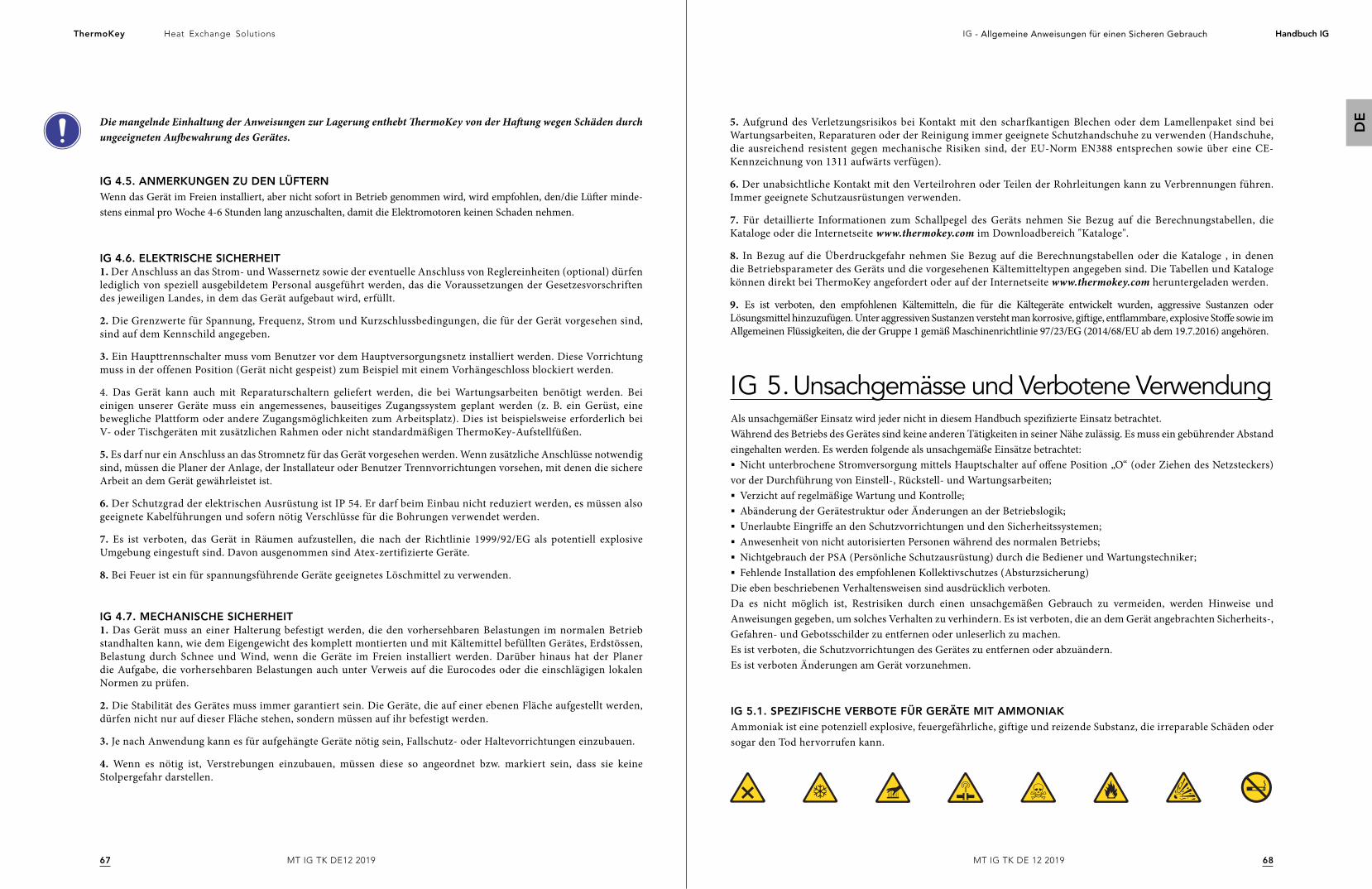
6867
Heat Exchange SolutionsThermoKey IG - Allgemeine Anweisungen für einen Sicheren Gebrauch Handbuch IG
DE
MT IG TK DE 12 2019MT IG TK DE12 2019
Die mangelnde Einhaltung der Anweisungen zur Lagerung enthebt ThermoKey von der Haftung wegen Schäden durch ungeeigneten Aufbewahrung des Gerätes.
IG 4.5. ANMERKUNGEN ZU DEN LÜFTERNWenn das Gerät im Freien installiert, aber nicht sofort in Betrieb genommen wird, wird empfohlen, den/die Lüfter minde-stens einmal pro Woche 4-6 Stunden lang anzuschalten, damit die Elektromotoren keinen Schaden nehmen.
IG 4.6. ELEKTRISCHE SICHERHEIT1. Der Anschluss an das Strom- und Wassernetz sowie der eventuelle Anschluss von Reglereinheiten (optional) dürfen lediglich von speziell ausgebildetem Personal ausgeführt werden, das die Voraussetzungen der Gesetzesvorschriften des jeweiligen Landes, in dem das Gerät aufgebaut wird, erfüllt.
2. Die Grenzwerte für Spannung, Frequenz, Strom und Kurzschlussbedingungen, die für der Gerät vorgesehen sind, sind auf dem Kennschild angegeben.
3. Ein Haupttrennschalter muss vom Benutzer vor dem Hauptversorgungsnetz installiert werden. Diese Vorrichtung muss in der offenen Position (Gerät nicht gespeist) zum Beispiel mit einem Vorhängeschloss blockiert werden.
4. Das Gerät kann auch mit Reparaturschaltern geliefert werden, die bei Wartungsarbeiten benötigt werden. Bei einigen unserer Geräte muss ein angemessenes, bauseitiges Zugangssystem geplant werden (z. B. ein Gerüst, eine bewegliche Plattform oder andere Zugangsmöglichkeiten zum Arbeitsplatz). Dies ist beispielsweise erforderlich bei V- oder Tischgeräten mit zusätzlichen Rahmen oder nicht standardmäßigen ThermoKey-Aufstellfüßen.
5. Es darf nur ein Anschluss an das Stromnetz für das Gerät vorgesehen werden. Wenn zusätzliche Anschlüsse notwendig sind, müssen die Planer der Anlage, der Installateur oder Benutzer Trennvorrichtungen vorsehen, mit denen die sichere Arbeit an dem Gerät gewährleistet ist.
6. Der Schutzgrad der elektrischen Ausrüstung ist IP 54. Er darf beim Einbau nicht reduziert werden, es müssen also geeignete Kabelführungen und sofern nötig Verschlüsse für die Bohrungen verwendet werden.
7. Es ist verboten, das Gerät in Räumen aufzustellen, die nach der Richtlinie 1999/92/EG als potentiell explosive Umgebung eingestuft sind. Davon ausgenommen sind Atex-zertifizierte Geräte.
8. Bei Feuer ist ein für spannungsführende Geräte geeignetes Löschmittel zu verwenden.
IG 4.7. MECHANISCHE SICHERHEIT1. Das Gerät muss an einer Halterung befestigt werden, die den vorhersehbaren Belastungen im normalen Betrieb standhalten kann, wie dem Eigengewicht des komplett montierten und mit Kältemittel befüllten Gerätes, Erdstössen, Belastung durch Schnee und Wind, wenn die Geräte im Freien installiert werden. Darüber hinaus hat der Planer die Aufgabe, die vorhersehbaren Belastungen auch unter Verweis auf die Eurocodes oder die einschlägigen lokalen Normen zu prüfen.
2. Die Stabilität des Gerätes muss immer garantiert sein. Die Geräte, die auf einer ebenen Fläche aufgestellt werden, dürfen nicht nur auf dieser Fläche stehen, sondern müssen auf ihr befestigt werden.
3. Je nach Anwendung kann es für aufgehängte Geräte nötig sein, Fallschutz- oder Haltevorrichtungen einzubauen.
4. Wenn es nötig ist, Verstrebungen einzubauen, müssen diese so angeordnet bzw. markiert sein, dass sie keine Stolpergefahr darstellen.
IG 5. Unsachgemässe und Verbotene VerwendungAls unsachgemäßer Einsatz wird jeder nicht in diesem Handbuch spezifizierte Einsatz betrachtet. Während des Betriebs des Gerätes sind keine anderen Tätigkeiten in seiner Nähe zulässig. Es muss ein gebührender Abstand eingehalten werden. Es werden folgende als unsachgemäße Einsätze betrachtet:§ Nicht unterbrochene Stromversorgung mittels Hauptschalter auf offene Position „O“ (oder Ziehen des Netzsteckers)
vor der Durchführung von Einstell-, Rückstell- und Wartungsarbeiten; § Verzicht auf regelmäßige Wartung und Kontrolle; § Abänderung der Gerätestruktur oder Änderungen an der Betriebslogik; § Unerlaubte Eingriffe an den Schutzvorrichtungen und den Sicherheitssystemen; § Anwesenheit von nicht autorisierten Personen während des normalen Betriebs;§ Nichtgebrauch der PSA (Persönliche Schutzausrüstung) durch die Bediener und Wartungstechniker;§ Fehlende Installation des empfohlenen Kollektivschutzes (Absturzsicherung)
Die eben beschriebenen Verhaltensweisen sind ausdrücklich verboten. Da es nicht möglich ist, Restrisiken durch einen unsachgemäßen Gebrauch zu vermeiden, werden Hinweise und Anweisungen gegeben, um solches Verhalten zu verhindern. Es ist verboten, die an dem Gerät angebrachten Sicherheits-, Gefahren- und Gebotsschilder zu entfernen oder unleserlich zu machen. Es ist verboten, die Schutzvorrichtungen des Gerätes zu entfernen oder abzuändern. Es ist verboten Änderungen am Gerät vorzunehmen.
IG 5.1. SPEZIFISCHE VERBOTE FÜR GERÄTE MIT AMMONIAKAmmoniak ist eine potenziell explosive, feuergefährliche, giftige und reizende Substanz, die irreparable Schäden oder sogar den Tod hervorrufen kann.
5. Aufgrund des Verletzungsrisikos bei Kontakt mit den scharfkantigen Blechen oder dem Lamellenpaket sind bei Wartungsarbeiten, Reparaturen oder der Reinigung immer geeignete Schutzhandschuhe zu verwenden (Handschuhe, die ausreichend resistent gegen mechanische Risiken sind, der EU-Norm EN388 entsprechen sowie über eine CE-Kennzeichnung von 1311 aufwärts verfügen).
6. Der unabsichtliche Kontakt mit den Verteilrohren oder Teilen der Rohrleitungen kann zu Verbrennungen führen. Immer geeignete Schutzausrüstungen verwenden.
7. Für detaillierte Informationen zum Schallpegel des Geräts nehmen Sie Bezug auf die Berechnungstabellen, die Kataloge oder die Internetseite www.thermokey.com im Downloadbereich "Kataloge".
8. In Bezug auf die Überdruckgefahr nehmen Sie Bezug auf die Berechnungstabellen oder die Kataloge , in denen die Betriebsparameter des Geräts und die vorgesehenen Kältemitteltypen angegeben sind. Die Tabellen und Kataloge können direkt bei ThermoKey angefordert oder auf der Internetseite www.thermokey.com heruntergeladen werden.
9. Es ist verboten, den empfohlenen Kältemitteln, die für die Kältegeräte entwickelt wurden, aggressive Sustanzen oder Lösungsmittel hinzuzufügen. Unter aggressiven Sustanzen versteht man korrosive, giftige, entflammbare, explosive Stoffe sowie im Allgemeinen Flüssigkeiten, die der Gruppe 1 gemäß Maschinenrichtlinie 97/23/EG (2014/68/EU ab dem 19.7.2016) angehören.
7069
Heat Exchange SolutionsThermoKey IG - Allgemeine Anweisungen für einen Sicheren Gebrauch Handbuch IG
DE
MT IG TK DE 12 2019MT IG TK DE12 2019
IG 6. Allgemeine Restrisiken
IG 6.1. GEFAHREN UND PSA PERSÖNLICHE SCHUTZAUSRÜSTUNGENMan unterscheidet allgemeine und spezifische Restrisiken. Die allgemeinen Restrisiken sind solche, die jedem Gerät unabhängig von ihrem Modell oder der Anwendung zugeschrieben werden können, da sie von der Technologie und den Konstruktionslösungen abhängen. Diese allgemeinen Restrisiken sind in diesem Abschnitt des Handbuchs enthalten.Die spezifischen Restrisiken dagegen beziehen sich im Besonderen auf eine Familie, ein Modell oder auch ein einzelnes Exemplar eines Gerätes. Die spezifischen Risiken sind in den Unterlagen, spezifisch für das jeweilige Gerät aufgeführt und nicht notwendigerweise im Handbuch enthalten.
1. Von dem Gerät gehen Risiken aus, die bei der Entwicklung oder durch die Installation geeigneter Schutzvorrichtungen nicht vollständig eliminiert werden konnten.
2. Neben den Vorschriften in diesem Handbuch und in den technischen Unterlagen zum Gerät im Allgemeinen muss der Benutzer organisatorische Maßnahmen ergreifen, um die Restgefahren weiter zu verringern. Dazu gehört, dass das Personal, das am Gerät arbeitet, mit der persönlichen Schutzausrüstung (PSA) und mit kollektiven Schutzausrüstungen (KSA) ausgestattet wird.
3. Während der Installation des Geräts wird ein ausreichender Freiraum berücksichtigt, um diese Risiken einzuschränken. Zur Gewährleistung dieses Freiraums müssen die Korridore und die das Gerät umgebenden Bereiche folgendes erfüllen:
- frei sein von Hindernissen (wie Leitern, Werkzeuge, Behälter, Kartons);- sauber und trocken sein;- gut beleuchtet sein, falls notwendig.
4. Bevor ein Gerät zur Demontage angehoben werden kann müssen alle Schrauben und Hebevorrichtungen auf Korrosion überprüft werden. Auch bei minimaler Korrosion sind die Schrauben und Hebevorrichtungen auszutauschen.
LÖSUNG
LÖSUNG
VERBRENNUNGS-GEFAHR
ELETTROCUZIONE
Der Bediener berührt (unter besonderen Umständen oder bei der Wartung) absichtlich oder unabsichtlich eine heiße oder gefrorene Oberfläche:
Falls notwendig, Isolierhandschuhe verwenden und/oder warten, bis sich die Oberfläche abgekühlt/erwärmt hat.
Kontakt mit den unter Spannung stehenden Teilen während Wartungsarbeiten.
Bei den Wartungsarbeiten muss, soweit möglich, das Gerät spannungsfrei sein, und sie dürfen nur von qualifizierten, ausgebildeten und dazu ermächtigen Bedienern ausgeführt werden, die mit geeigneter PSA und Isolierwerkzeug ausgerüstet sind.
Der Bediener muss beim Gebrauch und bei der Reinigung auf die scharfen Lamellenkanten der Wärmetauscher achten.
Der Bediener muss mit der geeigneten PSA ausgestattet sein.LÖSUNG
ALETTATURA TAGLIENTE
BESCHREIBUNG DER GEFÄHRLICHEN SITUATIONGEFAHR
Die Verantwortung für die Identifizierung und die Wahl des Typs und der Kategorie der geeigneten PSA liegt beim Kunden. Die verwendeten PSA müssen den Produktrichtlinien entsprechen und die CE-Kennzeichnung tragen (für den EU-Markt).
PHASE BESCHREIBUNG
TRANSPORT
HANDLING
AUSPACKEN
MONTAGE
NORMALER GEBRAUCH
EINSTELLUNGEN
REINIGUNG
WARTUNG
AUSBAU
VERSCHROTTUNG
Besteht im Transport des Geräts mit einem geeigneten Mittel von einem Ort zu einem anderen Ort.
Besteht im Transfer des Geräts vom und auf das für den Transport verwendete Fahrzeug sowie in der werksinternen Beförderung.
Besteht in dem Entfernen aller zum Verpacken benutzten Materialien.
Besteht in allen Montagearbeiten, die das Gerät auf die Einregulierung vorbereiten.
Gebrauch, für den das Gerät auf der Grundlage der Entwicklung, des Baus und der Betriebsweise bestimmt ist (oder der als üblich angesehen wird).
Bestehen in der Einstellung, der Einregulierung und der Eichung aller Vorrichtungen, die an die normalerweise vorgesehenen Betriebsbedingungen angepasst werden müssen.
Besteht im Entfernen von Staub, Öl und Bearbeitungsrückständen, die den einwandfreien Betrieb und den Gebrauch des Geräts sowie die Gesundheit und Sicherheit des Bedieners beeinträchtigen könnten.
Besteht in der regelmäßigen Kontrolle der Geräteteile, die verschleißen können oder ersetzt werden müssen.
Besteht im kompletten oder teilweisen Zerlegen des Geräts, gleich aus welchen Gründen.
Besteht im endgültigen Entfernen aller aus dem Zerlegen des Geräts hervorgehenden Teile, um eine eventuelle Wiederverwertung oder getrennte Sammlung der Bauteile zu ermöglichen, wie es von den einschlägigen gesetzlichen Normen vorgesehen ist.
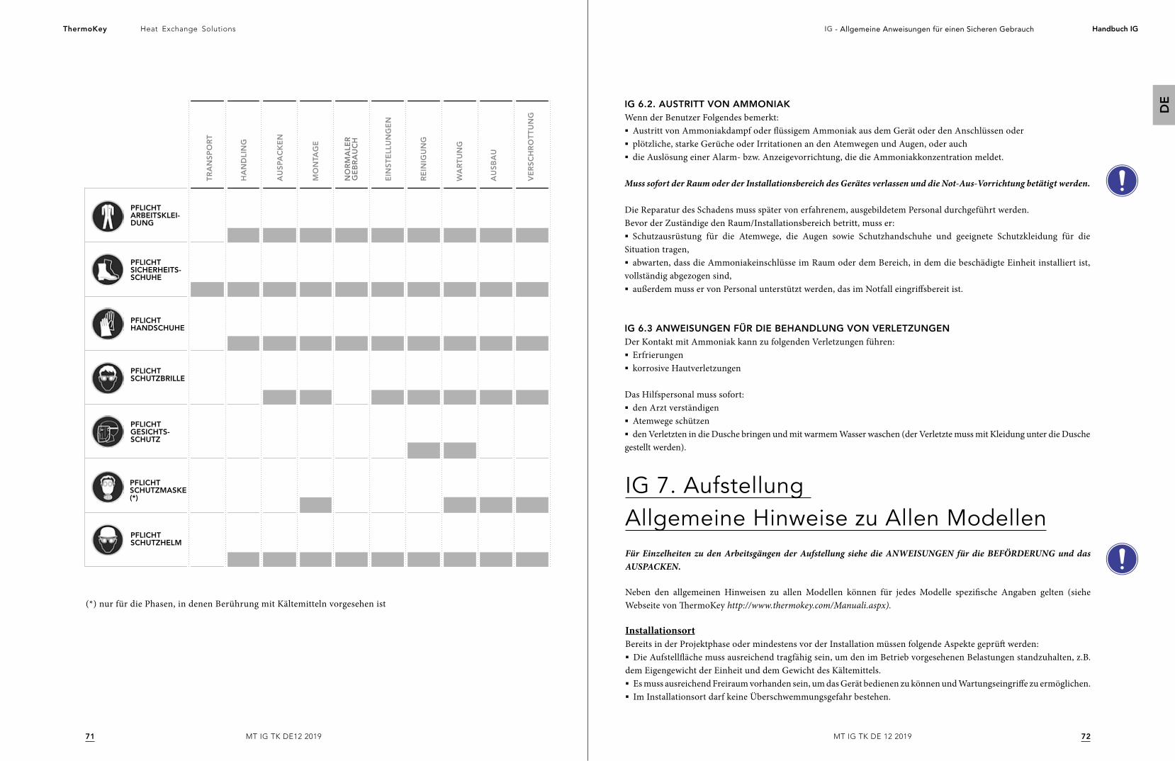
7271
Heat Exchange SolutionsThermoKey IG - Allgemeine Anweisungen für einen Sicheren Gebrauch Handbuch IG
DE
MT IG TK DE 12 2019MT IG TK DE12 2019
PFLICHT ARBEITSKLEI-DUNG
PFLICHT GESICHTS-SCHUTZ
PFLICHT SCHUTZHELM
PFLICHT HANDSCHUHE
PFLICHT SICHERHEITS-SCHUHE
PFLICHT SCHUTZMASKE (*)
PFLICHTSCHUTZBRILLE
TR
AN
SP
OR
T
HA
ND
LIN
G
AU
SPA
CK
EN
MO
NTA
GE
EIN
ST
ELL
UN
GE
N
RE
INIG
UN
G
WA
RT
UN
G
AU
SB
AU
VE
RS
CH
RO
TT
UN
G
NO
RM
ALE
R
GE
BR
AU
CH
(*) nur für die Phasen, in denen Berührung mit Kältemitteln vorgesehen ist
IG 6.2. AUSTRITT VON AMMONIAKWenn der Benutzer Folgendes bemerkt:§ Austritt von Ammoniakdampf oder flüssigem Ammoniak aus dem Gerät oder den Anschlüssen oder§ plötzliche, starke Gerüche oder Irritationen an den Atemwegen und Augen, oder auch§ die Auslösung einer Alarm- bzw. Anzeigevorrichtung, die die Ammoniakkonzentration meldet.
Muss sofort der Raum oder der Installationsbereich des Gerätes verlassen und die Not-Aus-Vorrichtung betätigt werden.
Die Reparatur des Schadens muss später von erfahrenem, ausgebildetem Personal durchgeführt werden.Bevor der Zuständige den Raum/Installationsbereich betritt, muss er:§ Schutzausrüstung für die Atemwege, die Augen sowie Schutzhandschuhe und geeignete Schutzkleidung für die
Situation tragen,§ abwarten, dass die Ammoniakeinschlüsse im Raum oder dem Bereich, in dem die beschädigte Einheit installiert ist,
vollständig abgezogen sind,§ außerdem muss er von Personal unterstützt werden, das im Notfall eingriffsbereit ist.
IG 6.3 ANWEISUNGEN FÜR DIE BEHANDLUNG VON VERLETZUNGENDer Kontakt mit Ammoniak kann zu folgenden Verletzungen führen:§ Erfrierungen§ korrosive Hautverletzungen
Das Hilfspersonal muss sofort:§ den Arzt verständigen§ Atemwege schützen§ den Verletzten in die Dusche bringen und mit warmem Wasser waschen (der Verletzte muss mit Kleidung unter die Dusche
gestellt werden).
IG 7. Aufstellung Allgemeine Hinweise zu Allen ModellenFür Einzelheiten zu den Arbeitsgängen der Aufstellung siehe die ANWEISUNGEN für die BEFÖRDERUNG und das AUSPACKEN.
Neben den allgemeinen Hinweisen zu allen Modellen können für jedes Modelle spezifische Angaben gelten (siehe Webseite von ThermoKey http://www.thermokey.com/Manuali.aspx).
InstallationsortBereits in der Projektphase oder mindestens vor der Installation müssen folgende Aspekte geprüft werden:§ Die Aufstellfläche muss ausreichend tragfähig sein, um den im Betrieb vorgesehenen Belastungen standzuhalten, z.B.
dem Eigengewicht der Einheit und dem Gewicht des Kältemittels.§ Es muss ausreichend Freiraum vorhanden sein, um das Gerät bedienen zu können und Wartungseingriffe zu ermöglichen. § Im Installationsort darf keine Überschwemmungsgefahr bestehen.
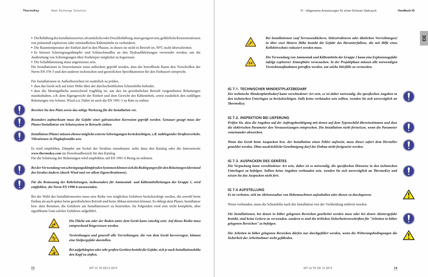
7473
Heat Exchange SolutionsThermoKey IG - Allgemeine Anweisungen für einen Sicheren Gebrauch Handbuch IG
DE
MT IG TK DE 12 2019MT IG TK DE12 2019
§ Die Belüftung des Installationsortes, ob natürliche oder Druckbelüftung, muss geeignet sein, gefährliche Konzentrationen von potenziell explosiven oder entzündlichen Kältemitteln zu verhindern.§ Die Raumtemperatur der Einheit darf in den Phasen, in denen sie nicht in Betrieb ist, 50°C nicht überschreiten.§ Es können Schwingungsdämpfer und Schlauchmuffen an den Hydraulikleitungen verwendet werden, um die
Ausbreitung von Schwingungen über Festkörper möglichst zu begrenzen.§ Die Schalldämmung muss angemessen sein.
Für Installationen in Innenräumen muss außerdem geprüft werden, dass der betreffende Raum den Vorschriften der Norm EN 378-3 und den anderen technischen und gesetzlichen Spezifikationen für den Einbauort entspricht.
Für Installationen in Außenbereichen ist zusätzlich zu prüfen,§ dass das Gerät sich auf einer Höhe über der durchschnittlichen Schneehöhe befindet,§ dass die Montagefläche ausreichend tragfähig ist, um den im gewöhnlichen Betrieb vorgesehenen Belastungen
standzuhalten, z.B. dem Eigengewicht der Einheit und dem Gewicht des Kältemittels, sowie zusätzlich den zufälligen Belastungen wie Schnee, Wind u.ä. Dabei ist auch die EN 1991-5 zu Rate zu ziehen.
Bereiten Sie den Platz sowie das nötige Werkzeug für die Installation vor.
Besonders aufmerksam muss die Gefahr einer galvanischen Korrosion geprüft werden. Genauer gesagt muss der Planer/Installateur ein Schutzsystem in Betracht ziehen.
Installateur/Planer müssen ebenso mögliche externe Schwingungen berücksichtigen, z.B. nahliegender Straßenverkehr, Vibrationen in Flughafennähe usw.
Es wird empfohlen, Dämpfer am Sockel der Struktur einzubauen: siehe dazu den Katalog oder die Internetseite www.thermokey.com im Downloadbereich für den Katalog.Für die Schätzung der Belastungen wird empfohlen, auf EN 1991-6 Bezug zu nehmen.
Bei der Verwendung von schwingungsdämpfenden Systemen können sich die Bedingungen für den Belastungswiderstand des Gerätes ändern (durch Wind und vor allem Eigenvibrationen).
Für die Bemessung der Rohrleitungen, insbesondere für Ammoniak- und Kältemittelleitungen der Gruppe 1, wird empfohlen, die Norm EN 1998-6 anzuwenden.
Bei der Wahl des Installationsortes muss eine Reihe von möglichen Gefahren berücksichtigt werden, die sowohl beim Einbau als auch später beim gewöhnlichen Betrieb und beim Abbau eintreten können. Es obliegt dem Planer, Installateur bzw. dem Benutzer, die Gefahren am Installationsort zu beurteilen. Im Folgenden wird eine nicht komplette, aber signifikante Liste solcher Gefahren aufgeführt.
Die Fläche um oder der Boden unter dem Gerät kann rutschig sein: Auf dieses Risiko muss entsprechend hingewiesen werden.
Verstrebungen und generell alle Vorrichtungen, die von dem Gerät hervorragen, können eine Stolpergefahr darstellen.
Bei aufgehängten oder sehr großen Geräten besteht die Gefahr, sich je nach Installationshöhe den Kopf zu stoßen.
Bei Installationen (auf Terrassendächern, Stützstrukturen oder ähnlichen Vorrichtungen) in über zwei Metern Höhe besteht die Gefahr des Herunterfallens, die mit Hilfe eines Kollektivschutz reduziert werden muss.
Die Verwendung von Ammoniak und Kältemitteln der Gruppe 1 kann eine Explosionsgefahr infolge explosiver Atmosphäre verursachen. In der Projektphase müssen alle notwendigen Vorsichtsmaßnahmen getroffen werden, um solche Störfälle zu vermeiden.
IG 7.1. TECHNISCHER MINDESTPLATZBEDARFDer technische Mindestplatzbedarf kann verschiedener Art sein, es ist daher notwendig, die spezifischen Angaben in den technischen Unterlagen zu berücksichtigen. Falls keine vorhanden sein sollten, wenden Sie sich unverzüglich an ThermoKey.
IG 7.2. INSPEKTION BEI LIEFERUNGPrüfen Sie, dass die Angaben auf der Auftragsbestätigung mit denen auf dem Typenschild übereinstimmen und dass die elektrischen Parameter den Voraussetzungen entsprechen. Die Installation nicht fortsetzen, wenn die Parameter voneinander abweichen.
Wenn das Gerät beim Auspacken bzw. der Installation einen Fehler aufweist, muss dieser sofort dem Hersteller gemeldet werden. Ohne ausdrückliche Genehmigung darf der Einbau nicht fortgesetzt werden.
IG 7.3. AUSPACKEN DES GERÄTESDie Verpackung kann verschiedener Art sein, daher ist es notwendig, die spezifischen Hinweise in den technischen Unterlagen zu befolgen. Sollten keine Angaben vorhanden sein, wenden Sie sich unverzüglich an ThermoKey und setzen Sie das Auspacken nicht fort.
IG 7.4 AUFSTELLUNGEs ist verboten, sich im Aktionsradius von Hebemaschinen aufzuhalten oder diesen zu durchqueren.
Wenn vorhanden, muss die Schutzfolie nach der Installation von der Verkleidung entfernt werden.
Für Installationen, bei denen in höher gelegenen Bereichen gearbeitet werden muss oder bei denen Absturzgefahr besteht, sind keine Leitern zu verwenden, sondern es sind die örtlichen Sicherheitsvorschriften für "Arbeiten in höher gelegenen Bereichen" zu befolgen.
Die Arbeiten in höher gelegenen Bereichen dürfen nur durchgeführt werden, wenn die Witterungsbedingungen die Sicherheit der Arbeitnehmer nicht gefährden.
7675
Heat Exchange SolutionsThermoKey IG - Allgemeine Anweisungen für einen Sicheren Gebrauch Handbuch IG
DE
MT IG TK DE 12 2019MT IG TK DE12 2019
IG 8. InstallationDie Installation ist die Phase nach der Aufstellung des Gerätes: Sie umfasst die Befestigung der Einheit an der Halterung, die Anbringung der Verstrebungen und den Einbau von Teilen, die für die Beförderung eventuell ausgebaut wurden.
Die Installation muss nach den Angaben im Handbuch und nach den Vorgaben der Norm EN 378-3 ausgeführt werden.
Die mechanische Befestigung des Gerätes muss vom Installateur durchgeführt werden. Das Gerät ist mit Befestigungsbohrungen ausgestattet. Wenn die Maße der Bohrungen nicht ausreichen sollten, dürfen sie nicht ohne Genehmigung von ThermoKey erweitert werden.
Die Durchmesser der Befestigungsbohrungen sind das Ergebnis von statischen Berechnungen durch den Hersteller; die Befestigungselemente müssen entsprechend dem Durchmesser der Bohrungen gewählt werden.Die Befestigungselemente müssen mit allen geeigneten Mitteln gesichert werden, um eine Lockerung zu verhindern.
Um die Verankerungs- oder Befestigungsvorrichtungen des Gerätes zu bemessen, sind die entsprechenden ETAG-Normen sowie die technischen Kataloge heranzuziehen, die auf der Internetseite www.thermokey.com im Downloadbereich "Kataloge" zur Verfügung stehen.
Um die Stabilität der im Freien installierten Geräte bei Windbelastung zu verbessern, können Verstrebungen verwendet werden. Die Auswahl und Bemessung der Verstrebungen obliegt dem Installateur.
IG 9. Kältemittel-und WasseranschlüsseEs ist strikt verboten, die Position der Verteiler an die Versorgungsleitung anzupassen, da dieselben nicht aus ihrer ursprünglichen Position verschoben werden dürfen.
§ Bei der Herstellung der Anschlüsse der Leitungen IN/OUT ist der an den Muffen oder dem Flansch angebrachte Kältemittelflusshinweis zu beachten. § Es wird die Installation von Sperrventilen oberhalb des Geräts empfohlen, um die Wartungsarbeiten zu erleichtern. Wenn die
Installation dieser Ventile mit Risiken verbunden ist, hat der Installateur die geeigneten Lösungen für diesen Kälrekreis zu finden.§ Wenn Umgebungstemperaturen unter 0°C abzusehen sind, ist das Wasserzulaufsystem bei Trockenkühler und
Kondensatoren, die mit adiabatischen Systemen ausgestattet sind, zu entleeren, um Vereisungen vorzubeugen.§ Bei den Kältekreis- und Wasseranschlüssen ist der Durchmesser der vorinstallierten Anschlussstücke einzuhalten.
Jeder Änderungseingriff muss zuvor mit der Abteilung Customer Support von ThermoKey vereinbart werden, da andernfalls jegliche Haftung für Personen-, Tier- oder Sachschäden wie auch für eine Leistungsminderung im Vergleich zu den erklärten Werten sowie schließlich die Garantie verfällt.
IG 9.1. HYDRAULIKANSCHLÜSSEDie Hydraulikanschlüsse müssen unter Beachtung der nationalen oder lokalen Vorschriften ausgeführt werden. Die Leitungen müssen aus Stahl, Zinkstahl oder PVC bestehen. Bei der Bemessung der Leitungen müssen sorgfältig folgende Aspekte berücksichtigt werden: Nenndurchfluss des Kältemittels, Druck, Druckverluste des Hydraulikkreises und
IG 9.2. MONTAGE DER ROHRLEITUNGEN§ Alle Rohrleitungen korrekt befestigen und dabei eine sachgemäße Montagetechnik befolgen, um mechanische
Schäden zu vermeiden, sowie die Anweisungen in den Technischen Spezifikationen im Downloadbereich der Webseite www.thermokey.com beachten.§ Beim Befestigen die Rohrleitungen abstützen, so dass die Befestigungssysteme nicht zu stark belastet werden.§ Wenn die Installation in Bereichen erfolgt, in denen Personalverkehr zulässig ist, müssen die Leitungen so angebracht
werden, dass sie den Durchgang nicht behindern. Dabei ist auch sicherzustellen, dass die Verbindungselemente nicht leicht abnehmbar sind.§ Die Befestigungsvorrichtungen müssen für das Gewicht der Rohrleitungen geeignet sein, so dass nicht das gesamte
Gewicht auf den Verbindungen lastet, denn dies kann zu Brüchen und Ablösungen von den Geräten führen.
Bei Geräten, die Ammoniak oder explosive bzw. entzündliche Flüssigkeiten verwenden, besteht bei einer falschen Installation der Rohrleitungen die Gefahr des Austritts von Kältemittel.
IG 9.3. SCHWEISSUNG§ Wenn Verbindungen durch Schweißung hergestellt werden, müssen sie präzise und sorgfältig geschweißt werden, um
Leckagen zu vermeiden.§ Beim Schweißen ist Überhitzung zu vermeiden (Gefahr von zu starkem Schwund).§ Beim Schweißen muss Schutzgas verwendet werden (zu starke Verkrustungen vermeiden).§ Schweißarbeiten an Teilen, die unter Druck stehen, können Brände oder Explosionen verursachen. § Schweißen nur bei entleertem Gerät sowie der Druck muss abgelassen werden.§ Belastungen und Schwingungen dürfen die Einheit nicht belasten.§ Beim Schweißen der Anschlüsse ist es verboten, die Flamme auf das Gerät bzw. eventuell installierte elektrische
Komponenten zu richten.
IG 10. StromanschlussDie elektrischen Anschlüsse müssen in Konformität mit diesem Handbuch und den Schaltplänen, die in den Anweisungen und Technischen Datenblättern enthalten sind, sowie mit den geltenden Vorschriften für Elektroanlagen im Bestimmungsland der Einheit erfolgen.
Das Gerät muß über einem Erdungsanschluss verbunden sein.
§ Die elektrischen Anschlussarbeiten müssen von qualifiziertem Personal durchgeführt werden, das die technischen Voraussetzungen erfüllt, die im Bestimmungsland, in dem das Gerätes installiert wird, vorgeschrieben sind. § Es muss dringend geprüft werden, dass die Leitungsspannung mit der auf dem Typenschild angegebenen Spannung
übereinstimmt.§ Die Auswahl und Bemessung des Versorgungskabels für das Gerät obliegt dem Planer/Installateur.
Betriebstemperatur. Alle Hydraulikanschlüsse müssen mit Dämmmaterial mit geschlossenen Zellen in angemessener Dicke isoliert werden.
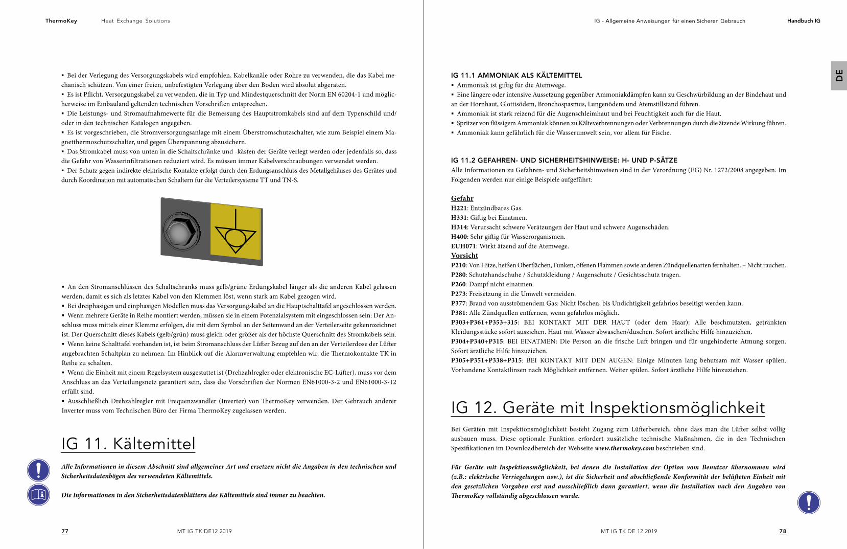
7877
Heat Exchange SolutionsThermoKey IG - Allgemeine Anweisungen für einen Sicheren Gebrauch Handbuch IG
DE
MT IG TK DE 12 2019MT IG TK DE12 2019
§ Bei der Verlegung des Versorgungskabels wird empfohlen, Kabelkanäle oder Rohre zu verwenden, die das Kabel me-chanisch schützen. Von einer freien, unbefestigten Verlegung über den Boden wird absolut abgeraten.§ Es ist Pflicht, Versorgungskabel zu verwenden, die in Typ und Mindestquerschnitt der Norm EN 60204-1 und möglic-
herweise im Einbauland geltenden technischen Vorschriften entsprechen.§ Die Leistungs- und Stromaufnahmewerte für die Bemessung des Hauptstromkabels sind auf dem Typenschild und/
oder in den technischen Katalogen angegeben.§ Es ist vorgeschrieben, die Stromversorgungsanlage mit einem Überstromschutzschalter, wie zum Beispiel einem Ma-
gnetthermoschutzschalter, und gegen Überspannung abzusichern.§ Das Stromkabel muss von unten in die Schaltschränke und -kästen der Geräte verlegt werden oder jedenfalls so, dass
die Gefahr von Wasserinfiltrationen reduziert wird. Es müssen immer Kabelverschraubungen verwendet werden.§ Der Schutz gegen indirekte elektrische Kontakte erfolgt durch den Erdungsanschluss des Metallgehäuses des Gerätes und
durch Koordination mit automatischen Schaltern für die Verteilersysteme TT und TN-S.
IG 11. KältemittelAlle Informationen in diesem Abschnitt sind allgemeiner Art und ersetzen nicht die Angaben in den technischen und Sicherheitsdatenbögen des verwendeten Kältemittels.
Die Informationen in den Sicherheitsdatenblättern des Kältemittels sind immer zu beachten.
IG 12. Geräte mit InspektionsmöglichkeitBei Geräten mit Inspektionsmöglichkeit besteht Zugang zum Lüfterbereich, ohne dass man die Lüfter selbst völlig ausbauen muss. Diese optionale Funktion erfordert zusätzliche technische Maßnahmen, die in den Technischen Spezifikationen im Downloadbereich der Webseite www.thermokey.com beschrieben sind.
Für Geräte mit Inspektionsmöglichkeit, bei denen die Installation der Option vom Benutzer übernommen wird (z.B.: elektrische Verriegelungen usw.), ist die Sicherheit und abschließende Konformität der belüfteten Einheit mit den gesetzlichen Vorgaben erst und ausschließlich dann garantiert, wenn die Installation nach den Angaben von ThermoKey vollständig abgeschlossen wurde.
IG 11.1 AMMONIAK ALS KÄLTEMITTEL§ Ammoniak ist giftig für die Atemwege.§ Eine längere oder intensive Aussetzung gegenüber Ammoniakdämpfen kann zu Geschwürbildung an der Bindehaut und
an der Hornhaut, Glottisödem, Bronchospasmus, Lungenödem und Atemstillstand führen.§ Ammoniak ist stark reizend für die Augenschleimhaut und bei Feuchtigkeit auch für die Haut.§ Spritzer von flüssigem Ammoniak können zu Kälteverbrennungen oder Verbrennungen durch die ätzende Wirkung führen.§ Ammoniak kann gefährlich für die Wasserumwelt sein, vor allem für Fische.
IG 11.2 GEFAHREN- UND SICHERHEITSHINWEISE: H- UND P-SÄTZEAlle Informationen zu Gefahren- und Sicherheitshinweisen sind in der Verordnung (EG) Nr. 1272/2008 angegeben. Im Folgenden werden nur einige Beispiele aufgeführt:
GefahrH221: Entzündbares Gas. H331: Giftig bei Einatmen. H314: Verursacht schwere Verätzungen der Haut und schwere Augenschäden.H400: Sehr giftig für Wasserorganismen. EUH071: Wirkt ätzend auf die Atemwege. VorsichtP210: Von Hitze, heißen Oberflächen, Funken, offenen Flammen sowie anderen Zündquellenarten fernhalten. – Nicht rauchen.P280: Schutzhandschuhe / Schutzkleidung / Augenschutz / Gesichtsschutz tragen. P260: Dampf nicht einatmen. P273: Freisetzung in die Umwelt vermeiden.P377: Brand von ausströmendem Gas: Nicht löschen, bis Undichtigkeit gefahrlos beseitigt werden kann.P381: Alle Zündquellen entfernen, wenn gefahrlos möglich. P303+P361+P353+315: BEI KONTAKT MIT DER HAUT (oder dem Haar): Alle beschmutzten, getränkten Kleidungsstücke sofort ausziehen. Haut mit Wasser abwaschen/duschen. Sofort ärztliche Hilfe hinzuziehen.P304+P340+P315: BEI EINATMEN: Die Person an die frische Luft bringen und für ungehinderte Atmung sorgen. Sofort ärztliche Hilfe hinzuziehen.P305+P351+P338+P315: BEI KONTAKT MIT DEN AUGEN: Einige Minuten lang behutsam mit Wasser spülen. Vorhandene Kontaktlinsen nach Möglichkeit entfernen. Weiter spülen. Sofort ärztliche Hilfe hinzuziehen.
§ An den Stromanschlüssen des Schaltschranks muss gelb/grüne Erdungskabel länger als die anderen Kabel gelassen werden, damit es sich als letztes Kabel von den Klemmen löst, wenn stark am Kabel gezogen wird.§ Bei dreiphasigen und einphasigen Modellen muss das Versorgungskabel an die Hauptschalttafel angeschlossen werden.§ Wenn mehrere Geräte in Reihe montiert werden, müssen sie in einem Potenzialsystem mit eingeschlossen sein: Der An-
schluss muss mittels einer Klemme erfolgen, die mit dem Symbol an der Seitenwand an der Verteilerseite gekennzeichnet ist. Der Querschnitt dieses Kabels (gelb/grün) muss gleich oder größer als der höchste Querschnitt des Stromkabels sein.§ Wenn keine Schalttafel vorhanden ist, ist beim Stromanschluss der Lüfter Bezug auf den an der Verteilerdose der Lüfter
angebrachten Schaltplan zu nehmen. Im Hinblick auf die Alarmverwaltung empfehlen wir, die Thermokontakte TK in Reihe zu schalten.§ Wenn die Einheit mit einem Regelsystem ausgestattet ist (Drehzahlregler oder elektronische EC-Lüfter), muss vor dem
Anschluss an das Verteilungsnetz garantiert sein, dass die Vorschriften der Normen EN61000-3-2 und EN61000-3-12 erfüllt sind.§ Ausschließlich Drehzahlregler mit Frequenzwandler (Inverter) von ThermoKey verwenden. Der Gebrauch anderer
Inverter muss vom Technischen Büro der Firma ThermoKey zugelassen werden.
Instrucciones generalespara un uso seguro
Sistema de Gestión de Calidad ISO 9001
Sistema de Gestión Medioambiente ISO 14001
Sistema de Gestión de Salud y Seguridad
en el lugar de trabajo BS OHSAS 18001
LA VERSIÓN ORIGINAL DE ESTAS INSTRUCCIONESSE REDACTÓ EN ITALIANO
MT IG TK ES 12 2019E
S
8180
Heat Exchange SolutionsThermoKey IG - Instrucciones generales para un uso seguro Manuali IG
ES
MT IG TK ES 12 2019MT IG TK ES 12 2019
LEA CUIDADOSAMENTE Y COMPRENDA TOTALMENTE TODA LA INFORMACIÓN DE ESTAS INSTRUCCIONES ANTES DE REALIZAR EL DISEÑO Y, EN TODO CASO, ANTES DE EFECTUAR CUALQUIER OPERACIÓN DE DESPLAZAMIENTO, DESEMBALAJE, MONTAJE, EMPLAZAMIENTO Y PUESTA EN FUNCIONAMIENTO DEL EQUIPO.
El fabricante no se hará responsable por daños personales o materiales que deriven de la inobservancia de las indicaciones descritas en este documento.
La versión original de este manual ha sido redactada en italiano y está disponible en la página web www.thermokey.com.La traducción al inglés es conforme con el documento original y está disponible en la página web www.thermokey.com.Las traducciones pueden contener errores. En caso de dudas, consulte siempre la versión original en italiano o su traducción al inglés.
Heat Exchange SolutionsThermoKey
LA FILOSOFÍA DEL MANUAL
El comentario n.º 255 de las directrices de aplicación de la revisión 2 de la Directiva de Máquinas 2006/42/CE sugiere poner à disposicón en la Internet un formato electrónico de las instrucciones para evitar perderlas y para facilitar su actualización.Además, el comentario 275 impone que haya correspondencia entre las publicaciones técnico-comerciales, como los catálogos, y el manual.Muchas de las unidades ventiladas fabricadas por ThermoKey se personalizan para un cliente o una planta particular.Con base en los puntos arriba indicados, y tomando en cuenta que las instrucciones están destinadas a los diseñadores de las plantas, los instaladores y los usuarios, la documentación técnica para diseñar y usar correctamente la unidad ventilada está compuesta por varios documentos que, en conjunto, se definen como MANUAL.
INSTRUCCIONES GENERALES PARA UN USO SEGURO (IG)
INSTRUCCIONES DE DESPLAZAMIENTO Y DESEMBALAJE (IM)
INSTRUCCIONES Y DATOS TÉCNICOS (TC)
INSTRUCCIONES ESPECÍFICAS DE USO Y MANTENIMIENTO (IS)
CONTENIDO DEL MANUAL

8382
Heat Exchange SolutionsThermoKey IG - Instrucciones generales para un uso seguro Manuali IG
ES
MT IG TK ES 12 2019MT IG TK ES 12 2019
IG 1. NOTAS PRELIMINARESIG 1.1 NOTAS DE SOFTWARE ARCHIMEDE
IG 2. NOTAS LEGALESIG 2.1 VERSIÓN ORIGINAL
IG 2.2 LÍMITES DE USO DE ESTE MANUAL
IG 2.3 CONTENIDO Y COMPRENSIÓN DEL MANUAL
IG 2.4 RESPONSABILIDADES
IG 2.5 NORMAS LEGALES Y TÉCNICAS ADOPTADAS EN LA CONSTRUCCIÓN DE LA UNIDAD
IG 2.6 IMPORTANCIA DE LA SERIE DE NORMAS EN 378
IG 3. PLACAS Y ETIQUETAS GENÉRICAS
IG 4. ADVERTENCIAS GENERALES Y NORMAS DE SEGURIDADIG 4.1 INFORMACIÓN GENERAL
IG 4.2 DESPLAZAMIENTO, CARGA Y DESCARGA
IG 4.3 TRANSPORTE
IG 4.4 ALMACENAMIENTO
IG 4.5 ANOTACIÓN PARA LOS VENTILADORES
IG 4.6 SEGURIDAD ELÉCTRICA
IG 4.7 SEGURIDAD MECÁNICA
IG 5. USOS INCORRECTOS Y PROHIBIDOSIG 5.1 PROHIBICIONES ESPECÍFICAS PARA LAS UNIDADES VENTILADAS CON AMONIACO
IG 6. RIESGOS RESIDUALES GENERALESIG 6.1 PELIGROS Y EPI DE SEGURIDAD
IG 6.2 PÉRDIDAS DE AMONIACO
IG 6.3 INSTRUCCIONES PARA EL TRATAMIENTO DE LAS HERIDAS
IG 7. EMPLAZAMIENTO: NOTAS GENERALES O COMUNESIG 7.1 ESPACIOS TÉCNICOS MÍNIMOS
IG 7.2 INSPECCIÓN EN EL MOMENTO DE LA ENTREGA
IG 7.3 DESEMBALAJE DE LA UNIDAD
IG 7.4 COLOCACIÓN
IG 8. INSTALACIÓN
IG 9. CONEXIONES FRIGORÍFICAS E HIDRÁULICASIG 9.1 CONEXIONES HIDRÁULICAS
IG 9.2 MONTAJE DE LAS TUBERÍAS
IG 9.3 SOLDADURA
IG 10. CONEXIÓN ELÉCTRICA
En el documento Instrucciones generales para un uso seguro se indica la información sobre la seguridad y el uso correcto, que incluye lo siguiente:
ÍNDICE
8185
8686
86
86
88
90
90
90
9090
83
91
91
92
92
92
9393
9494
97
97
9799
99
99
99
100
100100
101
101
101
§ En el documento “Instrucciones de desplazamiento y embalaje” se indican, por medio de figuras numeradas, las operaciones necesarias y admitidas para el desplazamiento y desembalaje de las distintas unidades ventiladas. En el caso de unidades ventiladas especiales, la información correcta se identificará en el documento por medio del número de confirmación del pedido.
Para facilitar la actualización y la falta de ambigüedad de la información, esta parte de la documentación de la unidad consta de catálogos y otros documentos técnicos directamente provistos por ThermoKey y/o disponibles en la página web www.thermokey.com.
§ En el capítulo TC “Instrucciones y datos técnicos” se indican los datos técnicos para cada tipo de unidad ventilada, agrupados en familias, que incluyen lo siguiente:
- DIMENSIONES Y PESOS
- DIMENSIONES MÁXIMAS Y ESPACIOS TÉCNICOS MÍNIMOS
- DATOS ELÉCTRICOS, DE RENDIMIENTO Y DE FLUJO DE AIRE
- NIVEL DE EMISIONES ACÚSTICAS
- ESQUEMAS ELÉCTRICOS
- BOLETÍN TÉCNICO
§ El documento “Instrucciones específicas de uso y mantenimiento”, que se refiere específicamente a un modelo y, en su caso, a una unidad ventilada en particular, incluye lo siguiente:
IS 1 - INSTRUCCIONES PARA EL FUNCIONAMIENTO
IS 2 - PROBLEMAS DE FUNCIONAMIENTO
IS 3 - MANTENIMIENTO
IS 4 - PIEZAS DE REPUESTO
IG 11. REFRIGERANTESIG 11.1 AMONIACO COMO LÍQUIDO REFRIGERANTE
IG 11.2 INDICACIONES DE PELIGRO (H) Y PRUDENCIA (P)
IG 12. UNIDADES VENTILADAS INSPECCIONABLES
102102
103
103

8584
Heat Exchange SolutionsThermoKey IG - Instrucciones generales para un uso seguro Manuali IG
ES
MT IG TK ES 12 2019MT IG TK ES 12 2019
IG 1. Notas preliminaresLA UNIDAD DEBE USARSE EXCLUSIVAMENTE PARA LOS FINES EXPRESAMENTE PREVISTOS Y DESCRITOS EN EL PÁRRAFO “NOTAS PRELIMINARES”.
1. Las notas preliminares son parte esencial del manual, por lo cual deben ser leídas con atención y comprendidas.
2. Este manual es una parte de la documentación técnica de la unidad ventilada. Este manual se puede integrar con otras indicaciones y puede ser parcialmente modificado en función de personalizaciones o condiciones operativas fuera de norma. En general, el manual consta de una parte principal y varios anejos técnicos. A menos que se especifique lo contrario, en adelante se utilizará el término “manual” para hacer referencia a toda la documentación técnica necesaria para el uso correcto de la unidad ventilada.
3. Conserve este manual durante toda la vida útil de la unidad ventilada.
4. Preste suma atención a las normas de uso descritas en el manual, ya que su inobservancia podría causar daños tanto a la unidad ventilada como a personas, animales y cosas.
5. ThermoKey se reserva el derecho de modificar este manual en cualquier momento; las últimas revisiones siempre se publicarán en la página web www.thermokey.com. Para verificar si usted dispone de la última versión, consulte el índice de revisión.
6. Los datos del fabricante y la referencia al número de pedido del cliente se indican en la placa de identificación de la unidad ventilada que, además de los datos de la unidad, indica también el número de pedido.
7. Las piezas de repuesto que no sean originales deben ser previamente aprobadas por ThermoKey.
8. La unidad ventilada cumple con los requisitos esenciales de salud y seguridad de la Directiva 2006/42/CE, aplicables conforme a lo previsto en las condiciones de uso estándar o acordadas con el cliente.
9. Quedan expresamente prohibidos todos los usos no previstos ni descritos en este manual o que no hayan sido acordados entre el usuario y ThermoKey antes de la fabricación y puesta en servicio de la unidad ventilada. Los usos inapropiados de la unidad ventilada pueden provocar condiciones peligrosas de cuyas consecuencias ThermoKey no se hará responsable.
10. La unidad ventilada está diseñada para utilizarse únicamente con los refrigerantes indicados en el pedido cuyo número que aparece en la placa de identificación.
11. Está prohibido usar líquidos refrigerantes distintos de los que se indican.
12. Para usar amoniaco o refrigerantes del grupo 1, se podrían requerir prescripciones e indicaciones de uso adicionales con respecto a las que se indican en estas instrucciones, las cuales, en todo caso, estarán incluidas en el manual de la unidad ventilada.
La referencia al número de pedido es muy importante porque identifica toda personalización y limitación de uso acordada entre ThermoKey, como fabricante, y el cliente, como usuario.
13. Está prohibido usar sustancias o líquidos que puedan deteriorar el equipo, afectar su seguridad o disminuir el rendimiento de la unidad ventilada.
14. En los catálogos técnicos se indican todos los datos técnicos de las unidades ventiladas, así como todos los límites de uso y las características mínimas que debe tener el lugar de instalación.
15. Si fuera necesario aportar modificaciones o variaciones a la unidad ventilada después de su fabricación, pero antes de su puesta en servicio, o bien si las condiciones operativas del lugar de instalación no fueran las previstas o hubiera diferencias entre lo previsto antes de la fabricación y el estado real del lugar de instalación, habrá que contactar inmediatamente y obligatoriamente a ThermoKey antes de realizar cualquier cambio. De no ser así, ThermoKey no asumirá ninguna responsabilidad.
16. El diseñador, el instalador y/o el usuario tienen la obligación de observar las normas y los reglamentos locales en materia de instalación, uso y eliminación de la unidad ventilada.
17. Salvo en caso de especificaciones adicionales en este manual, por personal capacitado siempre debe entenderse una persona adecuadamente informada, o bien supervisada por otra persona cuya formación, conocimientos y experiencia le permitan realizar los trabajos a la perfección, así como percibir sus riesgos y evitar los peligros asociados.
18. Para conocer las condiciones de garantía, consulte los acuerdos establecidos al hacerse el pedido.
19. Se prohíbe la reproducción total o parcial de este manual sin la autorización escrita del fabricante. Las copias actualizadas de este manual están disponibles en la página web www.thermokey.com.
IG 1.1. NOTAS DE SOFTWARE ARCHIMEDE1. La tensión se refiere a los datos nominales del proveedor: el consumo de los ventiladores puede variar con la temperatura del aire y el sistema de tensión.
2. La unidad podría no ser la adecuada para ambientes muy corrosivos. Para aplicaciones especiales, comuníquese con ThermoKey. Al seleccionar materiales especiales para las aletas (cobre, pintado), todos los demás materiales de la unidad siguen siendo estándar (para más detalles, consulte la descripción técnica del equipo).
3. Las dimensiones y los pesos no son válidos para todas las opciones posibles. Las dimensiones generales en la ficha técnica son para unidades sin controles / paneles eléctricos (para obtener información más detallada, consulte el Manual del panel eléctrico). En caso de unidades de flujo de aire horizontal, la posición estándar de conexiones está a la izquierda según se mira el paquete aleteado.
4. El ruido causado por los sistemas de control, el sistema adiabático, etc., no se considera en la declaración del nivel de ruido del ventilador. Los valores reales también pueden sufrir desviaciones debido a condiciones de la instalación.
5. El manual consta de 4 partes IG = Instrucciones generales, IM = Instrucciones de manejo y desempaque, TC = Instrucciones y datos técnicos, IS = Instrucciones específicas de uso y mantenimiento. Si no se solicita expresamente al momento de realizar el pedido, el usuario debe descargar las instrucciones de TC y de IS de www.thermokey.com ya que no se enviaran en formato de papel.El instalador debe seguir las instrucciones de los manuales arriba indicados y de todos los manuales de los principales componentes eléctricos (por ejemplo, ventiladores, bombas, reguladores…).
8786
Heat Exchange SolutionsThermoKey IG - Instrucciones generales para un uso seguro Manuali IG
ES
MT IG TK ES 12 2019MT IG TK ES 12 2019
IG 2. Notas legalesIG 2.1. VERSIÓN ORIGINALLa versión original de este manual ha sido redactada en italiano y acompaña a cualquier traducción oficial del manual. Las traducciones del manual no autorizadas por el fabricante no se consideran válidas.
El uso de copias o traducciones no autorizadas de este manual y el uso de traducciones que no estén acompañadas del original en italiano eximen a ThermoKey de cualquier responsabilidad por las consecuencias de posibles accidentes.
IG 2.2. LÍMITES DE USO DE ESTE MANUALEste manual de uso y mantenimiento ha sido preparado para las unidades ventiladas destinadas al mercado de la Comunidad Europea que llevan el marcado CE.
Este manual de uso y mantenimiento no abarca la comercialización o el uso de las unidades en países que no sean miembros de la Unión Europea.
IG 2.3. CONTENIDO Y COMPRENSIÓN DEL MANUALSi el diseñador, el instalador o el usuario (en términos generales y omnicomprensivos, los operadores) no hallaran en este manual la información técnica necesaria para la instalación, el uso, el mantenimiento y la eliminación segura de la unidad, o bien si tuvieran dudas con respecto a los métodos correctos de instalación, uso, mantenimiento y eliminación, estos deberán comunicarse con ThermoKey. Este manual de uso y mantenimiento ha sido redactado para ser lo más completo y claro posible en relación con la preparación y las competencias de sus usuarios.La incomprensión total o parcial del contenido de este manual es motivo suficiente para interrumpir inmediatamente cualquier fase de diseño, instalación, uso, mantenimiento y/o eliminación de la unidad misma.
6. La unidad está equipada con ventiladores que cumplen con los requisitos de eficiencia de la directiva ERP 2009/125 / EC
7. De acuerdo con la norma EN 13487, el nivel de presión acústica declarado para esta unidad se ha calculado en condiciones de un volumen sin restricciones sobre un plano reflectante con superficie de referencia paralelepipédica. Con referencia a la norma ISO 3744, cuando la diferencia en la medición entre activado y desactivado es <= 6dB (A), la medición del sonido no alcanza la precisión según requerido por la norma. Los valores de ruido de fondo por debajo de 30dB (A) son típicos de ambientes interiores y tranquilos. La declaración de la presión acústica de la máquina, que figura en las hojas de datos de ThermoKey, considera que el ruido de fondo es despreciable.
8. S x x x x: código de serie que identifica la combinación de opciones estándar seleccionables en Arquímedes (enumeradas y descritas en la sección ACCESORIOS) y especial su petición. El código se muestra en la confirmación del pedido (como parte integral del código de descripción del modelo) y está presente en la etiqueta de datos técnicos del producto. Nota: Para cada gama de producto, las opciones disponibles se enumeran en el catálogo en la Tabla de opciones y accesorios. El registro de las combinaciones de las opciones asociadas con el código S x x x x se puede consultar a petición.
9. La entrega de unidades estándar se considera ex works. Para obtener términos o condiciones especiales (p. Ej., Grandes cantidades, especificaciones especiales), póngase en contacto con el departamento de ventas
10. La unidad estándar no es autodrenante: la elección del fluido (agua / glicol) está estrechamente relacionada con el punto de congelación de la misma y con el período de funcionamiento actual de la unidad.
Para construcción con sistema autodrenante, comuníquese con ThermoKey para obtener ofertas dedicadas.
11. La flecha de aire indicada en las hojas de datos representa la distancia desde el ventilador donde la velocidad del aire corresponde a 0.25 m / s. La flecha de aire se refiere solo al caudal de aire estándar del ventilador: para modelos “cubic”, “light cubic” y comerciales con operación en delta o monofásica, para modelos de doble flujo con conexión según la serie.
12. El dimensionamiento se realiza mediante una simulación del programa de selección que no tiene en cuenta la influencia de las condiciones de instalación.
13. Al seleccionar la presión máxima de operación, se considera el punto medio de la presión asociada con la temperatura de condensación
14. Para unidades de ventiladores con baterías de microcanal, es esencial seguir los procedimientos en el sitio web de ThermoKey “(Indications for the use of TK micro cores)”
15. Grupo de fluidos relacionado con la Directiva 2014/68 / CE.
16. Los datos indicados en la placa de los ventiladores no representan las peores condiciones de absorción.
17. Los rendimientos declarados son adecuados para aplicaciones de HVAC, con flujo de aire libre tanto en el lado de la batería como en el lado del ventilador (por ejemplo, para evitar la recirculación o cualquier elemento que reduzca el flujo de aire) y con temperaturas de entrada de la batería uniformes (por ejemplo, evitando condiciones que los elementos adyacentes conducen a variaciones de temperatura en la entrada de la unidad). Para aplicaciones críticas (por ejemplo, industrial, de energía, etc.), comuníquese con ThermoKey.
18. ThermoKey se reserva el derecho de modificar los datos técnicos, los planos y los precios del software Archimede en cualquier momento sin previo aviso. Consulte la versión del software y el EULA del software directamente en la sección "?".
19. El programa Archimede se basa en los últimos datos de aceites, refrigerantes y mezclas de Refprop. La actualización de datos puede dar como resultado un rendimiento diferente de las unidades de versiones anteriores de Archimede.
20. Pay attention that the overall dimensions and weight of the unit equipped with EPS system, indicated in the technical sheet, refer to the model without electrical part and mounted evaporative panels, for variation of the possible option combinations please refer back to the following indications!Take into consideration that the evaporative modules mounted on the side of the model protrude of 440mm all together on the width of the model footprint, whereas they do not affect the length and height dimensions of the model, moreover the discharging tubes mounted on the models protrude of extra 320mm all together on the width of the model. Take into consideration that the control panels and connection piping protrude depending on the selected and requested combinations of 400mm from the extremities of the model.Consider as 60 kilos each module (per fan) the operative weight of the evaporative modules mounted with wet panels. Pay attention that in the case of non optimal maintenance of the discharging drip-trays or of the discharging line, you should consider a possible store of water in the tray and of the sole discharging pipes of EPS system of about 30 kilos per module (per fan). Consider the pre-mounted connection piping of EPS system to water supply network on the model of about 25 kilos per unit. Consider weight of the possible pre-mounted control electrical panel of the EPS system on the model of about 35 kilos per unit.
8988
Heat Exchange SolutionsThermoKey IG - Instrucciones generales para un uso seguro Manuali IG
ES
MT IG TK ES 12 2019MT IG TK ES 12 2019
En caso de que los operadores continúen sus actividades sin haber comprendido perfectamente y completamente este manual de uso y mantenimiento, y/o bien sin tener todos los conocimientos y indicaciones requeridos para desempeñar sus tareas, ThermoKey no se hará responsable de las consecuencias que puedan derivar de estas acciones.
ThermoKey considera una negligencia la falta de comunicación de cualquier error, omisión, incongruencia, etc. de este manual con relación a las instrucciones e indicaciones técnicas: el diseñador, el instalador y el usuario (técnicos de mantenimiento) deben señalar inmediatamente a ThermoKey toda situación que pueda disminuir la seguridad de las personas, las cosas y el ambiente, y deben actuar con la competencia, el profesionalismo, el espíritu de colaboración y la diligencia necesarios.
Cualquier conducta negligente, imprudente o que indique escasa competencia técnico-profesional exime al fabricante de cualquier responsabilidad y consecuencia posible.
IG 2.4. RESPONSABILIDADESResponsabilidades del fabricanteEl fabricante es responsable de las fases de diseño, construcción, ensayo y embalaje de la unidad ventilada para su comercialización en el mercado de la Unión Europea. El fabricante garantiza que la unidad ventilada ha sido diseñada, construida, ensayada y embalada respetando los requisitos esenciales establecidos por las directivas comunitarias aplicables, y que, en este sentido, se ha realizado una evaluación de conformidad adecuada.Las fases de remoción del embalaje, instalación, puesta en servicio, mantenimiento, desmontaje y eliminación no están a cargo del fabricante, quien provee en estas instrucciones la mayor cantidad posible de información sobre dichas operaciones de la unidad ventilada.Todos los componentes de la unidad ventilada han sido diseñados, construidos y ensayados para poder soportar los esfuerzos razonablemente previsibles durante el uso previsto y aquellos razonablemente previsibles: no se puede ofrecer ninguna garantía de seguridad o funcionamiento si las unidades se emplean en condiciones que no hayan sido expresamente previstas por ThermoKey y que, por tanto, están prohibidas.
La instalación, el uso, el mantenimiento o la eliminación del equipo en condiciones prohibidas, no previstas y/o distintas de aquellas previstas por ThermoKey eximen a dicha empresa de cualquier consecuencia o responsabilidad posible.
Responsabilidades del diseñador y el instaladorEl instalador y/o el diseñador tienen la obligación de evaluar los riesgos y implementar medios y sistemas de emergencia, alarma, señalización y protección, así como de preparar instrucciones globales de la planta o el sistema de refrigeración al que se incorpora la unidad ventilada conforme a lo indicado en la norma EN 378-4.También corresponde al diseñador y al instalador determinar cuáles son los medios y métodos mejores y más seguros para desplazar la unidad y, en su caso, para almacenarla fuera de las sedes o los almacenes del fabricante. En particular, el diseñador y/o el instalador tienen la responsabilidad de verificar las indicaciones provistas por el fabricante y asegurar su cumplimiento durante las fases de desplazamiento, transporte y almacenamiento.
La evaluación incorrecta de los riesgos por parte del diseñador y/o el instalador, o bien la elección inadecuada de medios y sistemas de emergencia, alarma, señalización y protección eximen a ThermoKey de cualquier consecuencia y responsabilidad posible.
El diseñador es la figura que interviene en la fase de diseño de la planta o del sistema de refrigeración donde se instalará la unidad ventilada y es responsable tanto del rendimiento como de la seguridad. El diseñador es responsable de elegir los componentes más aptos para la planta que está diseñando, dentro de los límites de uso impuestos por el fabricante. La preparación del diseñador y sus competencias deben ser suficientes para que este comprenda claramente el contenido del manual de uso y mantenimiento, así como de cualquier otro documento técnico-comercial de la unidad, y deben permitirle solicitar aclaraciones al fabricante con el fin de que la planta o el sistema que está creando sean funcionales, seguros y conformes. En particular, el diseñador debe ser capaz de identificar las condiciones de trabajo razonablemente previsibles de la unidad (ambientales, de fijación, de cargas y esfuerzos, de conexión a las instalaciones eléctrica, fluídica, hidráulica, etc.) y de verificar que la unidad sea idónea para el uso en dichas condiciones.
La identificación incorrecta de las condiciones de trabajo por parte del diseñador exime a ThermoKey de cualquier consecuencia y responsabilidad.
Si el proyecto se subdivide en varias partes, el coordinador del diseño, quienquiera que sea, será considerado el diseñador.El instalador es la figura que interviene en la colocación y la realización de la planta, conforme a las indicaciones del proyecto, las especificaciones de los componentes definidas por sus fabricantes y los más altos estándares de la industria. La preparación del instalador y sus competencias deben ser suficientes para que este comprenda claramente el contenido del manual de uso y mantenimiento, así como de cualquier otro documento técnico-comercial de la unidad, y deben permitirle solicitar aclaraciones al fabricante con el fin de que la planta o el sistema que está creando sean funcionales, seguros y conformes.
El personal que interviene en las distintas fases de instalación y puesta en servicio de la unidad debe ser competente y estar capacitado. En la medida en que aplique, el nivel mínimo que se ha de garantizar es el que se indica en la norma EN 13313.
Si la instalación se subdivide en varias partes, el coordinador de la instalación, quienquiera que sea, será considerado el instalador.
Responsabilidades del conductor de la planta o del sistema de refrigeraciónEl conductor es la figura que utiliza la planta y, por tanto, la unidad que constituye el objeto de este manual de uso y mantenimiento. El conductor es responsable del mantenimiento de la unidad.
El personal que interviene en las distintas fases de instalación y puesta en servicio de la unidad debe ser competente y estar capacitado. En la medida en que aplique, el nivel mínimo que se ha de garantizar es el que se indica en la norma EN 13313.
El conductor tiene la obligación de emplear exclusivamente personal competente y capacitado, provisto de los equipos de protección individual necesarios, durante las fases de control, mantenimiento, reparación, emergencia y eliminación de la unidad.
Cabe recordar que el diseño de la planta o sistema de refrigeración no está a cargo de ThermoKey y que, por tanto, se exime a la empresa de cualquier responsabilidad o consecuencia que derive del diseño o de la instalación incorrectos.
También cabe recordar que el fabricante puede aportar modificaciones técnicas y/o actualizaciones a las unidades y que es responsabilidad del conductor comprobar la compatibilidad entre la planta o el sistema y la nueva versión de la unidad.
9190
Heat Exchange SolutionsThermoKey IG - Instrucciones generales para un uso seguro Manuali IG
ES
MT IG TK ES 12 2019MT IG TK ES 12 2019
IG 2.5 NORMAS LEGALES Y TÉCNICAS ADOPTADAS EN LA CONSTRUCCIÓN DE LA UNIDADPara las normas adoptadas por el fabricante durante la construcción de la unidad, consulte siempre la Declaración de ThermoKey que acompaña la unidad.
IG 2.6. IMPORTANCIA DE LA SERIE DE NORMAS EN 378Las normas técnicas EN 378 constituyen una serie de cuatro normas técnicas (EN 378-1, EN 378-2, EN 378-3 y EN 378-4) que representan directrices fundamentales para el diseño, la instalación, la conducción, el mantenimiento y la eliminación de las plantas y sus respectivos equipos de refrigeración.Las normas de la serie pretenden ofrecer una visión completa de los aspectos de seguridad que los diseñadores, instaladores, conductores y técnicos de mantenimiento de la planta deben tomar en consideración.ThermoKey considera fundamentales para la seguridad de las personas, las cosas y el ambiente las normas del grupo EN 378 en relación con el uso de la unidad que constituye el objeto de este manual como parte de una planta o sistema de refrigeración.La inobservancia de las prescripciones de estas normas puede causar principalmente, pero sin carácter restrictivo:§ el peligro de derrame o emisión del refrigerante, con consecuente incendio o explosión y daño a las cosas, el ambiente
o la salud de las personas,§ el riesgo de accidentes, durante las distintas fases de instalación, uso, mantenimiento y eliminación, de las personas
que participan de dichas fases.
IG 3. Placas y etiquetas genéricasEl usuario debe garantizar que las etiquetas y placas aplicadas por el fabricante en la unidad se mantengan en buenas condiciones, legibles y bien fijadas. Habrá que sustituir cualquier etiqueta o placa desgastadas, ilegible o poco comprensible.
IG 4. Advertencias generales y normas de seguridadIG 4.1. INFORMACIÓN GENERAL1. La unidad ventilada prevé un funcionamiento automático sin supervisión.
2. El diseñador y el instalador deberán prever los golpes de ariete.
3. Los sistemas de fijación de la unidad ventilada están a cargo del usuario, que tendrá que asegurar que se diseñen conforme a las disposiciones ETAG pertinentes para el tipo de soporte.
4. Los usuarios de unidades ventiladas que utilizan líquidos peligrosos deben respetar estrictamente las indicaciones de las tarjetas de seguridad del fluido.
5. La ventilación del lugar de instalación de las unidades ventiladas que utilizan fluidos potencialmente explosivos o inflamables es fundamental: el diseñador, el instalador y/o el usuario son responsables de garantizarla.
6. Los ventiladores han sido diseñados para el funcionamiento continuo S1 (funcionamiento continuo con carga constante). Si los ventiladores se emplean con un sistema de regulación ON/OFF, el mando no debe prever conmutaciones demasiado frecuentes (véase la ficha técnica del ventilador).
7. Además de las advertencias indicadas en estos capítulos, cada modelo puede prever indicaciones específicas (visite la página web ThermoKey http://www.thermokey.com/Manuali.aspx).
IG 4.2. DESPLAZAMIENTO, CARGA Y DESCARGA1. El desplazamiento y las maniobras durante las fases de carga y descarga deben ser realizados por personal capacitado y provisto de equipos idóneos que correspondan a las indicaciones del fabricante.
2. En particular, los encargados de desplazar la unidad deben:- comprobar que el equipo de elevación provisto sostenga el peso de la unidad con un margen de seguridad adecuado,- comprobar que no haya personas en el radio de acción del equipo empleado durante la fase de descarga y, en todo caso, en el área donde se realizan dichas actividades,- comprobar que el enganche de la unidad se realice con ganchos adecuados y solamente en los puntos previstos por el fabricante.
La inobservancia de uno o varios de los puntos arriba indicados y, en general, cualquier conducta que pueda presentar riesgos para las personas durante el desplazamiento de la unidad eximen al fabricante de cualquier consecuencia y responsabilidad posible.
La inobservancia de las indicaciones arriba descritas puede causar daños personales como:- aplastamiento- corte de extremidades
También puede causar daños a la unidad, evitando así su funcionamiento correcto.
IG 4.3. TRANSPORTEEn caso de transporte marítimo o transporte terrestre con condiciones particulares de las vías de circulación (desniveles), es necesario desmontar de las unidades ventiladas todos los componentes que puedan dañarse, causando fallos y problemas de funcionamiento futuros, o bien utilizar embalajes especiales.
Las operaciones de desmontaje y remontaje deben ser realizadas únicamente con la autorización de ThermoKey y siguiendo sus instrucciones directas y precisas. La inobservancia de esta indicación exime a ThermoKey de cualquier responsabilidad futura.
IG 4.4. ALMACENAMIENTOSi el equipo debe almacenarse antes de la instalación (uno o varios meses), se recomienda tomar las siguientes precauciones:§ dejar la unidad ventilada en el embalaje original hasta el momento de la instalación, o bien restablecer el embalaje de
manera tal que pueda garantizar un nivel de protección equivalente al embalaje original contra agentes atmosféricos, polvo, insectos o pequeños roedores,§ colocar en un lugar bajo techo, con temperaturas comprendidas entre +15°C y +25ºC y un porcentaje de humedad
comprendido entre el 50% y el 70%,§ asegurarse de que la unidad no esté expuesta a líquidos o vapores corrosivos,§ las unidades no pueden apilarse una sobre la otra durante el almacenamiento ni el transporte salvo en caso de que haya
sido expresamente previsto.
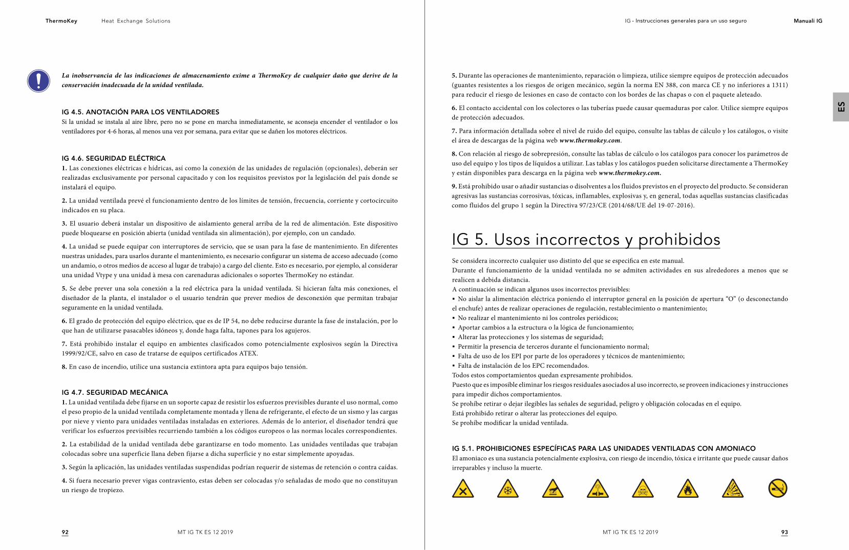
9392
Heat Exchange SolutionsThermoKey IG - Instrucciones generales para un uso seguro Manuali IG
ES
MT IG TK ES 12 2019MT IG TK ES 12 2019
La inobservancia de las indicaciones de almacenamiento exime a ThermoKey de cualquier daño que derive de la conservación inadecuada de la unidad ventilada.
IG 4.5. ANOTACIÓN PARA LOS VENTILADORESSi la unidad se instala al aire libre, pero no se pone en marcha inmediatamente, se aconseja encender el ventilador o los ventiladores por 4-6 horas, al menos una vez por semana, para evitar que se dañen los motores eléctricos.
IG 4.6. SEGURIDAD ELÉCTRICA1. Las conexiones eléctricas e hídricas, así como la conexión de las unidades de regulación (opcionales), deberán ser realizadas exclusivamente por personal capacitado y con los requisitos previstos por la legislación del país donde se instalará el equipo.
2. La unidad ventilada prevé el funcionamiento dentro de los límites de tensión, frecuencia, corriente y cortocircuito indicados en su placa.
3. El usuario deberá instalar un dispositivo de aislamiento general arriba de la red de alimentación. Este dispositivo puede bloquearse en posición abierta (unidad ventilada sin alimentación), por ejemplo, con un candado.
4. La unidad se puede equipar con interruptores de servicio, que se usan para la fase de mantenimiento. En diferentes nuestras unidades, para usarlos durante el mantenimiento, es necesario configurar un sistema de acceso adecuado (como un andamio, o otros medios de acceso al lugar de trabajo) a cargo del cliente. Esto es necesario, por ejemplo, al considerar una unidad Vtype y una unidad à mesa con carenaduras adicionales o soportes ThermoKey no estándar.
5. Se debe prever una sola conexión a la red eléctrica para la unidad ventilada. Si hicieran falta más conexiones, el diseñador de la planta, el instalador o el usuario tendrán que prever medios de desconexión que permitan trabajar seguramente en la unidad ventilada.
6. El grado de protección del equipo eléctrico, que es de IP 54, no debe reducirse durante la fase de instalación, por lo que han de utilizarse pasacables idóneos y, donde haga falta, tapones para los agujeros.
7. Está prohibido instalar el equipo en ambientes clasificados como potencialmente explosivos según la Directiva 1999/92/CE, salvo en caso de tratarse de equipos certificados ATEX.
8. En caso de incendio, utilice una sustancia extintora apta para equipos bajo tensión.
IG 4.7. SEGURIDAD MECÁNICA1. La unidad ventilada debe fijarse en un soporte capaz de resistir los esfuerzos previsibles durante el uso normal, como el peso propio de la unidad ventilada completamente montada y llena de refrigerante, el efecto de un sismo y las cargas por nieve y viento para unidades ventiladas instaladas en exteriores. Además de lo anterior, el diseñador tendrá que verificar los esfuerzos previsibles recurriendo también a los códigos europeos o las normas locales correspondientes.
2. La estabilidad de la unidad ventilada debe garantizarse en todo momento. Las unidades ventiladas que trabajan colocadas sobre una superficie llana deben fijarse a dicha superficie y no estar simplemente apoyadas.
3. Según la aplicación, las unidades ventiladas suspendidas podrían requerir de sistemas de retención o contra caídas.
4. Si fuera necesario prever vigas contraviento, estas deben ser colocadas y/o señaladas de modo que no constituyan un riesgo de tropiezo.
IG 5. Usos incorrectos y prohibidosSe considera incorrecto cualquier uso distinto del que se especifica en este manual.Durante el funcionamiento de la unidad ventilada no se admiten actividades en sus alrededores a menos que se realicen a debida distancia.A continuación se indican algunos usos incorrectos previsibles:§ No aislar la alimentación eléctrica poniendo el interruptor general en la posición de apertura “O” (o desconectando
el enchufe) antes de realizar operaciones de regulación, restablecimiento o mantenimiento;§ No realizar el mantenimiento ni los controles periódicos; § Aportar cambios a la estructura o la lógica de funcionamiento;§ Alterar las protecciones y los sistemas de seguridad;§ Permitir la presencia de terceros durante el funcionamiento normal;§ Falta de uso de los EPI por parte de los operadores y técnicos de mantenimiento;§ Falta de instalación de los EPC recomendados.
Todos estos comportamientos quedan expresamente prohibidos.Puesto que es imposible eliminar los riesgos residuales asociados al uso incorrecto, se proveen indicaciones y instrucciones para impedir dichos comportamientos.Se prohíbe retirar o dejar ilegibles las señales de seguridad, peligro y obligación colocadas en el equipo.Está prohibido retirar o alterar las protecciones del equipo.Se prohíbe modificar la unidad ventilada.
IG 5.1. PROHIBICIONES ESPECÍFICAS PARA LAS UNIDADES VENTILADAS CON AMONIACOEl amoniaco es una sustancia potencialmente explosiva, con riesgo de incendio, tóxica e irritante que puede causar daños irreparables y incluso la muerte.
5. Durante las operaciones de mantenimiento, reparación o limpieza, utilice siempre equipos de protección adecuados (guantes resistentes a los riesgos de origen mecánico, según la norma EN 388, con marca CE y no inferiores a 1311) para reducir el riesgo de lesiones en caso de contacto con los bordes de las chapas o con el paquete aleteado.
6. El contacto accidental con los colectores o las tuberías puede causar quemaduras por calor. Utilice siempre equipos de protección adecuados.
7. Para información detallada sobre el nivel de ruido del equipo, consulte las tablas de cálculo y los catálogos, o visite el área de descargas de la página web www.thermokey.com.
8. Con relación al riesgo de sobrepresión, consulte las tablas de cálculo o los catálogos para conocer los parámetros de uso del equipo y los tipos de líquidos a utilizar. Las tablas y los catálogos pueden solicitarse directamente a ThermoKey y están disponibles para descarga en la página web www.thermokey.com.
9. Está prohibido usar o añadir sustancias o disolventes a los fluidos previstos en el proyecto del producto. Se consideran agresivas las sustancias corrosivas, tóxicas, inflamables, explosivas y, en general, todas aquellas sustancias clasificadas como fluidos del grupo 1 según la Directiva 97/23/CE (2014/68/UE del 19-07-2016).
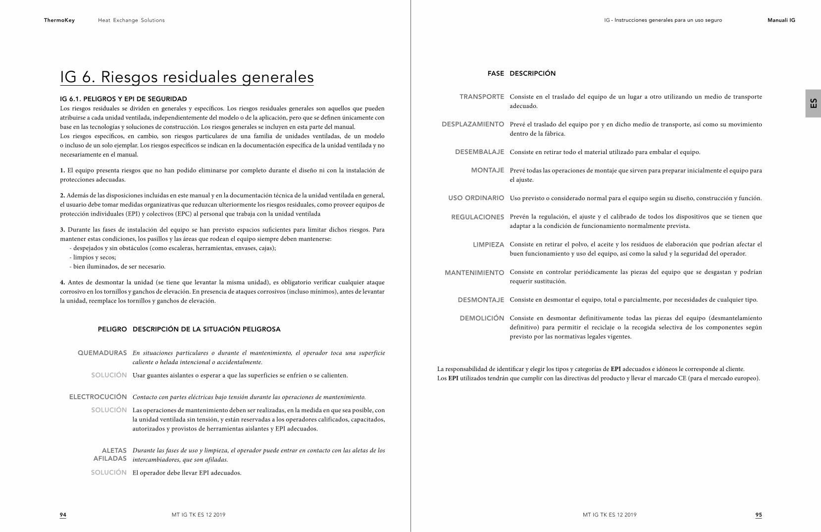
9594
Heat Exchange SolutionsThermoKey IG - Instrucciones generales para un uso seguro Manuali IG
ES
MT IG TK ES 12 2019MT IG TK ES 12 2019
IG 6. Riesgos residuales generalesIG 6.1. PELIGROS Y EPI DE SEGURIDADLos riesgos residuales se dividen en generales y específicos. Los riesgos residuales generales son aquellos que pueden atribuirse a cada unidad ventilada, independientemente del modelo o de la aplicación, pero que se definen únicamente con base en las tecnologías y soluciones de construcción. Los riesgos generales se incluyen en esta parte del manual.Los riesgos específicos, en cambio, son riesgos particulares de una familia de unidades ventiladas, de un modelo o incluso de un solo ejemplar. Los riesgos específicos se indican en la documentación específica de la unidad ventilada y no necesariamente en el manual.
1. El equipo presenta riesgos que no han podido eliminarse por completo durante el diseño ni con la instalación de protecciones adecuadas.
2. Además de las disposiciones incluidas en este manual y en la documentación técnica de la unidad ventilada en general, el usuario debe tomar medidas organizativas que reduzcan ulteriormente los riesgos residuales, como proveer equipos de protección individuales (EPI) y colectivos (EPC) al personal que trabaja con la unidad ventilada
3. Durante las fases de instalación del equipo se han previsto espacios suficientes para limitar dichos riesgos. Para mantener estas condiciones, los pasillos y las áreas que rodean el equipo siempre deben mantenerse:
- despejados y sin obstáculos (como escaleras, herramientas, envases, cajas);- limpios y secos;- bien iluminados, de ser necesario.
4. Antes de desmontar la unidad (se tiene que levantar la misma unidad), es obligatorio verificar cualquier ataque corrosivo en los tornillos y ganchos de elevación. En presencia de ataques corrosivos (incluso mínimos), antes de levantar la unidad, reemplace los tornillos y ganchos de elevación.
SOLUCIÓN
SOLUCIÓN
QUEMADURAS
ELECTROCUCIÓN
En situaciones particulares o durante el mantenimiento, el operador toca una superficie caliente o helada intencional o accidentalmente.
Usar guantes aislantes o esperar a que las superficies se enfríen o se calienten.
Contacto con partes eléctricas bajo tensión durante las operaciones de mantenimiento.
Las operaciones de mantenimiento deben ser realizadas, en la medida en que sea posible, con la unidad ventilada sin tensión, y están reservadas a los operadores calificados, capacitados, autorizados y provistos de herramientas aislantes y EPI adecuados.
Durante las fases de uso y limpieza, el operador puede entrar en contacto con las aletas de los intercambiadores, que son afiladas.
El operador debe llevar EPI adecuados.SOLUCIÓN
ALETAS AFILADAS
DESCRIPCIÓN DE LA SITUACIÓN PELIGROSAPELIGRO
La responsabilidad de identificar y elegir los tipos y categorías de EPI adecuados e idóneos le corresponde al cliente.Los EPI utilizados tendrán que cumplir con las directivas del producto y llevar el marcado CE (para el mercado europeo).
FASE DESCRIPCIÓN
TRANSPORTE
DESPLAZAMIENTO
DESEMBALAJE
MONTAJE
USO ORDINARIO
REGULACIONES
LIMPIEZA
MANTENIMIENTO
DESMONTAJE
DEMOLICIÓN
Consiste en el traslado del equipo de un lugar a otro utilizando un medio de transporte adecuado.
Prevé el traslado del equipo por y en dicho medio de transporte, así como su movimiento dentro de la fábrica.
Consiste en retirar todo el material utilizado para embalar el equipo.
Prevé todas las operaciones de montaje que sirven para preparar inicialmente el equipo para el ajuste.
Uso previsto o considerado normal para el equipo según su diseño, construcción y función.
Prevén la regulación, el ajuste y el calibrado de todos los dispositivos que se tienen que adaptar a la condición de funcionamiento normalmente prevista.
Consiste en retirar el polvo, el aceite y los residuos de elaboración que podrían afectar el buen funcionamiento y uso del equipo, así como la salud y la seguridad del operador.
Consiste en controlar periódicamente las piezas del equipo que se desgastan y podrían requerir sustitución.
Consiste en desmontar el equipo, total o parcialmente, por necesidades de cualquier tipo.
Consiste en desmontar definitivamente todas las piezas del equipo (desmantelamiento definitivo) para permitir el reciclaje o la recogida selectiva de los componentes según previsto por las normativas legales vigentes.
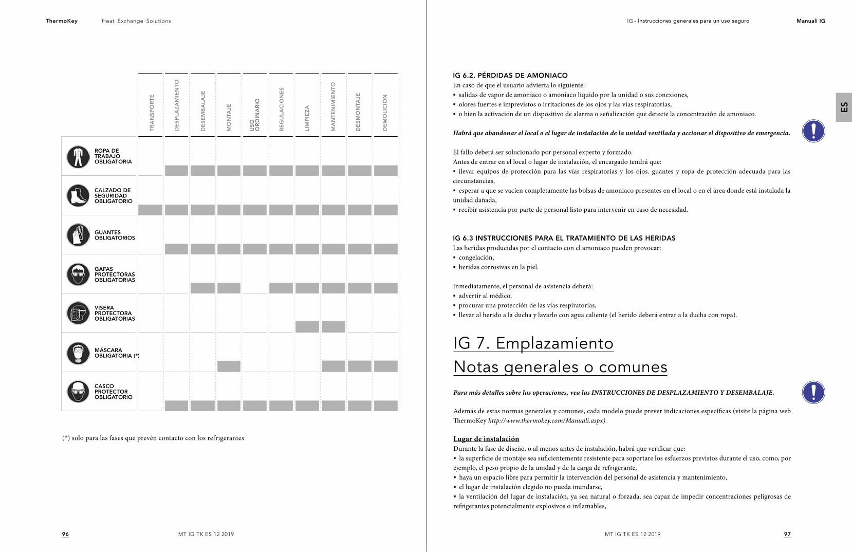
9796
Heat Exchange SolutionsThermoKey IG - Instrucciones generales para un uso seguro Manuali IG
ES
MT IG TK ES 12 2019MT IG TK ES 12 2019
ROPA DE TRABAJO OBLIGATORIA
VISERA PROTECTORA OBLIGATORIAS
CASCO PROTECTOR OBLIGATORIO
GUANTES OBLIGATORIOS
CALZADO DE SEGURIDAD OBLIGATORIO
MÁSCARA OBLIGATORIA (*)
GAFAS PROTECTORAS OBLIGATORIAS
TR
AN
SP
OR
TE
DE
SP
LAZ
AM
IEN
TO
DE
SE
MB
ALA
JE
MO
NTA
JE
RE
GU
LAC
ION
ES
LIM
PIE
ZA
MA
NT
EN
IMIE
NT
O
DE
SM
ON
TAJE
DE
MO
LIC
IÓN
US
O
OR
DIN
AR
IO
(*) solo para las fases que prevén contacto con los refrigerantes
IG 6.2. PÉRDIDAS DE AMONIACOEn caso de que el usuario advierta lo siguiente:§ salidas de vapor de amoniaco o amoniaco líquido por la unidad o sus conexiones,§ olores fuertes e imprevistos o irritaciones de los ojos y las vías respiratorias,§ o bien la activación de un dispositivo de alarma o señalización que detecte la concentración de amoniaco.
Habrá que abandonar el local o el lugar de instalación de la unidad ventilada y accionar el dispositivo de emergencia.
El fallo deberá ser solucionado por personal experto y formado.Antes de entrar en el local o lugar de instalación, el encargado tendrá que:§ ilevar equipos de protección para las vías respiratorias y los ojos, guantes y ropa de protección adecuada para las
circunstancias,§ esperar a que se vacíen completamente las bolsas de amoniaco presentes en el local o en el área donde está instalada la
unidad dañada,§ recibir asistencia por parte de personal listo para intervenir en caso de necesidad.
IG 6.3 INSTRUCCIONES PARA EL TRATAMIENTO DE LAS HERIDASLas heridas producidas por el contacto con el amoniaco pueden provocar:§ congelación,§ heridas corrosivas en la piel.
Inmediatamente, el personal de asistencia deberá:§ advertir al médico,§ procurar una protección de las vías respiratorias,§ llevar al herido a la ducha y lavarlo con agua caliente (el herido deberá entrar a la ducha con ropa).
IG 7. EmplazamientoNotas generales o comunesPara más detalles sobre las operaciones, vea las INSTRUCCIONES DE DESPLAZAMIENTO Y DESEMBALAJE.
Además de estas normas generales y comunes, cada modelo puede prever indicaciones específicas (visite la página web ThermoKey http://www.thermokey.com/Manuali.aspx).
Lugar de instalaciónDurante la fase de diseño, o al menos antes de instalación, habrá que verificar que:§ la superficie de montaje sea suficientemente resistente para soportare los esfuerzos previstos durante el uso, como, por
ejemplo, el peso propio de la unidad y de la carga de refrigerante,§ haya un espacio libre para permitir la intervención del personal de asistencia y mantenimiento,§ el lugar de instalación elegido no pueda inundarse,§ la ventilación del lugar de instalación, ya sea natural o forzada, sea capaz de impedir concentraciones peligrosas de
refrigerantes potencialmente explosivos o inflamables,
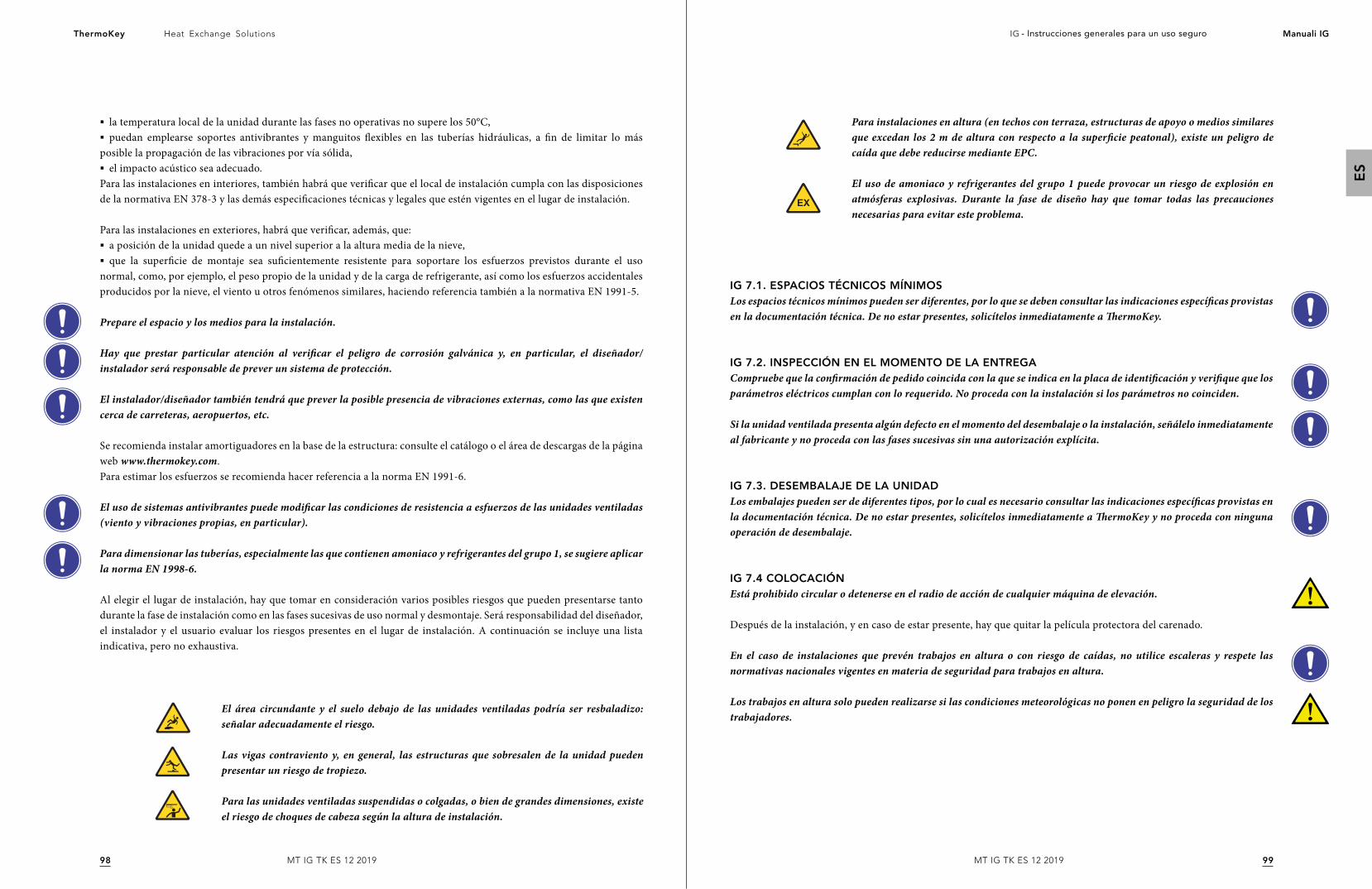
9998
Heat Exchange SolutionsThermoKey IG - Instrucciones generales para un uso seguro Manuali IG
ES
MT IG TK ES 12 2019MT IG TK ES 12 2019
§ la temperatura local de la unidad durante las fases no operativas no supere los 50°C,§ puedan emplearse soportes antivibrantes y manguitos flexibles en las tuberías hidráulicas, a fin de limitar lo más
posible la propagación de las vibraciones por vía sólida,§ el impacto acústico sea adecuado.
Para las instalaciones en interiores, también habrá que verificar que el local de instalación cumpla con las disposiciones de la normativa EN 378-3 y las demás especificaciones técnicas y legales que estén vigentes en el lugar de instalación.
Para las instalaciones en exteriores, habrá que verificar, además, que:§ a posición de la unidad quede a un nivel superior a la altura media de la nieve,§ que la superficie de montaje sea suficientemente resistente para soportare los esfuerzos previstos durante el uso
normal, como, por ejemplo, el peso propio de la unidad y de la carga de refrigerante, así como los esfuerzos accidentales producidos por la nieve, el viento u otros fenómenos similares, haciendo referencia también a la normativa EN 1991-5.
Prepare el espacio y los medios para la instalación.
Hay que prestar particular atención al verificar el peligro de corrosión galvánica y, en particular, el diseñador/instalador será responsable de prever un sistema de protección.
El instalador/diseñador también tendrá que prever la posible presencia de vibraciones externas, como las que existen cerca de carreteras, aeropuertos, etc.
Se recomienda instalar amortiguadores en la base de la estructura: consulte el catálogo o el área de descargas de la página web www.thermokey.com. Para estimar los esfuerzos se recomienda hacer referencia a la norma EN 1991-6.
El uso de sistemas antivibrantes puede modificar las condiciones de resistencia a esfuerzos de las unidades ventiladas (viento y vibraciones propias, en particular).
Para dimensionar las tuberías, especialmente las que contienen amoniaco y refrigerantes del grupo 1, se sugiere aplicar la norma EN 1998-6.
Al elegir el lugar de instalación, hay que tomar en consideración varios posibles riesgos que pueden presentarse tanto durante la fase de instalación como en las fases sucesivas de uso normal y desmontaje. Será responsabilidad del diseñador, el instalador y el usuario evaluar los riesgos presentes en el lugar de instalación. A continuación se incluye una lista indicativa, pero no exhaustiva.
El área circundante y el suelo debajo de las unidades ventiladas podría ser resbaladizo: señalar adecuadamente el riesgo.
Las vigas contraviento y, en general, las estructuras que sobresalen de la unidad pueden presentar un riesgo de tropiezo.
Para las unidades ventiladas suspendidas o colgadas, o bien de grandes dimensiones, existe el riesgo de choques de cabeza según la altura de instalación.
Para instalaciones en altura (en techos con terraza, estructuras de apoyo o medios similares que excedan los 2 m de altura con respecto a la superficie peatonal), existe un peligro de caída que debe reducirse mediante EPC.
El uso de amoniaco y refrigerantes del grupo 1 puede provocar un riesgo de explosión en atmósferas explosivas. Durante la fase de diseño hay que tomar todas las precauciones necesarias para evitar este problema.
IG 7.1. ESPACIOS TÉCNICOS MÍNIMOSLos espacios técnicos mínimos pueden ser diferentes, por lo que se deben consultar las indicaciones específicas provistas en la documentación técnica. De no estar presentes, solicítelos inmediatamente a ThermoKey.
IG 7.2. INSPECCIÓN EN EL MOMENTO DE LA ENTREGACompruebe que la confirmación de pedido coincida con la que se indica en la placa de identificación y verifique que los parámetros eléctricos cumplan con lo requerido. No proceda con la instalación si los parámetros no coinciden.
Si la unidad ventilada presenta algún defecto en el momento del desembalaje o la instalación, señálelo inmediatamente al fabricante y no proceda con las fases sucesivas sin una autorización explícita.
IG 7.3. DESEMBALAJE DE LA UNIDADLos embalajes pueden ser de diferentes tipos, por lo cual es necesario consultar las indicaciones específicas provistas en la documentación técnica. De no estar presentes, solicítelos inmediatamente a ThermoKey y no proceda con ninguna operación de desembalaje.
IG 7.4 COLOCACIÓNEstá prohibido circular o detenerse en el radio de acción de cualquier máquina de elevación.
Después de la instalación, y en caso de estar presente, hay que quitar la película protectora del carenado.
En el caso de instalaciones que prevén trabajos en altura o con riesgo de caídas, no utilice escaleras y respete las normativas nacionales vigentes en materia de seguridad para trabajos en altura.
Los trabajos en altura solo pueden realizarse si las condiciones meteorológicas no ponen en peligro la seguridad de los trabajadores.
101100
Heat Exchange SolutionsThermoKey IG - Instrucciones generales para un uso seguro Manuali IG
ES
MT IG TK ES 12 2019MT IG TK ES 12 2019
IG 8. INSTALACIÓNLa instalación es la fase sucesiva a la colocación de la unidad ventilada, en la cual se realizan las operaciones de fijación de la misma al soporte, se colocan los contravientos y se vuelven a montar los componentes desmontados para el desplazamiento.
La instalación debe realizarse en conformidad con el manual y con las indicaciones de la norma EN 378-3.
La fijación mecánica de la unidad ventilada está a cargo del instalador. La unidad ventilada prevé agujeros de fijación. Si las dimensiones de los agujeros fueran insuficientes, no debe aumentarlas sin la autorización de ThermoKey.
Los diámetros de los agujeros de fijación son el resultado de cálculos estáticos realizados por el fabricante; los elementos de fijación deben tomar en cuenta el diámetro de los agujeros.Los elementos de fijación deben dotarse de un medio idóneo que impida su aflojamiento.
Para poder dimensionar los dispositivos de anclaje o fijación de las unidades ventiladas, siga las normas ETAG de referencia y consulte los catálogos técnicos disponibles en el área de descargas de la página web www.thermokey.com.
Para mejorar la estabilidad a la carga del viento de la unidad instalada en exterior, es posible utilizar vigas contraviento. La elección y el dimensionamiento de las vigas contraviento están a cargo del instalador.
IG 9. Conexiones frigoríficas e hidráulicasEstá absolutamente prohibido adaptar la posición de los colectores a la línea de suministro; los colectores no pueden moverse de su posición original.
§ Al colocar las conexiones de las tuberías de entrada y salida, es obligatorio comprobar la indicación del flujo de refrigerante señalada en los manguitos o en las bridas. § Se recomienda instalar válvulas de interceptación arriba para facilitar las operaciones de mantenimiento. Si la instalación de
dichas válvulas conlleva algún riesgo, será responsabilidad del instalador adoptar soluciones adecuadas en los circuitos.§ Para los condensadores y los enfriadores secos equipados con sistemas adiabaticos, es obligatorio vaciar el agua del
sistema de alimentación para evitar la formación de hielo si se prevé una temperatura ambiental inferior a 0°C.§ Es obligatorio respetar los diámetros de las uniones previstas al efectuar las conexiones frigoríficas e hidráulicas.
Cualquier intervención tendrá que ser previamente autorizada por la Oficina de Asistencia al Cliente de ThermoKey; de no ser así, la empresa quedará exenta de cualquier responsabilidad por daños a personas, animales o cosas, así como por prestaciones inferiores a las declaradas, y las condiciones de garantía perderán su validez.
IG 9.1. CONEXIONES H IDRÁULICASLas conexiones hidráulicas deben realizarse respetando las normativas nacionales o locales; las tuberías pueden ser de acero, acero galvanizado o PVC. Las tuberías se deben dimensionar adecuadamente en función del caudal nominal del refrigerante, la presión, las pérdidas de carga del circuito hidráulico y las temperaturas de trabajo. Todas las conexiones hidráulicas deben realizarse utilizando material de celdas cerradas con grosor adecuado.
IG 9.2. MONTAJE DE LAS TUBERÍAS§ Fije correctamente todas las tuberías y evite daños mecánicos siguiendo las prácticas de montaje correctas y las indicaciones
ofrecidas en las especificaciones técnicas, que están disponibles en el área de descargas de la página web www.thermokey.com.§ Durante el ajuste, sostenga las tuberías para no esforzar inadecuadamente los sistemas de fijación.§ Si la instalación se realiza en áreas donde se permite el tránsito del personal, coloque las tuberías de modo que no
obstaculicen el paso y compruebe que estén unidas con racores que no puedan quitarse con facilidad.§ Utilice dispositivos de fijación aptos para el peso de las tuberías para que todo el peso no recaiga sobre las conexiones,
provocando que se rompan y se desprendan de la unidad.
En las unidades ventiladas que usan amoniaco o líquidos explosivos o inflamables, una instalación incorrecta de las tuberías conlleva un riesgo de derrame del refrigerante.
IG 9.3. SOLDADURA§ Para las operaciones de conexión mediante soldadura, habrá que soldar con precisión y atención para evitar pérdidas,§ evite el sobrecalentamiento durante la soldadura (peligro de redimensionamiento excesivo),§ use gas de protección durante la soldadura (evite incrustaciones excesivas),§ los trabajos de soldadura en componentes presión pueden causar incendios o explosiones,§ realice los trabajos de soldadura solamente con la unidad descargada y sin presión,§ compruebe que las cargas y las vibraciones no produzcan esfuerzos de la unidad,§ al soldar las conexiones, está prohibido dirigir la llama hacia la unidad u otros equipos eléctricos instalados.
IG 10. Conexión eléctricaLas conexiones eléctricas deben realizarse en conformidad con este manual y con los esquemas eléctricos provistos en las instrucciones y los datos técnicos, así como con las normas aplicables a las instalaciones eléctricas en el país de instalación de la unidad.
Es obligatorio conectar al equipo a tierra.
§ Las operaciones de conexión eléctrica deben ser realizadas por personal capacitado y con los requisitos técnicos previstos por el país de instalación de la unidad. § Es obligatorio comprobar que la tensión de línea coincida con el valor indicado en la placa de identificación.§ La elección y el dimensionamiento del cable de alimentación de la unidad ventilada están a cargo del diseñador/instalador.§ Al colocar el cable de alimentación, se recomienda usar canalizaciones o tuberías que lo protejan mecánicamente. Se
desaconseja absolutamente la colocación libre en el suelo sin fijación.§ Es obligatorio utilizar cables de alimentación de tipo y sección mínima conformes a la norma EN 60204-1 y, en su caso,
a las normas técnicas vigentes en el país de instalación.§ Las potencias y absorciones para dimensionar el cable eléctrico de la red están disponibles en la placa de identificación
y/o los catálogos técnicos.§ Es obligatorio equipar la instalación de alimentación eléctrica con un dispositivo de protección contra los excesos de
corriente - por ejemplo, un interruptor magnetotérmico – y de tensión. § El cable eléctrico debe llegar a los cuadros y a las cajas eléctricas de la unidad ventilada por abajo, o bien de modo que
se reduzca el riesgo de filtración de agua en su interior, y siempre es necesario utilizar prensacables.
103102
Heat Exchange SolutionsThermoKey IG - Instrucciones generales para un uso seguro Manuali IG
ES
MT IG TK ES 12 2019MT IG TK ES 12 2019
§ La protección contra contactos eléctricos indirectos se realiza por medio de la conexión a tierra de la estructura metálica de la unidad ventilada y la coordinación con interruptores automáticos para los sistemas de distribución TT y TN-S.
IG 11. RefrigerantesToda la información contenida en este párrafo es general y no sustituye a la que se indica en las fichas técnicas y de seguridad del refrigerante utilizado.
Consulte siempre la información que se indica en las fichas de seguridad del refrigerante.
IG 11.1 AMONIACO COMO LÍQUIDO REFRIGERANTE§ El amoniaco es tóxico para el aparato respiratorio,§ una exposición prolongada o severa a vapores de amoniaco puede provocar ulceraciones en la conjuntiva y la córnea,
edema en la glotis, broncoespasmos, edema pulmonar y paro respiratorio,
IG 12. Unidades ventiladas inspeccionablesLas unidades ventiladas inspeccionables permiten acceder al compartimiento de los ventiladores sin desmontarlos completamente. Esta función opcional requiere de medidas técnicas adicionales descritas en las especificaciones técnicas, disponibles en el área de descargas de la página web www.thermokey.com.
Para las unidades ventiladas inspeccionables en las que la opción (ej. enclavamientos eléctricos, etc.) esté a cargo del instalador, la seguridad y la conformidad final de la unidad ventilada con las normas legales se garantiza sola y exclusivamente al completar la instalación según indicado por ThermoKey.
§ el amoniaco es altamente irritante para las mucosas oculares y, con presencia de humedad, también para la piel,§ las salpicaduras de amoniaco líquido pueden causar quemaduras por frío o por su acción cáustica,§ el amoniaco puede ser peligroso para el ambiente acuático, especialmente para los peces.
IG 11.2 INDICACIONES DE PELIGRO (H) Y PRUDENCIA (P)Toda la información de peligro y prudencia se indica en el reglamento CE 1272/2008. A continuación se ofrecen solamente algunos ejemplos:
PeligroH221: Gases inflamables. H331: Tóxico en caso de inhalación. H314: Provoca quemaduras graves en la piel y lesiones oculares graves. H400: Muy tóxico para los organismos acuáticos. EUH071: Corrosivo para las vías respiratorias.PrudenciaP210: Mantener alejado de fuentes de calor, chispas, llama abierta o superficies calientes. – No fumar.P280: Llevar guantes/prendas/gafas/máscara de protección. P260: No respirar los vapores. P273: Evitar su liberación al medio ambiente. P377: En caso de incendio por fuga de gas, no apagar, salvo si la fuga puede detenerse sin peligro.P381: Eliminar todas las fuentes de ignición. P303+P361+P353+315: EN CASO DE CONTACTO CON LA PIEL (O EL CABELLO): Quitarse inmediatamente las prendas contaminadas. Aclararse la piel con agua/ducharse. Consultar a un médico inmediatamente. P304+P340+P315: EN CASO DE INHALACIÓN: Transportar a la víctima al exterior y mantenerla en reposo en una posición cómoda para respirar. Consultar a un médico inmediatamente. P305+P351+P338+P315: EN CASO DE CONTACTO CON LOS OJOS: Aclarar cuidadosamente con agua durante varios minutos. Quitar las lentes de contacto, si lleva y resulta fácil. Seguir aclarando. Consultar a un médico inmediatamente.
§ Cerca de los bornes de alimentación al cuadro eléctrico, el hilo amarillo/verde de conexión a tierra debe quedar más largo que los demás conductores para garantizar que, en caso de tracción del cable, éste sea el último en desconectarse de los bornes. § La línea de alimentación se conecta al cuadro general en los modelos trifásicos y monofásicos.§ En caso de montar varias unidades ventiladas en serie, estas tienen que incluirse en un sistema equipotencial:
la conexión debe realizarse por medio de un borne marcado con el símbolo colocado en la chapa del lado de los colectores. La sección de este conductor (de color amarillo/verde) debe ser igual o mayor que la sección máxima del cable de alimentación.§ Para las conexiones eléctricas de los ventiladores donde no haya cuadro eléctrico, es obligatorio consultar el esquema
eléctrico indicado en la caja de derivación de los ventiladores. Se recomienda conectar en serie los termocontactos TK para la gestión de las alarmas. § Si la unidad está provista de un sistema de regulación (reguladores de revoluciones o ventiladores electrónicos CE), antes
de conectar la unidad a la red de distribución hay que garantizar el respeto de las normativas EN 61000-3-2 y EN 61000-3-12.§ Utilice exclusivamente reguladores de revoluciones por inverter suministrados por ThermoKey. El uso de inverter de
otras marcas tiene que ser aprobado por la oficina técnica de ThermoKey.
Instructions générales pour une utilisation sûre
Le Système de Gestion de la Qualité est certifié
en conformité à la norme ISO 9001
Le Système de Gestion de l'Environnement est
certifié en conformité à la norme ISO 14001
Le Système de Gestion de la Securité est certifié
en conformité à la norme OHSAS 18001
LA VERSION ORIGINALE DES PRESENTES INSTRUCTIONS EST REDIGEE EN ITALIEN
MT IG TK FR 12 2019F
R
106105
Heat Exchange SolutionsThermoKey IG - Instructions générales pour une utilisation sûre Manuels IG
FR
MT IG TK FR 12 2019MT IG TK FR 12 2019
LIRE ATTENTIVEMENT ET COMPRENDRE ENTIÈREMENT TOUTES LES INFORMATIONS CONTENUES DANS LES PRÉSENTES INSTRUCTIONS AVANT LA PHASE DE CONCEPTION ET, DANS TOUS LES CAS, AVANT D’EFFECTUER TOUTE OPÉRATION DE DÉPLACEMENT, DE DÉSEMBALLAGE, DE MONTAGE, DE MISE EN PLACE ET DE MISE EN SERVICE DE L’APPAREIL.
Le Constructeur décline toute responsabilité pour tout dommage causé à des personnes ou à des biens résultant de la non-observation des présentes instructions.
L’original du présent manuel est en italien et il se trouve sur le site Internet www.thermokey.comLa traduction du manuel en anglais est conforme à l'original et elle se trouve également sur le site Internet: www.thermokey.comLes traductions réalisées peuvent contenir des erreurs. En cas de doutes, référez-vous toujours à la version originale rédigée en italien ou à sa traduction en anglais.
Heat Exchange SolutionsThermoKey
LA PHILOSOPHIE DU PRESENT MANUEL
Le paragraphe n°255 du guide pour l'application de la 2ème révision de la directive Machines 2006/42/CE suggère de mettre à disposition les instructions sous format électronique sur Internet pour éviter de les perdre et pour faciliter leur mise à jour.En outre, le paragraphe 275 exige que le manuel et les documents technico-commerciaux, dont les catalogues, soient cohérents.La plupart des unités ventilées produites par ThermoKey sont personnalisées pour une installation ou un client spécifique.En se fondant sur les motifs indiqués ci-dessus et en considérant que les lecteurs de cette notice d'instructions sont les concepteurs des installations, les installateurs et, enfin, les utilisateurs, la documentation technique pour la conception et l'utilisation correctes de l'unité ventilée, en accord avec sa philosophie, se compose d'une série de documents qui, réunis, sont définis comme le MANUEL.
INSTRUCTIONS GENERALES POUR UNE UTILISATION SURE (IG)
INSTRUCTIONS POUR LA MANUTENTION ET LE DESEMBALLAGE (IM)
INSTRUCTIONS ET DONNEES TECHNIQUES (TC)
INSTRUCTIONS SPECIFIQUES D'UTILISATION ET D'ENTRETIEN (IS)
LA STRUCTURE DU MANUEL EST INDIQUÉE CI-DESSOUS :
108107
Heat Exchange SolutionsThermoKey IG - Instructions générales pour une utilisation sûre Manuels IG
FR
MT IG TK FR 12 2019MT IG TK FR 12 2019
Les Instructions Générales pour une Utilisation sûre donnent les informations relatives à la sécurité et à une utilisation correcte incluant :
IG 1. NOTES PRELIMINAIRESG 2.1 REMARQUES DU LOGICIEL ARCHIMEDE
IG 2. NOTES LEGALESIG 2.1 VERSION ORIGINALE
IG 2.2 RESTRICTIONS D'UTILISATION DU PRESENT MANUEL
IG 2.3 CONTENU ET COMPREHENSION DU MANUEL
IG 2.4 RESPONSABILITES
IG 2.5 DISPOSITIONS LEGALES ET TECHNIQUES EMPLOYEES DANS LA CONSTRUCTION DE L'UNITE
IG 2.6 IMPORTANCE DE LA SERIE DE NORMES EN 378
IG 3. PLAQUES ET ETIQUETTES GENERALES
IG 4. AVERTISSEMENTS GENERAUX ET NORMES DE SECURITEIG 4.1 GENERALITES
IG 4.2 MANUTENTION, CHARGEMENT ET DECHARGEMENT
IG 4.3 TRANSPORT
IG 4.4 STOCKAGE
IG 4.5 NOTE POUR LES VENTILATEURS
IG 4.6 SECURITE ELECTRIQUE
IG 4.7 SECURITE MECANIQUE
IG 5. UTILISATIONS INCORRECTES ET INTERDITESIG 5.1 INTERDICTIONS SPECIFIQUES POUR LES UNITES VENTILEES A L'AMMONIAC
IG 6. RISQUES RESIDUELS GENERAUXIG 6.1 RISQUES ET EPI DE SÉCURITÉ
IG 6.2 FUITES D'AMMONIAC
IG 6.3 INSTRUCTIONS POUR LES SOINS SUITE A DES BLESSURES
IG 7. MISE EN PLACE – NOTES GENERALES ET COMMUNESIG 7.1 ESPACES TECHNIQUES MINIMAUX
IG 7.2 INSPECTION A LA LIVRAISON
IG 7.3 DESEMBALLAGE DE L'UNITE
IG 7.4 MISE EN PLACE
IG 8. INSTALLATION
IG 9. RACCORDS FRIGORIFIQUES ET HYDRAULIQUESIG 9.1 RACCORDS HYDRAULIQUES
IG 9.2 MONTAGE DES TUYAUX
IG 9.3 SOUDAGE
IG 10. CONNEXION ELECTRIQUE
INDICE
109110
112112
112
112
113
115
115
115
115115
116
116
106
117
117
117
118119
119119
122
122
122124
124
124
124
125
115125
126
126
126
§ La section Instructions de Manutention et de Désemballage présente, au moyen de schémas numérotés, les opérations nécessaires et autorisées à la manutention et au désemballage des différentes unités ventilées. Dans le cas des unités ventilées spécifiques, les informations correctes seront identifiées dans le document par le numéro de confirmation de commande.
Afin de faciliter la mise à jour des informations et de lever toute ambigüité, cette partie de la documentation de l'unité ventilée est constituée des catalogues et de toute autre documentation technique fournie directement par ThermoKey et/ou disponible sur le site Internet www.thermokey.com.
§ Dans le chapitre Instructions et Données techniques (IT), les informations techniques pertinentes sont reportées pour chaque type d'unité ventilée. Celles-ci sont regroupées en plusieurs familles et incluent:
- LES DIMENSIONS ET LES POIDS
- ENCOMBREMENT ET ESPACES TECHNIQUES MINIMAUX
- DONNEES AERAULIQUES, ELECTRIQUES ET SUR LES PERFORMANCES
- LE NIVEAU D'EMISSIONS SONORES
- SCHEMAS ELECTRIQUES
- NOTICE TECHNIQUE
§ Les Instructions Spécifiques pour l'Utilisation et l'Entretien sont une partie spécifique à chaque modèle et éventuellement à chaque unité ventilée spécifiquement et elles comprennent :
IS 1 - INSTRUCTIONS DE FONCTIONNEMENT
IS 2 - PROBLEMES DE FONCTIONNEMENT
IS 3 - ENTRETIEN
IS 4 - PIECES DETACHEES
IG 11. REFRIGERANTSIG 11.1 L'AMMONIAC COMME FLUIDE REFRIGERANT
IG 11.2 INDICATIONS DE DANGER H ET PRUDENCE P
IG 12. UNITES VENTILEES POUVANT ETRE INSPECTEES
127127
128
128
110109
Heat Exchange SolutionsThermoKey IG - Instructions générales pour une utilisation sûre Manuels IG
FR
MT IG TK FR 12 2019MT IG TK FR 12 2019
IG 1. Notes préliminairesL'UNITÉ DEVRA ÊTRE DESTINÉE UNIQUEMENT À L’UTILISATION POUR LAQUELLE ELLE A ÉTÉ EXPRESSÉMENT CONÇUE, INDIQUÉE DANS LE PARAGRAPHE « NOTES PRÉLIMINAIRES ».
1. Les présentes notes préliminaires constituent une partie essentielle de ce manuel et elles doivent donc être lues avec la plus grande attention et bien comprises.
2. Le présent manuel fait partie de la documentation technique de l'unité ventilée. Il peut être complété par d'autres indications et partiellement modifié en fonction des personnalisations ou des conditions opérationnelles hors standard. En général, le manuel se compose d'une partie principale et de quelques annexes techniques. Par la suite, pour plus de simplicité, on se référera, lorsque cela n'est pas autrement spécifié, au manuel en englobant toute la documentation technique nécessaire à l'utilisation correcte de l'unité ventilée.
3. Il faut conserver ce manuel d’instructions pendant toute la durée de vie de l'unité ventilée.
4. Accordez une attention particulière aux normes d’utilisation présentes dans ce manuel car en cas de non-respect, l'unité ventilée et/ou les personnes, les animaux ou les biens peuvent subir des dommages.
5. ThermoKey réserve le droit de modifier le présent manuel à tout moment ; les révisions dans leur version mise à jour sont toujours rendues publiques sur le site www.thermokey.com. Afin de vérifier que vous êtes bien en possession de la dernière révision, vous devez consulter l'index de révision.
6. Les données du constructeur et la référence au numéro de commande du client sont reportées sur la plaque d'identification de l'unité ventilée qui contient, outre les données de l'unité ventilée elle-même, le numéro de commande.
7. Les pièces qui ne seraient pas originales doivent être préalablement approuvées par ThermoKey.
8. L'unité ventilée est conforme aux exigences essentielles de santé et de sécurité de la directive 2006/42/CE applicables pour tout ce qui est prévu dans les conditions d'utilisation standards ou convenues avec le client.
9. Toutes les utilisations non prévues et non décrites dans le présent manuel e/ou qui n'auraient pas été convenues entre l'utilisateur et ThermoKey préalablement à la construction/mise en service de l'unité ventilée sont explicitement interdites. Tout usage impropre de l'unité ventilée sont susceptibles de créer des conditions dangereuses, sur les conséquences desquelles ThermoKey n'assume aucune responsabilité.
10. L'unité ventilée a été prévue pour être employée uniquement avec les réfrigérants indiqués sur la commande identifiée par le numéro reporté sur la plaque d'identification.
11. Il est interdit d'utiliser des fluides réfrigérants différents de ceux qui ont été explicitement indiqué.
12. Pour l'utilisation d'ammoniac et de réfrigérants du groupe 1, des recommandations et des indications d'utilisation ultérieures peuvent être nécessaires par rapport à celles reportées dans les présentes instructions mais qui, dans tous les cas, sont contenues dans le manuel de l'unité ventilée.
La référence au numéro de commande est très importante car elle permet d'identifier les éventuelles personnalisations et les restrictions en matière d'utilisation convenues entre ThermoKey en qualité de constructeur et le client en qualité d'utilisateur.
13. Il est interdit d’utiliser des substances ou des fluides pouvant détériorer, rendre le fonctionnement incertain ou diminuer les rendements de l'unité ventilée.
14. Toutes les données techniques des unités ventilées ainsi que toutes les restrictions liées à l'utilisation et les caractéristiques minimales que doit posséder le site d'installation sont indiquées sur les catalogues techniques.
15. Dans le cas où des modifications ou des changements étaient rendues nécessaires sur l'unité ventilée après sa construction mais avant sa mise en service, ou bien si les conditions opérationnelles du site d'installation ne correspondaient pas aux conditions prévues, ou, dans tous les cas, si une différence existait entre ce qui avait été prévu avant la construction et l'état de fait du site d'installation, ThermoKey doit être contactée immédiatement et, dans tous les cas, avant d'effectuer toute intervention ou modification. Dans le cas contraire, ThermoKey ne pourra aucunement être tenue responsable.
16. Il incombe au concepteur, à l'installateur et/ou à l'utilisateur de respecter scrupuleusement les normes et les règlements locaux en ce qui concerne l'installation, l'utilisation et l'élimination de l'unité ventilée.
17. Par personnel qualifié, à moins que ce ne soit spécifié autrement dans le présent manuel, on doit toujours entendre une personne informée de manière appropriée ou surveillée par une personne dont la formation, la connaissance et l’expérience lui permettent d'exécuter le travail dans les règles de l'art, de percevoir les risques et d’éviter les dangers qui peuvent en découler.
18. Pour les Conditions de Garantie, référez-vous aux accords convenus en phase de commande.
19. Toute reproduction totale ou partielle de ce manuel est interdite sans l’autorisation écrite du constructeur. Des copies mises à jour du présent manuel sont disponibles sur le site www.thermokey.com
IG 1.1. REMARQUES DU LOGICIEL ARCHIMEDE1. La tension se réfère aux données nominales du founisseur: la consommation des ventilateurs peut varier en fonction de la température de l’air et de la tension réelle.
2. L’appareil peut ne pas être approprié à une ambiance très corrosive. Pour des applications spéciales, merci de contacter ThermoKey. Si un matériau d’ailettes spécial est sélectionné (cuivre, verni), tous les autres matériaux de l’appareil restent standard (pour plus d’informations, merci de consulter la description technique de l’appareil).
3. Les dimensions et le poids ne sont pas valables pour toutes les options possibles! Les dimensions hors tout de la fiche technique se rapportent aux appareils sans régulation/coffrets électriques. (Pour plus d’informations, merci de vous reporter au manuel du coffret électrique). Dans le cas d’appareils avec flux d’air horizontaux, la position standard des connexions est à gauche en regardant la batterie.
4. Le bruit causé par les systèmes de contrôle, système adiabatique..etc n’est pas considéré dans la déclaration de bruit des ventilateurs. Les valeurs réelles peuvent aussi subir des déviations dues aux conditions de l’installation.
5. Le manuel est consitué de 4 parties IG= instructions générales, IM = Instructions de manipulation et déballage, TC= Instructions et données techniques, IS = Instructions spécifiques d’utilisation et d’entrétien. Si pas expréssement demandé en phase de commande, les instructions TC et IS doivent être déchargées par l’utilisateur du site www.thermokey.com et elles ne seront pas fournies sur format papier. L’installeur doit suivre les indications des manuels ci-dessus et tous les manuels des principales composantes électriques (par ex . Ventilateurs, pompes, régulateurs…).
6. L’appareil est équipé de ventilateurs qui répondent aux exigences d’efficacité de la directive ERP 2009/125/EC

112111
Heat Exchange SolutionsThermoKey IG - Instructions générales pour une utilisation sûre Manuels IG
FR
MT IG TK FR 12 2019MT IG TK FR 12 2019
IG 2. Notes légalesIG 2.1. VERSION ORIGINALELa version originale du présent manuel est en italien et elle accompagne chaque traduction officielle. Les traductions du manuel non autorisées par le constructeur ne sont pas retenues comme étant en cours de validité.
L'utilisation de copies et/ou de traductions du présent manuel non autorisées et/ou l'emploi de traductions sans la version originale en italien exonèrent ThermoKey de toutes les conséquences et de toutes les responsabilités possibles pouvant en découler en cas d'incident.
IG 2.2. RESTRICTIONS D'UTILISATION DU PRESENT MANUELLe présent manuel d'utilisation et d'entretien a été rédigé pour les unités ventilées destinées au marché communautaire européen qui arborent le marquage CE.
Le présent manuel d'utilisation et d'entretien ne couvre pas l'introduction sur le marché et/ou l'utilisation des unités dans les pays non membres de l'Union européenne.
IG 2.3 CONTENU ET COMPREHENSION DU MANUELDans le cas où le concepteur, l'installateur et/ou l'utilisateur (dans des termes généraux et globaux les opérateurs) ne trouvaient pas dans le présent manuel les informations techniques nécessaires à l'installation, à l'utilisation, à l'entretien et/ou à l'élimination sûre de l'unité ou qu'ils avaient des doutes concernant les modalités correctes d'installation, d'utilisation, d'entretien et/ou d'élimination, ils sont invités à contacter directement ThermoKey. Le présent manuel d'utilisation et d'entretien a été rédigé afin d'être le plus complet et le plus clair possible, en lien à la préparation et aux
7. Conformément à la norme EN 13487, le niveau de pression sonore déclaré pour cet appareil a été calculé en conditions de champ libre sur un plan réfléchissant avec surface de référence parallélépipèdique. En référence à la norme ISO 3744, quand la différence de mesure entre l’appareil en fonctionnement et à l’arrêt est <= 6dB(A), la mesure sonore n’atteint pas la précision prévue par la norme. Les valeurs de bruit de fond inférieures à 30dB(A) sont typiques des environnements intérieurs et silencieux. La délclaration de la pression acoustique de l’appareil, déclarée sur les fiches techniques ThermoKey, considère le bruit de fond comme négligeable.
8. S x x x x : code sérial identificatif de la combinaison des options standard sélectionnables sur Archimede (mentionnées et décrites dans la séction ACCESSOIRES) et spéciales sur demande. Le code est affiché sur l’accusé de réception (comme partie intégrante du code de description du modèle) et il est présent sur l’étiquette données techniques du produit. A noter: pour chaque gamme les options disponbiles sont listées sur le catalogue sur le Tableau Options et Accessoires. Le registre des combinaisons et des options associées au code S x x x x peut être consulté sur demande.
9. La livraison des appareils standard est considérée franco usine. Pour des conditions ou termes spéciaux (par ex. Grandes quantités, spécifications spéciaux) merci de contacter le Sales dept.
10. L’appareil standard n’est pas autovideangeable: le choix du fluide (eau/glycole) est étroitement lié au point de congélation de celle-ci et à la période de fonctionnement réelle de l’appareil. Pour une construction autovindeangeable, merci de contacter ThermoKey pour une offre spéciale.
11. La portée d’air déclarée dans les fiches techniques représente la distance au ventilateur où la vitesse de l’air correspond à 0,25m/s. La portée d’air se réfère seulement au débit d’air par défaut du ventilateur: pour les modèles cubiques, light cubic et commerciaux avec câblage triangle ou monophasé, pour les modèles double flux avec connexion définie par la gamme.
12. Le dimensionnement se fait par une simulation du programme de sélection qui ne tient pas en compte l’influence des conditions d’installation.
13. Pour le choix de la pression maximale de fonctionnement, on considère le point moyen de la pression associé à la température de condensation.
14. Pour appareils avec ventilateurs et batteries microcanaux, il faut suivre les procédures disponibles sur le site ThermoKey (Indications for the use of TK micro cores).
15. Groupe de fluide rélatif à la directive 2014/68/CE.
16. Les données écrites sur l’étiquette des ventilateurs, ne representent pas les pires conditions d’absorption.
17. Les performances déclarées sont appropriées aux applications HVAC, avec flux d’air en champ libre côté batterie et ventilateur (par exemple la recirculation ou tout élément qui réduit le débit d’air doit être évité) et avec des températures d’entrée uniformes dans la batterie (par exemple, éviter les conditions dans lesquelles les éléments adjacents sont à l'origine des variations de températures à l’entrée de l’appareil). Pour d’autres applications critiques (par example industrielles etc...) merci de contacter ThermoKey.
18. ThermoKey se réserve le droit de modifier à tout moment, sans préavis, les données techniques, les plans et les pix du logiciel Archimede. Veuillez vous reporter à la version du logiciel et l’EULA du logiciel directement dans la section “’?”.
19. Le logiciel Archimede est basé sur les dernières librairies d’huiles, réfrigérants et mélanges de Refprop. Les mises à jour des données peuvent entaîner des performances différentes ds appareils par rapport à celles des versions précédentes d’Archimede.
20. Pay attention that the overall dimensions and weight of the unit equipped with EPS system, indicated in the technical sheet, refer to the model without electrical part and mounted evaporative panels, for variation of the possible option combinations please refer back to the following indications!Take into consideration that the evaporative modules mounted on the side of the model protrude of 440mm all together on the width of the model footprint, whereas they do not affect the length and height dimensions of the model, moreover the discharging tubes mounted on the models protrude of extra 320mm all together on the width of the model. Take into consideration that the control panels and connection piping protrude depending on the selected and requested combinations of 400mm from the extremities of the model.Consider as 60 kilos each module (per fan) the operative weight of the evaporative modules mounted with wet panels. Pay attention that in the case of non optimal maintenance of the discharging drip-trays or of the discharging line, you should consider a possible store of water in the tray and of the sole discharging pipes of EPS system of about 30 kilos per module (per fan). Consider the pre-mounted connection piping of EPS system to water supply network on the model of about 25 kilos per unit. Consider weight of the possible pre-mounted control electrical panel of the EPS system on the model of about 35 kilos per unit.
114113
Heat Exchange SolutionsThermoKey IG - Instructions générales pour une utilisation sûre Manuels IG
FR
MT IG TK FR 12 2019MT IG TK FR 12 2019
compétences de ses utilisateurs. En cas de non-compréhension du contenu du présent manuel ou d'une compréhension incomplète des indications données, il faut interrompre immédiatement toute phase de conception, d'installation, d'utilisation, d'entretien et/ou d'élimination de l'unité elle-même.
Si jamais les opérateurs poursuivaient leur activité sans avoir parfaitement et entièrement compris le présent manuel d'utilisation et d'entretien et/ou sans être en possession de toutes les connaissances et les indications nécessaires au déroulement de leur activité, ThermoKey se considère exonérée de toute conséquence ou responsabilité en découlant.
ThermoKey considère comme de la négligence le fait de ne pas signaler toute erreur, omission, erreur typographique, incohérence, etc. du présent manuel en lien avec les instructions et les indications techniques : le concepteur, l'installateur et l'utilisateur (les techniciens d’entretien) doivent immédiatement signaler à ThermoKey les situations qui seraient susceptibles de nuire à la sécurité des personnes, des biens et de l'environnement en agissant avec toute la compétence, le professionnalisme, l'esprit de collaboration et la diligence nécessaires.
Tout comportement négligent, peu prudent ou prouvant des compétences technico-professionnelles insuffisantes exonèrent le constructeur de toutes les conséquences et les responsabilités possibles qui pourraient en découler.
IG 2.4. RESPONSABILITEResponsabilité du constructeurLe constructeur est responsable de la conception, de la construction, du test et de l'emballage de l'unité ventilée aux fins de l'introduction sur le marché de l'Union européenne. Le constructeur garantit que l'unité ventilée est conçue, construite, testée et emballée dans le respect des exigences essentielles fixées dans les directives communautaires applicables et qu'une évaluation opportune de conformité dans ce sens a été effectuée.Les phases de retrait de l'emballage, de l'installation, de la mise en service, de l'entretien, du démontage et de l'élimination ne sont pas à la charge du constructeur, qui fournit dans les présentes instructions le maximum d'informations utiles pour les phases de vie précitées de l'unité ventilée.Toutes les parties de l'unité ont été conçues, réalisées et contrôlées afin de pouvoir supporter les sollicitations raisonnablement prévisibles dans l'utilisation prévue et dans tout ce qui est raisonnablement prévisible : aucune garantie de sécurité et/ou de fonctionnement ne peut être donnée si les unités sont employées dans des conditions d'utilisation non explicitement prévues par ThermoKey, et par conséquent interdites.
L'installation, l'utilisation, l'entretien et/ou l'élimination de l'appareil dans des conditions interdites, non prévues et/ou en tout cas différentes de celles prévues par ThermoKey, l'exonèrent de toutes les conséquences et de toutes les responsabilités possibles.
Responsabilité du concepteur et de l'installateurL'installateur et/ou le concepteur ont l'obligation d'évaluer les risques, de prévoir les moyens et les systèmes d'urgence, d'alarme, de signalisation et de protection et ils doivent en outre prévoir les instructions globales de l'installation/du système de réfrigération duquel fait partie l'unité ventilée, conformément aux dispositions de la norme EN 378-4.Il incombe en outre au concepteur et/ou à l'installateur de déterminer quels sont les moyens et les modalités les plus appropriés et les plus sûrs pour la manutention et, éventuellement, pour le stockage de l'unité et en dehors des sièges et/ou des magasins du constructeur. Plus particulièrement, il relève de la responsabilité du concepteur et/ou de l'installateur de vérifier les recommandations fournies par le constructeur et de les respecter lors des phases de manutention, de transport et de stockage.
Une évaluation incorrecte des risques de la part du concepteur et/ou de l'installateur, ou bien un choix inapproprié des moyens et des systèmes d'urgence, d'alarme, de signalisation de protection exonèrent ThermoKey de toutes les conséquences et de toutes les responsabilités possibles.
Le concepteur est la personne qui intervient lors de la phase de conception de l'installation/du système de réfrigération où l'unité ventilée est installée et il est responsable aussi bien sur le plan des performances que sur celui de la sécurité. Le concepteur a la responsabilité de choisir les composants les plus appropriés pour l'installation qu'il conçoit, en observant les restrictions d'utilisation imposées par le constructeur. La préparation du concepteur et ses compétences doivent être suffisantes pour lui permettre de comprendre parfaitement le contenu du présent manuel d'utilisation et d'entretien et de tout autre document technico-commercial relatif à l'unité et, en outre, elles doivent être suffisantes pour lui permettre de demander d'éventuels éclaircissement au constructeur dans l'optique de réaliser une installation/un système fonctionnel, sûr et dans les règles de l'art. Plus particulièrement, le concepteur doit être en mesure d'identifier les conditions de fonctionnement raisonnablement prévisibles de l'unité (liées à l'environnement, à la fixation, aux charges et aux sollicitations, à la connexion aux systèmes électriques, fluidique, hydraulique, etc.) et de vérifier que l'unité soit adaptée à ces conditions.
Une identification incorrecte des conditions de travail de l'unité ventilée de la part du concepteur exonèrent ThermoKey de toutes les conséquences et de toutes les responsabilités possibles.
Si le projet est divisé en plusieurs parties, le coordinateur de la conception, quel qu'il soit, sera considéré être le concepteur.L'installateur est la personne qui intervient lors de la mise en œuvre et de la réalisation de l'installation, conformément aux indications de la conception, aux spécifications des composants comme elles ont définies par leurs constructeurs et aux règles de l'art. La préparation de l'installateur et ses compétences doivent être suffisantes pour lui permettre de comprendre parfaitement le contenu du présent manuel d'utilisation et d'entretien et de tout autre document technico-commercial relatif à l'unité et, en outre, elles doivent être suffisantes pour lui permettre de demander d'éventuels éclaircissement au constructeur dans l'optique de réaliser une installation/un système fonctionnel, sûr et dans les règles de l'art.
Le personnel qui intervient lors des différentes phases de l'installation et de la mise en service de l'unité doit être compétent et formé. En ce qui concerne les unités ThermoKey, le niveau minimal qui doit être garanti est celui indiqué dans la norme EN 13313.
Si l'installation est divisée en plusieurs parties, le coordinateur de l'installation, quel qu'il soit, sera considéré être l'installateur.
Responsabilité de l'exploitant de l'installation/du système de réfrigérationL'exploitant est la personne qui utilise l'installation, et donc l'unité objet du présent manuel d'utilisation et d'entretien. L'exploitant est responsable de l'entretien de l'unité.
Le personnel qui intervient lors des différentes phases de l'installation et de la mise en service de l'unité doit être compétent et formé. En ce qui concerne l'unitée, le niveau minimal qui doit être garanti est celui indiqué dans la norme EN 13313.
L'exploitant a l'obligation d'employer seulement un personnel compétent et formé, doté des équipements de protection individuelle appropriés lors des phases de contrôle, d'entretien, de réparation, d'urgence et d'élimination de l'unité.
Il est rappelé ici que la conception de l'installation/du système de réfrigération n'est pas de la compétence de ThermoKey, qui est donc exonérée de toutes les conséquences et/ou de toutes les responsabilités découlant d'une conception/installation incorrecte.
116115
Heat Exchange SolutionsThermoKey IG - Instructions générales pour une utilisation sûre Manuels IG
FR
MT IG TK FR 12 2019MT IG TK FR 12 2019
Il est rappelé en outre que les unités peuvent subir des modifications techniques et/ou des mises à jour de la part du constructeur, et il relève de la compétence de l'exploitant de vérifier la compatibilité entre l'installation/le système et la nouvelle version de l'unité.
IG 2.5 DISPOSITIONS LEGALES ET TECHNIQUES EMPLOYEES DANS LA CONSTRUCTION DE L'UNITEEn ce qui concerne les normes employées par le constructeur dans la construction de l'unité, il convient de toujours se référer à la Déclaration ThermoKey envoyée avec l'unité elle-même.
IG 2.6 IMPORTANCE DE LA SERIE DE NORMES EN 378 Les normes techniques EN 378 sont composées de quatre normes techniques (EN 378-1, EN 378-2, EN 378-3 et EN 378-4) qui représentent la ligne directrice fondamentale concernant la conception, l'installation, l'exploitation, l'entretien et l'élimination des installations et des appareils de réfrigération liés. Cette série de normes vise à fournir une vue d'ensemble complète des aspects de sécurité qui doivent être pris en compte par les concepteurs, les installateurs, les exploitants et les techniciens d'entretien des installations.ThermoKey considère comme une exigence fondamentale le respect des normes de la série EN 378 pour la sécurité des personnes, des biens et de l'environnement en lien avec l'utilisation de l'unité objet du présent manuel dans une installation/un système de réfrigération.Le non-respect des dispositions contenues dans lesdites normes peut provoquer, principalement mais sans s'y limiter :§ le risque de fuite ou d'émission du réfrigérant, susceptible de provoquer un incendie ou une explosion et/ou des
dommages à la santé des personnes, aux biens et à l'environnement ;§ le risque d'accidents lors de l'installation, l'utilisation, l'entretien ou l'élimination des personnes impliquées dans ces
différentes phases.
IG 3. Plaques et etiquettes généralesL'utilisateur doit garantir que les étiquettes et les plaques appliquées par le constructeur sur l'unité soient maintenues en bon état de conservation, lisibles et bien fixées. Si elles sont usées, illisibles ou bien peu compréhensibles, les étiquettes et les plaques doivent être remplacées.
IG 4. Avvertissements generaux et normes de securiteIG 4.1. GENERALITES1. L'unité ventilée est prévue pour une utilisation automatique non surveillée.
2. Le concepteur et/ou l'installateur devront prévoir les coups de bélier.
3. Les systèmes de fixation de l'unité ventilée sont à la charge de l'utilisateur qui devra s'assurer qu'ils sont conçus conformément aux dispositions ETAG pertinentes selon le type de support.
4. Les utilisateurs des unités ventilées qui emploient des fluides dangereux doivent respecter fidèlement les indications des fiches de sécurité du fluide.
5. L'aération du lieu d'installation des unités ventilées qui emploient des fluides potentiellement explosifs ou inflammables est absolument essentielle : le concepteur, l'installateur et/ou l'utilisateur doivent le prendre en compte.
6. Les ventilateurs sont conçus pour le service continu S1 (service continu avec charge constante). Si les ventilateurs sont utilisés avec un système de réglage ON/OFF, la commande ne doit pas prévoir de commutations trop fréquentes (voir la fiche technique du ventilateur).
7. Outre les avertissements reportés dans ces chapitres, pour chaque modèle des indications spécifiques peuvent être prévues (consulter le site ThermoKey http://www.thermokey.com/Manuali.aspx).
IG 4.2. MANUTENTION, CHARGEMENT ET DECHARGEMENT1. La manutention et la manœuvre pendant les phases de chargement et de déchargement doivent être effectuées par un personnel qualifié équipé des moyens appropriés, en parfaite conformité avec les indications du constructeur.
2. Plus particulièrement, les opérateurs chargés de la manutention de l'unité doivent :- s'assurer que le dispositif de levage à leur disposition supporte le poids de l'unité avec une marge de sécurité appropriée;- s'assurer qu'aucune personne ne soit présente dans le rayon d'action du dispositif utilisé en phase de déchargement et, plus largement, dans la zone où s'effectuent ces activités;- s'assurer que l'unité soit accrochée, avec des crochets appropriés, uniquement aux points indiqués par le constructeur.
Le non-respect d'un ou de plusieurs des points ci-dessus et, en général, tout comportement susceptible de présenter des risques pour les personnes au cours de la manutention de l'unité, exonère le constructeur de toutes les conséquences et de toutes les responsabilités possibles en découlant.
Le non-respect des indications mentionnées ci-dessus peut causer des préjudices aux personnes, dont :- l'écrasement;- la perte des membres
En outre, des dommages à l'unité peuvent survenir, ce qui nuit à son fonctionnement correct.
IG 4.3. TRANSPORTDans le cas de transports maritimes ou terrestres avec des conditions particulières de la chaussée (en mauvais état), il est nécessaire de retirer des unités ventilées toutes les parties qui pourraient être endommagées en provoquant des pannes ou des dysfonctionnements futurs ou de réaliser des emballages spéciaux.
Les opérations de démontage et de remontage doivent être effectuées seulement suite à l'avis favorable de ThermoKey et uniquement après avoir pris connaissance de ses instructions directes et précises. Le non-respect de cette indication exonère ThermoKey de toute responsabilité future en découlant.
IG 4.4. STOCKAGESi l'appareil doit être stocké avant l'installation (un ou plusieurs mois) il est bon de prendre les précautions suivantes:§ laisser l'unité ventilée dans son emballage original jusqu'au moment de l'installation ou bien refaire l'emballage de
manière à garantir un niveau de protection équivalent à celui de l'emballage original contre les agents atmosphériques, la poussière, les insectes ou les petits rongeurs ;§ placer dans un lieu couvert, avec une température comprise entre +15 °C et +25 ºC et un pourcentage d'humidité
compris entre 50 % et 70 % ;
118117
Heat Exchange SolutionsThermoKey IG - Instructions générales pour une utilisation sûre Manuels IG
FR
MT IG TK FR 12 2019MT IG TK FR 12 2019
§ s'assurer que l'unité ne soit pas exposée à des vapeurs ou à des liquides corrosifs ;§ les unités ne peuvent pas être empilées l'une sur l'autre pendant le stockage et le transport, si cela n'est pas expressément prévu.
Le non-respect des indications relatives au stockage exonère ThermoKey de toute responsabilité pour les dommages résultant d'une conservation non appropriée de l'unité ventilée.
IG 4.5 NOTE POUR LES VENTILATEURSSi l'unité est installée à l'extérieur mais qu'elle n'est pas immédiatement mise en service, il est recommandé de faire fonctionner le/les ventilateur(s) au moins une fois par semaine, pendant 4 ou 6 heures, afin d'éviter d'endommager les moteurs électriques.
IG 4.6 SECURITE ELECTRIQUE1. La connexion électrique, hydraulique et le raccordement des unités de réglage (en option) doivent être effectués exclusivement par un personnel qualifié et possédant les qualifications requises par la réglementation du Pays où l’appareil sera installé.
2. L’appareil est prévue pour fonctionner dans les limites de la tension, de la fréquence, du courant et des conditions de court-circuit indiqués sur sa plaque.
3. Un dispositif sectionneur général doit être installé en amont du réseau principal d'alimentation par l'utilisateur. Ce dispositif doit pouvoir être bloqué sur la position ouverte (avec l'appareil non alimentée) par exemple au moyen d'un cadenas.
4. L'appareil peut être équipée d'interrupteurs de service, utilisés pour la phase d’entretien. Sur nos différentes appareils, pour pouvoir les utiliser lors de l’entretien, il est nécessaire de prévoir un système d'accès adéquat (tel qu'un échafaudage, un échafaudage mobile, ou tout autre moyen d'accès au lieu de travail) qui est à la charge du client. Cela est nécessaire, par exemple. en considérant les modèles Vtype, et les modèles à plat avec des cadres supplémentaires ou des pieds de support ThermoKey non standard.
5. Une seule connexion au réseau électrique doit être prévue pour l’appareil ventilée. Si plusieurs connexions sont nécessaires, le concepteur de l'installation, l'installateur ou l'utilisateur devront prévoir des moyens de déconnexion qui permettent d'opérer en toute sécurité sur l'appareil ventilée.
6. Le degré de protection de l'installation électrique est IP 54 et il ne doit pas être réduit durant la phase d'installation, donc des presse étouppe appropriés doivent être employés et des bouchons pour les trous là où c'est nécessaire.
7. Il est interdit d’installer l’appareil dans un milieu classé à atmosphère potentiellement explosive aux termes de la Directive 1999/92/CE, à l’exception des appareils certifiés Atex.
8. En cas d’incendie, utilisez un agent extincteur, approprié à être utilisé sur des appareils sous tension.
IG 4.7. SECURITE MECANIQUE1. L'unité ventilée doit être fixée sur un support en mesure de résister aux sollicitations prévisibles pour l'utilisation normale, comme le poids de l'unité ventilée complètement montée et remplie de réfrigérant, l'effet d'un séisme et la charge due à la neige et au vent pour les unités ventilées installées à l'extérieur. En plus de cette liste, le concepteur aura l'obligation de vérifier les sollicitations prévisibles en recourant également aux Eurocodes ou aux normes locales qui y sont relatives.
IG 5. Utilisations incorrectes et interditesToute utilisation différente de celle spécifiée dans ce manuel est considérée incorrecte. Lorsque l'unité ventilée est en fonctionnement, les activités à proximité de cette dernière ne sont pas admises, à moins d'être à une distance appropriée. Les utilisations incorrectes considérées prévisibles sont : § Non-coupure de l’alimentation électrique avec l’interrupteur général sur la position ouverte « O » (ou débranchement
de la prise de courant) avant d’effectuer des opérations de réglage, de rétablissement et d'entretien; § Absence d’entretien et de contrôles périodiques; § Modifications structurelles ou modifications à la logique de fonctionnement;§ Manipulation des protections et des systèmes de sécurité;§ Présence de tierces personnes pendant le fonctionnement ordinaire;§ Non-utilisation des É.P.I. de la part des opérateurs et des techniciens d’entretien;§ Non-installation des ÉPC suggérés.
Les comportements décrits ci-dessus sont explicitement interdits. Puisqu'il n'est pas possible d'éliminer les risques résiduels dus à une utilisation incorrecte, des indications et des instructions sont fournies pour empêcher ces comportements.Il est interdit d’enlever ou de rendre illisibles les signaux de sécurité, de danger et d’obligation figurant sur l’appareil. Il est interdit d’ôter ou de manipuler les protections de l’appareil. Il est interdit d’apporter des modifications à l'unité ventilée.
2. La stabilité de l'unité ventilée doit toujours être garantie. Les unités ventilées qui fonctionnent en étant posées sur une surface plate doivent être fixées à cette surface et non pas seulement posées.
3. En raison de l'application, pour les unités ventilées suspendues, il peut être nécessaire de prévoir des systèmes antichutes ou de retenue.
4. S'il s'avère nécessaire de prévoir des contreventements, ceux-ci doivent être placés et/ou signalés de manière telle à ne pas créer un risque de gêne.
5. Durant les opérations d’entretien, de réparation ou de nettoyage, utiliser toujours des dispositifs de protection appropriés (gants résistants aux risques mécaniques, conformes à la norme EN 388, marqués CE non inférieurs à 1311) dans le but de réduire le risque de blessure en cas de contact avec les arêtes des tôles ou avec le bloque alleté.
6. Le contact accidentel avec des collecteurs ou des parties de tuyau peut provoquer des brûlures dues à la chaleur. Portez toujours les Équipements de Protection adéquats.
7 Pour toute information détaillée sur le niveau sonore de l'appareil, consultez les tableaux de calcul et les catalogues ou le site Internet www.thermokey.com à la rubrique téléchargement du catalogue.
8. En ce qui concerne le risque de surpression, référez-vous aux tableaux de calcul ou aux catalogues pour les paramètres d’utilisation de l’appareil et les types de fluides à employer. Pour obtenir les tableaux et les catalogues, adressez-vous directement à ThermoKey ou bien téléchargez-les sur le site www.thermokey.com
9. Il est interdit d’utiliser ou d’ajouter des substances ou des solvants au fluide indiqué pour l’utilisation pour laquelle le produit a été conçu. Les substances considérées agressives sont les substances corrosives, toxiques, inflammables, explosives et en général appartenant aux fluides du groupe 1, conformément à la Directive 97/23/CE (2014/68/UE au 19/07/2016).
120119
Heat Exchange SolutionsThermoKey IG - Instructions générales pour une utilisation sûre Manuels IG
FR
MT IG TK FR 12 2019MT IG TK FR 12 2019
IG 6. Risques résiduels générauxIG 6.1. RISQUES ET EPI DE SÉCURITÉLes risques résiduels sont divisés en deux catégories : les risques généraux et les risques spécifiques. Les risques résiduels généraux sont ceux qui peuvent être attribués à toute unité ventilée, indépendamment du modèle ou de l'application, mais définis uniquement sur la base des technologies et des solutions de construction. Les risques généraux sont contenus dans la présente section de ce manuel. À l'inverse, les risques spécifiques sont propres à une famille d'unités ventilées, à un modèle ou même à un seul exemplaire. Les risques spécifiques sont indiqués dans la documentation spécifique de l'unité ventilée et non pas nécessairement dans le manuel.
1. L’appareil présente des risques qui n’ont pas été complètement éliminés du point de vue de la conception ou avec l’installation de protections appropriées.
2. Outre les dispositions présentes dans ce manuel et dans la documentation technique de l'unité ventilée en général, l'utilisateur doit prévoir des mesures d'organisation qui réduisent encore davantage les risques résiduels, parmi lesquels doter des équipements de protection, aussi bien individuelle (ÉPI) que collective (ÉPC) le personnel qui travaille avec l'unité ventilée.
3. Pendant les phases d’installation de l’appareil, des espaces suffisants sont à prévoir pour limiter ces risques. Pour préserver ces conditions, les couroirs et les zones autour de l’appareil doivent toujours :
- Être sans obstacles (tels que les petites échelles, les outils, les récipients, les boîtes);- Être propres et secs;- Être bien éclairés, au besoin.
4. Avant de démonter l'appareil, ce qui nécessite que celui-ci soit soulevé, il est obligatoire de vérifier l'absence d'attaque corrosive sur les vis et les oreilles de levage. En cas de corrosion (même minime), veuillez à remplacer les vis et les oreilles de levage avant de soulever l'appareil.
SOLUTION
SOLUTION
BRÛLURE
ELECTROCUTION
L’opérateur (dans des situations particulières ou pendant l’entretien) touche volontairement ou involontairement une surface chaude ou gelée.
Porter des gants isolants et/ou attendre le refroidissement/réchauffement des surfaces.
Contact avec les parties électriques sous tension pendant les opérations d’entretien.
Les opérations d'entretien doivent, dans la mesure du possible, être effectuées avec l'unité ventilée hors tension et elles sont réservées aux opérateurs qualifiés, formés et autorisés, dotés des ÉPI appropriés et d'outils isolants.
SOLUTION
AILETTES COUPANTES
DESCRIPTION DE LA SITUATION DANGEREUSEDANGER
La responsabilité de l’identification et du choix du type et de la catégorie des ÉPI adéquats et appropriés est à la charge du Client. Les ÉPI utilisés devront se conformer à la directive de produit et porter le marquage CE (pour le marché européen).
PHASE DESCRIPTION
TRANSPORT
MANUTENTION
DÉSEMBALLAGE
MONTAGE
USAGE ORDINAIRE
RÉGLAGES
NETTOYAGE
ENTRETIEN
DÉMONTAGE
DÉMOLITION
Il s’agit du déplacement de l’appareil d’une localité à une autre par le biais d’un moyen destiné à cet effet
Il s’agit du déplacement de l’appareil depuis et sur le moyen utilisé pour le transport, ainsi que des déplacements à l’intérieur de l’établissement
Il s’agit de l’enlèvement de tous les matériaux utilisés pour l’emballage de l’appareil
Il s’agit de toutes les interventions de montage qui préparent initialement l’appareil à la mise au point
Il s’agit de l’usage auquel l’appareil est destiné (ou qui est considéré habituel) relativement à sa conception, construction et fonction
Ils prévoient le réglage, la mise au point et l’étalonnage de tous les dispositifs qui doivent être adaptés à la condition de fonctionnement normalement prévu
Il s’agit de l’élimination de la poussière, de l’huile et des résidus de travail qui pourraient compromettre le bon fonctionnement et l’utilisation de l’appareil, ainsi que la santé/sécurité de l’opérateur
Il s’agit du contrôle périodique des parties de l’appareil qui peuvent s’user ou qui doivent être remplacées
Il s’agit du démontage complet ou partiel de l’appareil, pour tout type d’exigence
Il s’agit de l’enlèvement définitif de toutes les parties de l’appareil à la suite de l’opération de démantèlement définitif, en vue de permettre l’éventuel recyclage ou collecte sélective des composants conformément aux modalités prévues par les normes légales en vigueur
Pendant les phases d’utilisation et de nettoyage, l’opérateur doit faire attention aux ailettes des échangeurs qui sont coupantes.
L'opérateur doit être muni des ÉPI appropriés.
IG 5.1. INTERDICTIONS SPECIFIQUES POUR LES UNITES VENTILEES A L'AMMONIACL'ammoniac est une substance potentiellement explosive, pouvant provoquer des incendies, toxique, irritante et elle peut provoquer des dommages irréparables, voire même la mort.
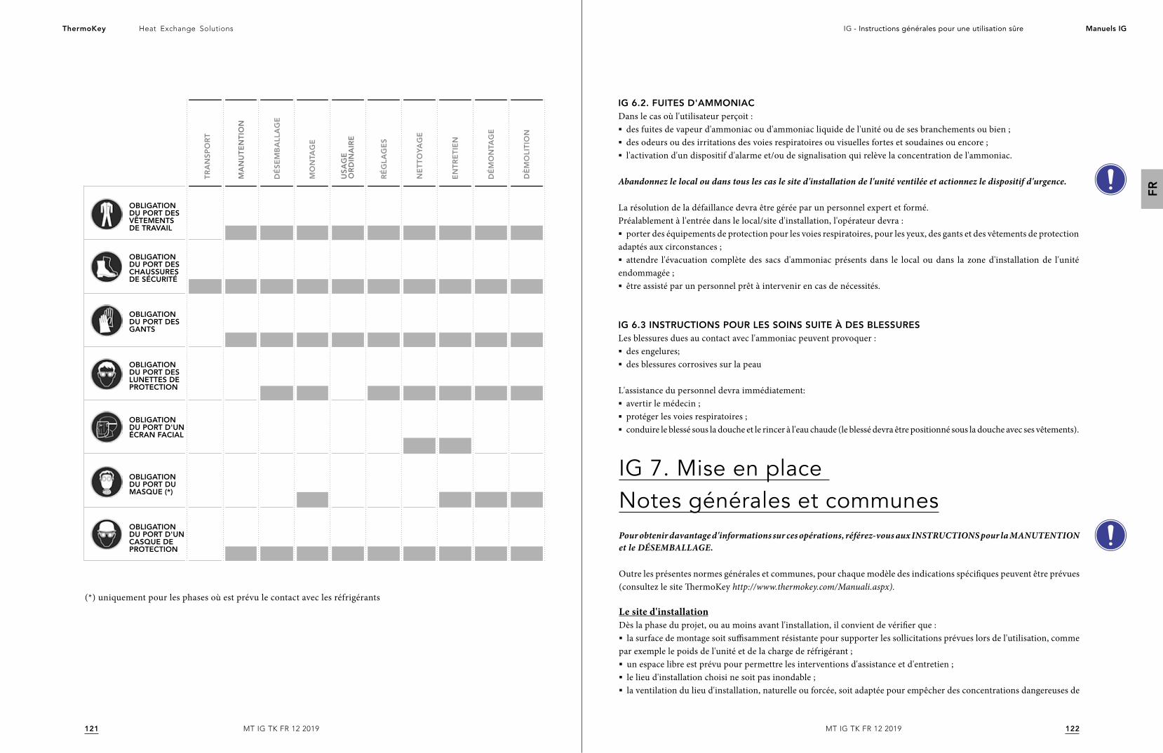
122121
Heat Exchange SolutionsThermoKey IG - Instructions générales pour une utilisation sûre Manuels IG
FR
MT IG TK FR 12 2019MT IG TK FR 12 2019
OBLIGATION DU PORT DES VÊTEMENTS DE TRAVAIL
OBLIGATION DU PORT D'UN ÉCRAN FACIAL
OBLIGATION DU PORT D'UN CASQUE DE PROTECTION
OBLIGATION DU PORT DES GANTS
OBLIGATION DU PORT DES CHAUSSURES DE SÉCURITÉ
OBLIGATION DU PORT DU MASQUE (*)
OBLIGATION DU PORT DES LUNETTES DE PROTECTION
TR
AN
SP
OR
T
MA
NU
TE
NT
ION
DÉ
SE
MB
ALL
AG
E
MO
NTA
GE
RÉ
GLA
GE
S
NE
TT
OYA
GE
EN
TR
ET
IEN
DÉ
MO
NTA
GE
DÈ
MO
LIT
ION
US
AG
E
OR
DIN
AIR
E
(*) uniquement pour les phases où est prévu le contact avec les réfrigérants
IG 6.2. FUITES D'AMMONIACDans le cas où l'utilisateur perçoit :§ des fuites de vapeur d'ammoniac ou d'ammoniac liquide de l'unité ou de ses branchements ou bien ;§ des odeurs ou des irritations des voies respiratoires ou visuelles fortes et soudaines ou encore ;§ l'activation d'un dispositif d'alarme et/ou de signalisation qui relève la concentration de l'ammoniac.
Abandonnez le local ou dans tous les cas le site d'installation de l'unité ventilée et actionnez le dispositif d'urgence.
La résolution de la défaillance devra être gérée par un personnel expert et formé.Préalablement à l'entrée dans le local/site d'installation, l'opérateur devra :§ porter des équipements de protection pour les voies respiratoires, pour les yeux, des gants et des vêtements de protection
adaptés aux circonstances ;§ attendre l'évacuation complète des sacs d'ammoniac présents dans le local ou dans la zone d'installation de l'unité
endommagée ;§ être assisté par un personnel prêt à intervenir en cas de nécessités.
IG 6.3 INSTRUCTIONS POUR LES SOINS SUITE À DES BLESSURESLes blessures dues au contact avec l'ammoniac peuvent provoquer :§ des engelures; § des blessures corrosives sur la peau
L'assistance du personnel devra immédiatement:§ avertir le médecin ;§ protéger les voies respiratoires ;§ conduire le blessé sous la douche et le rincer à l'eau chaude (le blessé devra être positionné sous la douche avec ses vêtements).
IG 7. Mise en place Notes générales et communesPour obtenir davantage d'informations sur ces opérations, référez-vous aux INSTRUCTIONS pour la MANUTENTION et le DÉSEMBALLAGE.
Outre les présentes normes générales et communes, pour chaque modèle des indications spécifiques peuvent être prévues (consultez le site ThermoKey http://www.thermokey.com/Manuali.aspx).
Le site d'installationDès la phase du projet, ou au moins avant l'installation, il convient de vérifier que :§ la surface de montage soit suffisamment résistante pour supporter les sollicitations prévues lors de l'utilisation, comme
par exemple le poids de l'unité et de la charge de réfrigérant ;§ un espace libre est prévu pour permettre les interventions d'assistance et d'entretien ; § le lieu d'installation choisi ne soit pas inondable ;§ la ventilation du lieu d'installation, naturelle ou forcée, soit adaptée pour empêcher des concentrations dangereuses de

124123
Heat Exchange SolutionsThermoKey IG - Instructions générales pour une utilisation sûre Manuels IG
FR
MT IG TK FR 12 2019MT IG TK FR 12 2019
réfrigérants potentiellement explosives ou inflammables ;§ la température locale de l'unité pendant les phases où elle n'est pas en fonctionnement ne doit pas dépasser les 50°C ;§ des supports anti-vibrations et des manchons flexibles peuvent être utilisés sur les tuyaux hydrauliques afin de limiter
au maximum la propagation des vibrations par voie solide ;§ l'impact sonore soit adéquat.
Pour les installations à l'intérieur, il convient en outre de vérifier que le local d'installation doit être conforme aux recommandations de la norme EN 378-3 et aux autres spécifications techniques et légales en vigueur sur le lieu d'installation.
Pour les installations à l'extérieur, vérifiez également que:§ la position de l'unité soit à un niveau supérieur à la hauteur moyenne atteinte par la neige ;§ a surface de montage soit suffisamment résistante pour supporter les sollicitations prévues lors de l'utilisation ordinaire,
comme par exemple le poids de l'unité et de la charge de réfrigérant, et les sollicitations accidentelles, telles que la neige, le vent, etc. en se référant également à la norme EN 1991-5.
Prévoyez l’espace et les moyens nécessaires à l'installation.
Une attention particulière doit être portée à la vérification du risque de corrosion galvanique et, plus particulièrement, il relève de la compétence du concepteur/de l'installateur de prévoir un système de protection.
Prenez en compte (à la charge de l'installateur/du concepteur) de possibles vibrations externes, telles que par exemple la circulation à proximité de routes, les vibrations à proximité des aéroports, etc.
Il est conseillé d’installer des amortisseurs à la base de la structure: consultez le catalogue ou le site Internet www.thermokey.com à la rubrique téléchargement du catalogue. Pour évaluer les sollicitations, il est conseillé de se référer à la norme EN 1991-6.
L'utilisation de systèmes anti-vibrations peut modifier les conditions de résistance aux sollicitations des unités ventilées (le vent et les vibrations propres en particulier).
Pour le dimensionnement des tuyaux, et plus particulièrement pour ceux contenant de l'ammoniac et des réfrigérants du groupe 1, il est recommandé d'appliquer la norme EN 1998-6.
En ce qui concerne le choix du site d'installation, une série de risques possibles, qui peuvent se présenter aussi bien lors de la phase d'installation que lors des phases suivantes d'utilisation ordinaire et de démontage, doivent être pris en compte. Il incombe au concepteur, à l'installateur et/ou à l'utilisateur d'évaluer les risques présents sur le site d'installation. Une liste indicative, mais non exhaustive, est donnée ci-dessous.
La zone à proximité ou le sol en-dessous des unités ventilées peut devenir glissant(e) : signalez le danger de manière appropriée.
Les contreventements et, de manière générale, toutes les structures en saillie de l'unité ventilée peuvent présenter un risque de gêne.
En ce qui concerne les unités ventilées suspendues ou accrochées et les unités ventilées de grandes dimensions, il y a un risque de se cogner la tête en raison de la hauteur des installations.
Pour les installations en hauteur (sur des toits-terrasses, des structures de soutien ou des dispositifs similaires dépassant 2 m de hauteur à partir du plancher) le risque de chute par le haut existe ; celui-ci doit être minimisé grâce à des ÉPC.
L'emploi d'ammoniac et de réfrigérants du groupe 1 peuvent créer un risque d'explosion en raison d'une atmosphère explosive. Durant la phase de conception, toutes les précautions nécessaires doivent être prises pour éviter ce danger.
IG 7.1 ESPACES TECHNIQUES MINIMAUXLes espaces techniques minimaux peuvent être de différents types et, ainsi, il est nécessaire de se référer à toutes les indications spécifiques fournies dans la documentation technique. Dans le cas où elles ne seraient pas présentes, contactez immédiatement ThermoKey pour les obtenir.
IG 7.2 INSPECTION A LA LIVRAISONVérifiez que la confirmation de commande est conforme aux données reportées sur la plaque d'identification et comparez les paramètres électriques à ceux requis. Ne procédez pas à l'installation en cas de différences entre les paramètres.
Si l'unité ventilée présente un défaut au moment du désemballage e/ou de l'installation, signalez-le immédiatement au constructeur et ne n'effectuez pas les phases suivantes avant d'avoir obtenu une autorisation explicite.
IG 7.3 DESEMBALLAGE DE L'UNITELes emballages peuvent être de différents types et, ainsi, il est nécessaire de se référer à toutes les indications spécifiques fournies dans la documentation technique. Dans le cas où elles ne seraient pas présentes, contactez immédiatement ThermoKey pour les obtenir et n'effectuez aucune opération de désemballage.
IG 7.4 MISE EN PLACEIl est interdit de s’arrêter et de circuler dans le rayon d’action de toute machine de levage.
Lorsque présent, il est nécessaire d’ôter le film de protection du carénage après l’installation.
Pour les installations qui prévoient des travaux en hauteur ou exposés à des risques de chute, n'utilisez pas d’échelle mais tenez-vous-en aux normes nationales en vigueur en matière de sécurité pour les « travaux en hauteur ».
Les travaux en hauteur peuvent être effectués uniquement si les conditions météorologiques ne mettent pas en danger la sécurité des travailleurs.
126125
Heat Exchange SolutionsThermoKey IG - Instructions générales pour une utilisation sûre Manuels IG
FR
MT IG TK FR 12 2019MT IG TK FR 12 2019
IG 8. InstallationL'installation est la phase qui survient après la mise en place de l'unité ventilée pendant laquelle s'effectuent les opérations de fixation de celle-ci au support, la mise en place des contreventements et le remontage des pièces éventuellement retirées pour la manutention.
L'installation doit être exécutée conformément aux indications présentes dans le manuel et aux dispositions de la norme EN 378-3.
La fixation mécanique de l'unité ventilée est à la charge de l'installateur. L'unité ventilée est prévue avec des trous de fixation. Si les dimensions des trous étaient insuffisantes, ne les agrandissez pas sans le consentement de ThermoKey.
Les diamètres des trous de fixation sont le résultat de calculs statiques réalisés par le constructeur ; les éléments de fixation doivent tenir compte du diamètre des trous.Les éléments de fixation doivent être dotés de tous les moyens appropriés pour éviter qu'ils ne se relâchent.
Pour le dimensionnement des dispositifs d'ancrage ou de fixation des unités ventilées, utilisez les nomes ETAG de référence et consultez les catalogues techniques sur le site Internet www.thermokey.com à la rubrique téléchargement du catalogue.
Afin d'améliorer la stabilité à la charge du vent des unités installées à l'extérieur, il est possible d'utiliser des contreventements. Le choix et le dimensionnement des contreventements est à la charge de l'installateur.
IG 9. Raccords frigorifiques et hydrauliquesIl est formellement interdit d’adapter la position des collecteurs à la ligne d’alimentation, leur position d’origine ne doit en aucun cas être forcée.§ Lors de la préparation des raccords des conduits IN/OUT, il est obligatoire de vérifier l’indication du flux du réfrigérant
appliquée au niveau des manchons ou des brides. § Il est conseillé d’installer des vannes d’interception en amont pour faciliter les opérations d’entretien. Au cas où
l’installation des vannes susdites présenterait des risques, il revient toujours à l’installateur de prévoir les solutions de circuit appropriées.§ Pour les Condenseurs et les Aéroréfrigérants de type en V équipés de systèmes adiabatiques, en cas de température
ambiante inférieure à 0°C, il est nécessaire de vider l’eau du système d’alimentation afin de prévenir la formation de glace.§ Pour les raccords frigorifiques et hydrauliques, il est obligatoire de respecter les diamètres des raccords prévus. Toute
sorte de modification doit être préalablement convenue avec le service Assistance Clients de ThermoKey, sous peine de déchéance de toute responsabilité relative aux dommages vis-à-vis des personnes, animaux ou biens, aux rendements inférieurs à ceux déclarés et enfin aux Conditions de Garantie.
IG 9.1 RACCORDS HYDRAULIQUESLes raccords hydrauliques doivent être effectués conformément aux normes nationales ou locales. Les tuyaux peuvent être fabriqués en acier, en acier galvanisé ou en PVC. Les tuyaux doivent être dimensionnés très précisément selon le débit nominal du réfrigérant, la pression, les pertes de charge du circuit hydraulique et les températures de service. Tous les raccords hydrauliques doivent être isolés en utilisant un matériau à cellules fermées d'épaisseur appropriée.
IG 9.2. MONTAGE DES TUYAUX§ Fixez correctement tous les tuyaux en évitant les dommages mécaniques en suivant une procédure correcte de montage et
en consultant les indications dans les Spécifications Techniques de la rubrique téléchargement du site www.thermokey.com§ Lors du serrage, soutenez les tuyaux afin de ne pas solliciter les systèmes de fixation de manière inappropriée.§ Si l'installation est réalisée dans des zones de passage du personnel, placez les tuyaux de manière à ce qu'ils ne gênent
pas le passage et assurez-vous que leurs raccords ne s'enlèvent pas facilement.§ Utilisez des dispositifs de fixation adaptés au poids des tuyaux, de manière telle à ce tout le poids ne retombe pas sur
les connexions, en provoquant des ruptures et des décrochages de celles-ci de l'unité.
Dans les unités ventilées qui utilisent de l'ammoniac ou des fluides explosifs ou inflammables, une installation incorrecte des tuyaux comporte un risque de fuites du réfrigérant.
IG 9.3. SOUDAGE§ En ce qui concerne les opérations de raccordement nécessitant le soudage, soudez précisément et attentivement afin de
prévenir les pertes ;§ Évitez la surchauffe lors du soudage (danger de redimensionnement excessif) ;§ Utilisez un gaz de protection lors du soudage (évitez les incrustations excessives) ;§ Les opérations de soudage sur des composants sous pression peuvent provoquer des incendies ou des explosions ; § Effectuez les opérations de soudage uniquement avec l'unité déchargée et non sous pression ;§ Assurez-vous que l'unité ne soit pas sollicitée par des charges ou des vibrations ;§ Pour le soudage des connexions, il est interdit de diriger la flamme vers l’unité et/ou vers tout éventuel équipement
électrique présent.
IG 10. Connexion électriqueLes connexions électriques doivent être réalisées conformément aux instructions de ce manuel, aux schémas électriques fournis dans les Instructions et les Données techniques et aux normes relatives aux installations électriques en vigueur dans le Pays où l’unité est installée.
Il est obligatoire d’effectuer la mise à la terre de l’appareil.
§ Les opérations de connexion électrique doivent être réalisées par un personnel qualifié, possédant les qualifications techniques requises par le Pays où l’unité est installée. § Il est obligatoire de vérifier que la tension de la ligne corresponde à celle indiquée sur la plaque d'identification.§ Le choix et le dimensionnement du câble d'alimentation de l'unité ventilée incombent au concepteur/à l'installateur.§ Lors de la pose du câble d'alimentation, il est recommandé d'utiliser des tubes ou des tuyaux pour protéger mécaniq-
uement le câble. La pose libre à la terre, sans fixation, est absolument déconseillée.§ Il est obligatoire d’utiliser des câbles d’alimentation dont la section minimale et le type sont conformes à la norme EN
60204-1 et, le cas échéant, aux normes techniques en vigueur dans le pays d'installation.§ Les puissances et les absorptions pour le dimensionnement du câble électrique du réseau principal sont disponibles sur
la plaque d'identification et/ou sur les catalogues techniques.§ Il est obligatoire d’équiper l’installation d’alimentation électrique d’un dispositif de protection contre les surcharges de
courant, tel que par exemple un interrupteur magnétothermique, et contre les surtensions.
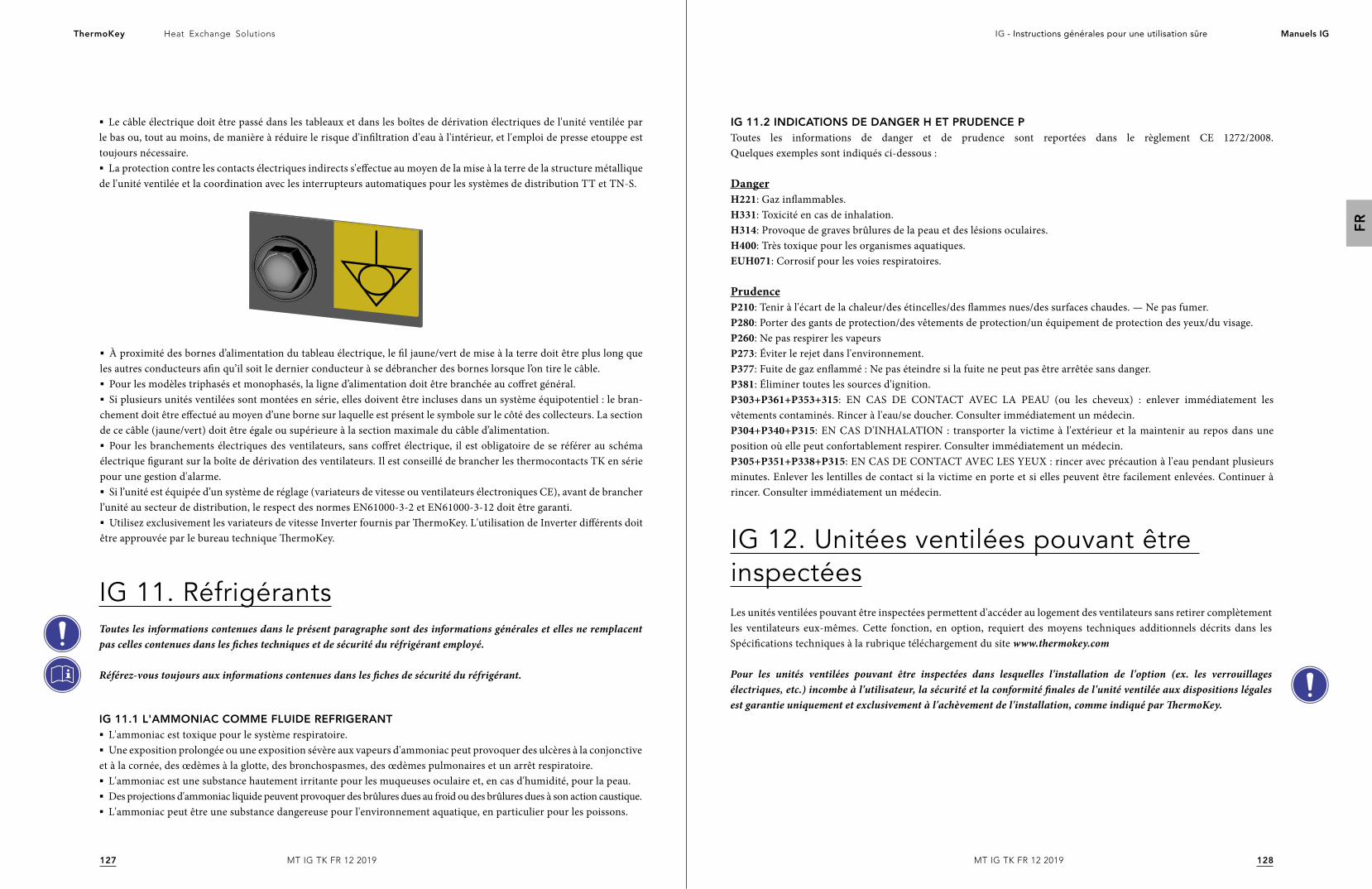
128127
Heat Exchange SolutionsThermoKey IG - Instructions générales pour une utilisation sûre Manuels IG
FR
MT IG TK FR 12 2019MT IG TK FR 12 2019
§ Le câble électrique doit être passé dans les tableaux et dans les boîtes de dérivation électriques de l'unité ventilée par le bas ou, tout au moins, de manière à réduire le risque d'infiltration d'eau à l'intérieur, et l'emploi de presse etouppe est toujours nécessaire.§ La protection contre les contacts électriques indirects s'effectue au moyen de la mise à la terre de la structure métallique
de l'unité ventilée et la coordination avec les interrupteurs automatiques pour les systèmes de distribution TT et TN-S.
IG 11. RéfrigérantsToutes les informations contenues dans le présent paragraphe sont des informations générales et elles ne remplacent pas celles contenues dans les fiches techniques et de sécurité du réfrigérant employé.
Référez-vous toujours aux informations contenues dans les fiches de sécurité du réfrigérant.
IG 11.1 L'AMMONIAC COMME FLUIDE REFRIGERANT§ L'ammoniac est toxique pour le système respiratoire.§ Une exposition prolongée ou une exposition sévère aux vapeurs d'ammoniac peut provoquer des ulcères à la conjonctive
et à la cornée, des œdèmes à la glotte, des bronchospasmes, des œdèmes pulmonaires et un arrêt respiratoire.§ L'ammoniac est une substance hautement irritante pour les muqueuses oculaire et, en cas d'humidité, pour la peau.§ Des projections d'ammoniac liquide peuvent provoquer des brûlures dues au froid ou des brûlures dues à son action caustique.§ L'ammoniac peut être une substance dangereuse pour l'environnement aquatique, en particulier pour les poissons.
IG 12. Unitées ventilées pouvant être inspectéesLes unités ventilées pouvant être inspectées permettent d'accéder au logement des ventilateurs sans retirer complètement les ventilateurs eux-mêmes. Cette fonction, en option, requiert des moyens techniques additionnels décrits dans les Spécifications techniques à la rubrique téléchargement du site www.thermokey.com
Pour les unités ventilées pouvant être inspectées dans lesquelles l'installation de l'option (ex. les verrouillages électriques, etc.) incombe à l'utilisateur, la sécurité et la conformité finales de l'unité ventilée aux dispositions légales est garantie uniquement et exclusivement à l'achèvement de l'installation, comme indiqué par ThermoKey.
IG 11.2 INDICATIONS DE DANGER H ET PRUDENCE PToutes les informations de danger et de prudence sont reportées dans le règlement CE 1272/2008. Quelques exemples sont indiqués ci-dessous :
DangerH221: Gaz inflammables. H331: Toxicité en cas de inhalation. H314: Provoque de graves brûlures de la peau et des lésions oculaires. H400: Très toxique pour les organismes aquatiques. EUH071: Corrosif pour les voies respiratoires.
PrudenceP210: Tenir à l'écart de la chaleur/des étincelles/des flammes nues/des surfaces chaudes. — Ne pas fumer.P280: Porter des gants de protection/des vêtements de protection/un équipement de protection des yeux/du visage. P260: Ne pas respirer les vapeurs P273: Éviter le rejet dans l'environnement.P377: Fuite de gaz enflammé : Ne pas éteindre si la fuite ne peut pas être arrêtée sans danger.P381: Éliminer toutes les sources d'ignition. P303+P361+P353+315: EN CAS DE CONTACT AVEC LA PEAU (ou les cheveux) : enlever immédiatement les vêtements contaminés. Rincer à l'eau/se doucher. Consulter immédiatement un médecin. P304+P340+P315: EN CAS D'INHALATION : transporter la victime à l'extérieur et la maintenir au repos dans une position où elle peut confortablement respirer. Consulter immédiatement un médecin. P305+P351+P338+P315: EN CAS DE CONTACT AVEC LES YEUX : rincer avec précaution à l'eau pendant plusieurs minutes. Enlever les lentilles de contact si la victime en porte et si elles peuvent être facilement enlevées. Continuer à rincer. Consulter immédiatement un médecin.
§ À proximité des bornes d’alimentation du tableau électrique, le fil jaune/vert de mise à la terre doit être plus long que les autres conducteurs afin qu’il soit le dernier conducteur à se débrancher des bornes lorsque l’on tire le câble. § Pour les modèles triphasés et monophasés, la ligne d’alimentation doit être branchée au coffret général.§ Si plusieurs unités ventilées sont montées en série, elles doivent être incluses dans un système équipotentiel : le bran-
chement doit être effectué au moyen d’une borne sur laquelle est présent le symbole sur le côté des collecteurs. La section de ce câble (jaune/vert) doit être égale ou supérieure à la section maximale du câble d’alimentation.§ Pour les branchements électriques des ventilateurs, sans coffret électrique, il est obligatoire de se référer au schéma
électrique figurant sur la boîte de dérivation des ventilateurs. Il est conseillé de brancher les thermocontacts TK en série pour une gestion d'alarme. § Si l’unité est équipée d’un système de réglage (variateurs de vitesse ou ventilateurs électroniques CE), avant de brancher
l’unité au secteur de distribution, le respect des normes EN61000-3-2 et EN61000-3-12 doit être garanti.§ Utilisez exclusivement les variateurs de vitesse Inverter fournis par ThermoKey. L'utilisation de Inverter différents doit
être approuvée par le bureau technique ThermoKey.

Instrukcje ogólne dotyczące bezpiecznego użytkowania
System Zarządzania Jakością ISO 9001System Zarządzania Środowiskowego ISO 14001
System Zarządzania Bezpieczeństwem i Higieną Pracy BS OHSAS 18001
WERSJA ORYGINALNA NINIEJSZEJ INSTRUKCJI JEST W JĘZYKU WŁOSKIM
MT IG TK PL 12 2019P
L
131130
Heat Exchange SolutionsThermoKey IG - Instrukcje ogolne dotyczące bezpiecznego użytkowania Instrukcje IG
PL
MT IG TK PL 12 2019MT IG TK PL 12 2019
NALEŻY UWAŻNIE PRZECZYTAĆ I ZROZUMIEĆ WSZYSTKIE INFORMACJE ZAWARTE W INSTRUKCJI PRZED PROJEKTOWANIEM I KAŻDORAZOWO PRZED WYKONANIEM WSZELKICH CZYNNOŚCI PRZENOSZENIA, ROZPAKOWYWANIA, MONTAŻU, USTAWIANIA I URUCHAMIANIA URZĄDZENIA.
Producent nie ponosi żadnej odpowiedzialności za szkody, w stosunku do osób lub rzeczy, wywołane na skutek nieprzestrzegania wskazówek zawartych w niniejszym dokumencie.
Oryginalna instrukcja powstała w języku włoskim i znajduje się na stronie internetowej: www.thermokey.comTłumaczenie na język angielski jest zgodne z wersją oryginalną i znajduje się na stronie internetowej www.thermokey.comTłumaczenia mogą zawierać błędy – w razie wątpliwości należy zawsze odnieść się do wersji oryginalnej w języku włoskim i do jej tłumaczenia na język angielski.
IDEA INSTRUKCJIKomentarz nr 255 do wytycznych wdrożeniowych, rewizja 2 dyrektywy maszynowej 2006/42/WE zaleca udostępnienie instrukcji w wersji elektronicznej na stronie internetowej, by uniknąć jej zgubienia i ułatwić aktualizację.Ponadto komentarz 275 nakłada wymóg, by istniała zgodność między publikacjami techniczno-handlowymi, takimi jak katalogi oraz instrukcja.Wiele jednostek wentylatorowych ThermoKey jest personalizowanych dla konkretnej instalacji lub danego Klienta.Na podstawie punktów określonych powyżej i w związku z tym, że odbiorcami instrukcji są projektanci instalacji, monterzy oraz użytkownicy, dokumentacja techniczna dotycząca prawidłowego projektowania oraz właściwej eksploatacji jednostki wentylatorowej spełnia ideę wpisaną w szereg dokumentów, które całościowo składają się na INSTRUKCJĘ.
INSTRUKCJE OGÓLNE DOTYCZĄCE BEZPIECZNEGO UŻYTKOWANIA (IG)
INSTRUKCJE DOTYCZĄCE PRZENOSZENIA I ROZPAKOWYWANIA (IM)
INSTRUKCJE I DANE TECHNICZNE (TC)
INSTRUKCJE SZCZEGÓŁOWE OBSŁUGI I KONSERWACJI (IS)
PONIŻEJ PRZEDSTAWIONA JEST STRUKTURA INSTRUKCJI
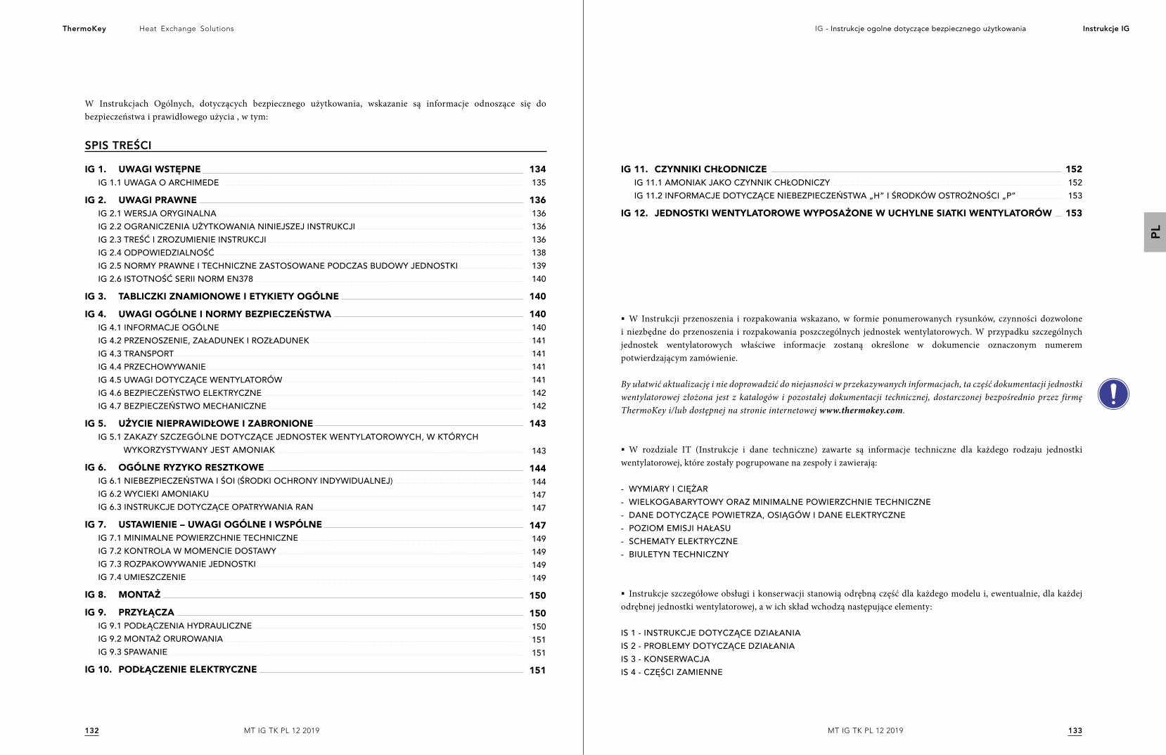
133132
Heat Exchange SolutionsThermoKey IG - Instrukcje ogolne dotyczące bezpiecznego użytkowania Instrukcje IG
PL
MT IG TK PL 12 2019MT IG TK PL 12 2019
W Instrukcjach Ogólnych, dotyczących bezpiecznego użytkowania, wskazanie są informacje odnoszące się do bezpieczeństwa i prawidłowego użycia , w tym:
IG 1. UWAGI WSTĘPNEIG 1.1 UWAGA O ARCHIMEDE
IG 2. UWAGI PRAWNEIG 2.1 WERSJA ORYGINALNAIG 2.2 OGRANICZENIA UŻYTKOWANIA NINIEJSZEJ INSTRUKCJIIG 2.3 TREŚĆ I ZROZUMIENIE INSTRUKCJIIG 2.4 ODPOWIEDZIALNOŚĆIG 2.5 NORMY PRAWNE I TECHNICZNE ZASTOSOWANE PODCZAS BUDOWY JEDNOSTKIIG 2.6 ISTOTNOŚĆ SERII NORM EN378
IG 3. TABLICZKI ZNAMIONOWE I ETYKIETY OGÓLNE
IG 4. UWAGI OGÓLNE I NORMY BEZPIECZEŃSTWAIG 4.1 INFORMACJE OGÓLNEIG 4.2 PRZENOSZENIE, ZAŁADUNEK I ROZŁADUNEKIG 4.3 TRANSPORTIG 4.4 PRZECHOWYWANIEIG 4.5 UWAGI DOTYCZĄCE WENTYLATORÓWIG 4.6 BEZPIECZEŃSTWO ELEKTRYCZNEIG 4.7 BEZPIECZEŃSTWO MECHANICZNE
IG 5. UŻYCIE NIEPRAWIDŁOWE I ZABRONIONEIG 5.1 ZAKAZY SZCZEGÓLNE DOTYCZĄCE JEDNOSTEK WENTYLATOROWYCH, W KTÓRYCH WYKORZYSTYWANY JEST AMONIAK
IG 6. OGÓLNE RYZYKO RESZTKOWEIG 6.1 NIEBEZPIECZEŃSTWA I ŚOI (ŚRODKI OCHRONY INDYWIDUALNEJ)IG 6.2 WYCIEKI AMONIAKUIG 6.3 INSTRUKCJE DOTYCZĄCE OPATRYWANIA RAN
IG 7. USTAWIENIE – UWAGI OGÓLNE I WSPÓLNEIG 7.1 MINIMALNE POWIERZCHNIE TECHNICZNEIG 7.2 KONTROLA W MOMENCIE DOSTAWYIG 7.3 ROZPAKOWYWANIE JEDNOSTKIIG 7.4 UMIESZCZENIE
IG 8. MONTAŻ
IG 9. PRZYŁĄCZAIG 9.1 PODŁĄCZENIA HYDRAULICZNEIG 9.2 MONTAŻ ORUROWANIAIG 9.3 SPAWANIE
IG 10. PODŁĄCZENIE ELEKTRYCZNE
SPIS TREŚCI
134135
136136136136138139140
140
140140141141141141142142
143
143
144144147147
147149149149149
150
150150151151
151
§ W Instrukcji przenoszenia i rozpakowania wskazano, w formie ponumerowanych rysunków, czynności dozwolone i niezbędne do przenoszenia i rozpakowania poszczególnych jednostek wentylatorowych. W przypadku szczególnych jednostek wentylatorowych właściwe informacje zostaną określone w dokumencie oznaczonym numerem potwierdzającym zamówienie.
By ułatwić aktualizację i nie doprowadzić do niejasności w przekazywanych informacjach, ta część dokumentacji jednostki wentylatorowej złożona jest z katalogów i pozostałej dokumentacji technicznej, dostarczonej bezpośrednio przez firmę ThermoKey i/lub dostępnej na stronie internetowej www.thermokey.com.
§ W rozdziale IT (Instrukcje i dane techniczne) zawarte są informacje techniczne dla każdego rodzaju jednostki wentylatorowej, które zostały pogrupowane na zespoły i zawierają:
- WYMIARY I CIĘŻAR- WIELKOGABARYTOWY ORAZ MINIMALNE POWIERZCHNIE TECHNICZNE- DANE DOTYCZĄCE POWIETRZA, OSIĄGÓW I DANE ELEKTRYCZNE- POZIOM EMISJI HAŁASU- SCHEMATY ELEKTRYCZNE- BIULETYN TECHNICZNY
§ Instrukcje szczegółowe obsługi i konserwacji stanowią odrębną część dla każdego modelu i, ewentualnie, dla każdej odrębnej jednostki wentylatorowej, a w ich skład wchodzą następujące elementy:
IS 1 - INSTRUKCJE DOTYCZĄCE DZIAŁANIAIS 2 - PROBLEMY DOTYCZĄCE DZIAŁANIAIS 3 - KONSERWACJAIS 4 - CZĘŚCI ZAMIENNE
IG 11. CZYNNIKI CHŁODNICZEIG 11.1 AMONIAK JAKO CZYNNIK CHŁODNICZYIG 11.2 INFORMACJE DOTYCZĄCE NIEBEZPIECZEŃSTWA „H” I ŚRODKÓW OSTROŻNOŚCI „P”
IG 12. JEDNOSTKI WENTYLATOROWE WYPOSAŻONE W UCHYLNE SIATKI WENTYLATORÓW
152152153
153
135134
Heat Exchange SolutionsThermoKey IG - Instrukcje ogolne dotyczące bezpiecznego użytkowania Instrukcje IG
PL
MT IG TK PL 12 2019MT IG TK PL 12 2019
IG 1. Uwagi wstępneJEDNOSTKA PRZEZNACZONA JEST WYŁĄCZNIE DO UŻYTKU, DO KTÓREGO ZOSTAŁA WYPRODUKOWANA, JAK WSKAZANO W AKAPICIE „UWAGI WSTĘPNE”.
1. Uwagi wstępne są zasadniczą częścią instrukcji i należy je uważnie przeczytać i zrozumieć.
2. Niniejsza instrukcja stanowi część dokumentacji technicznej jednostki wentylatorowej. Niniejsza instrukcja może zostać uzupełniona innymi informacjami oraz może ulec niewielkim zmianom, w zależności od personalizacji lub niestandardowych warunków pracy. Ogółem, instrukcja składa się z części zasadniczej i kilku załączników technicznych. Odniesienia do instrukcji w dalszej części należy rozumieć, o ile nie wskazano inaczej, jako odniesienia do całej dokumentacji technicznej niezbędnej do prawidłowej eksploatacji jednostki wentylatorowej.
3. Należy zachować niniejszą instrukcję przez cały okres użytkowania jednostki wentylatorowej.
4. Należy zwrócić szczególną uwagę na zasady użytkowania znajdujące się w instrukcji, ponieważ ich nieprzestrzeganie może spowodować uszkodzenie jednostki wentylatorowej i/lub szkody dotyczące osób/zwierząt/rzeczy.
5. ThermoKey zastrzega sobie prawo do zmiany niniejszej instrukcji w dowolnym momencie. Rewizje w formie najnowszej wersji są zawsze dostępne na stronie www.thermokey.com. By zweryfikować, czy posiadają Państwo najnowszą wersję, należy sprawdzić indeks rewizji.
6. Dane producenta oraz odniesienie do numeru zamówienia Klienta znajdują się na tabliczce znamionowej jednostki wentylatorowej, która zawiera dane dotyczące samej jednostki oraz numer zamówienia.
Odniesienie do numeru zamówienia jest niezwykle istotne, ponieważ identyfikuje ewentualne personalizacje oraz ograniczenia zastosowania uzgodnione między ThermoKey, czyli producentem, oraz zamawiającym, czyli użytkownikiem.
7. Nieoryginalne części zamienne winny zostać wcześniej zaakceptowane przez ThermoKey.
8. Jednostka wentylatorowa jest zgodna z Wymogami zasadniczymi w zakresie zdrowia i bezpieczeństwa dyrektywy 2006/42/WE, mającymi zastosowanie w standardowych warunkach eksploatacji lub warunkach uzgodnionych z Klientem.
9. Kategorycznie zabrania się wszelkiego zastosowania nieprzewidzianego i nieopisanego w niniejszej instrukcji i/lub które nie zostało uzgodnione między użytkownikiem a ThermoKey przed budową/uruchomieniem jednostki wentylatorowej. Nieprawidłowe użytkowanie jednostki wentylatorowej może powodować niebezpieczne warunki, za których konsekwencje ThermoKey nie ponosi żadnej odpowiedzialności.
10. Jednostka wentylatorowa została przewidziana do eksploatacji wyłącznie z czynnikami chłodniczymi o numerach identyfikacyjnych określonych na tabliczce znamionowej.
11. Zabrania się stosowania czynników chłodniczych innych niż te wyraźnie wskazane.
12. W celu zastosowania amoniaku i czynników chłodniczych z grupy 1 mogą okazać się konieczne dalsze wskazówki i wytyczne stosowania, oprócz tych podanych w niniejszej instrukcji, które jednak w każdym przypadku podane są w instrukcji jednostki wentylatorowej.
13. Zabrania się stosowania substancji i płynów, które mogą uszkodzić, zaburzyć bezpieczeństwo lub zmniejszyć osiągi jednostki wentylatorowej.
14. Wszystkie dane techniczne jednostki wentylatorowej oraz wszystkie ograniczenia eksploatacji, jak również minimalne właściwości, jakie musi posiadać miejsce instalacji, znajdują się w katalogach technicznych.
15. Jeżeli konieczne okażą się modyfikacje lub zmiany jednostki wentylatorowej po jej wyprodukowaniu, lecz przed jej uruchomieniem, bądź jeśli warunki operacyjne miejsca instalacji są niezgodne z warunkami przewidzianymi wcześniej, czy też każdorazowo, gdy pojawiają się różnice między wartościami przewidzianymi przed produkcją a stanem faktycznym miejsca instalacji, należy niezwłocznie zwrócić się do firmy ThermoKey, koniecznie przed podjęciem jakichkolwiek czynności mających na celu modyfikacje.
16. Projektant, monter i/lub użytkownik winien przestrzegać norm i przepisów lokalnych dotyczących instalacji, eksploatacji i utylizacji jednostki wentylatorowej.
17. Wykwalifikowany personel, jeśli nie zaznaczono inaczej, oznacza zawsze w niniejszej instrukcji osobę, która uzyskała odpowiednie informacje lub jest nadzorowana przez osobę, która przeszła odpowiednie szkolenie, posiada wiedzę i doświadczenie, które umożliwiają wykonanie robót zgodnie z dobrą praktyką oraz pozwalają na ocenę ryzyka i unikanie zagrożeń, które mogą z nich wyniknąć
18. Warunki gwarancji znajdują się w uzgodnieniach podjętych na etapie zamówienia.
19. Zabrania się kopiowania całości lub części niniejszej instrukcji bez pisemnej zgody producenta. Aktualne wersje niniejszej instrukcji znajdują się na stronie www.thermokey.com
IG 1.1. UWAGA O ARCHIMEDE 1. Wartość napięcia podana w odniesieniu do danych nominalnych otrzymanych od dostawcy: rzeczywisty pobór mocy wentylatorów może się różnić w miarę zmian temperatury otoczenia oraz wahań napięcia.
2. Urządzenie może nie nadawać się do atmosfery bardzo agresywnej. W przypadku zastosowań specjalnych prosimy o kontakt z ThermoKey. Jeśli wybrano specjalny materiał lamel (miedź, powłoka), wszystkie inne materiały urządzenia pozostają standardowe (szczegółowe informacje znajdują się w opisie technicznym urządzenia).
3. Wymiary i waga nie uwzględniają wszystkich możliwych opcji. Ogólne wymiary w arkuszu danych odnoszą się do urządzeń bez elementów sterujących / paneli elektrycznych (szczegółowe informacje znajdują się w instrukcji skrzynki elektrycznej). W przypadku jednostek z poziomym przepływem powietrza, standardowo przyłącza znajdują się po lewej stronie patrząc od strony lamel.
4. Jakikolwiek hałas spowodowany przez układy sterowania, układ adiabatyczny itp. nie jest uwzględniany w deklaracji hałasu emitowanego przez wentylator. Rzeczywiste wartości mogą również podlegać zmianom w zależności od warunków instalacji.
5. Instrukcja składa się z 4 części; IG = Ogólne instrukcje bezpiecznego użytkowania, IM = Instrukcje dotyczące obsługi i rozpakowywania, TC = Instrukcje i dane techniczne, IS = Szczegółowe instrukcje użytkowania i konserwacji. Jeśli nie jest to wyraźnie wymagane na etapie zamówienia przed zakupem, instrukcje dotyczące TC i IS muszą zostać pobrane przez użytkownika z witryny www.thermokey.com, ponieważ nie zostaną dostarczone w formie papierowej.Instalator jest zobowiązany do przestrzegania powyższych instrukcji oraz instrukcji dotyczących głównych komponentów elektrycznych (np. wentylatorów, pomp, regulatorów).
6. Urządzenie jest dostarczane z wentylatorami spełniającymi wymagania dyrektywy ERP 2009/125/EC.
137136
Heat Exchange SolutionsThermoKey IG - Instrukcje ogolne dotyczące bezpiecznego użytkowania Instrukcje IG
PL
MT IG TK PL 12 2019MT IG TK PL 12 2019
IG 2. Uwagi prawneIG 2.1. WERSJA ORYGINALNAWersja oryginalna niniejszej instrukcji jest w języku włoskim i dołączona jest do jej każdego oficjalnego tłumaczenia. Tłumaczenia nieautoryzowane przez producenta nie są uznawane za ważne.
Korzystanie z nieautoryzowanych kopii i/lub tłumaczeń niniejszej instrukcji i/lub używanie tłumaczeń pozbawionych wersji oryginalnej w języku włoskim zwalnia ThermoKey z jakiejkolwiek odpowiedzialności w razie wypadku.
IG 2.2. OGRANICZENIA UŻYTKOWANIA NINIEJSZEJ INSTRUKCJINiniejsza instrukcja obsługi i konserwacji została przygotowana dla jednostek wentylatorowych przeznaczonych na rynek Wspólnoty Europejskiej, które wyróżniają się oznaczeniem CE.
Niniejsza instrukcja obsługi i konserwacji nie obejmuje wprowadzenia na rynek i/lub zastosowania w krajach, które nie są członkami Unii Europejskiej.
IG 2.3. TREŚĆ I ZROZUMIENIE INSTRUKCJIJeśli projektant, monter i/lub użytkownik (ogółem rzecz ujmując – operatorzy) nie znajdą potrzebnych informacji technicznych w niniejszej instrukcji dotyczących instalacji, eksploatacji, konserwacji i/lub utylizacji jednostki lub będą mieli wątpliwości dotyczące prawidłowego sposobu montażu, eksploatacji, konserwacji i/lub utylizacji, są proszeni o skontaktowanie się z firmą ThermoKey. Niniejsza instrukcja obsługi i konserwacji została opracowana w sposób możliwie najpełniejszy i najbardziej zrozumiały w odniesieniu do przygotowania i kompetencji użytkowników.Niezrozumienie treści niniejszej instrukcji lub niepełne zrozumienie informacji w niej zawartych stanowi wystarczający powód do natychmiastowego przerwania każdego etapu projektowania, montażu, obsługi, konserwacji i/lub utylizacji jednostki.
Jeśli operatorzy będą kontynuować pracę, nie rozumiejąc lub nie w pełni rozumiejąc treść niniejszej instrukcji obsługi i konserwacji i/lub nie posiadając pełnej wiedzy ani niezbędnych informacji potrzebnych do wykonywania prac, wówczas firma ThermoKey jest zwolniona z odpowiedzialności i nie odpowiada za wszelkie tego konsekwencje.
7. Zgodnie z EN 13487 deklarowany poziom ciśnienia akustycznego dla tego urządzenia został obliczony w warunkach pola swobodnego nad płaszczyzną odbijającą o równoległościanowej powierzchni. W odniesieniu do ISO 3744, gdy różnica pomiaru urządzenia w fazie włączania i wyłączania wynosi <= 6 dB (A), pomiar dźwięku nie osiąga dokładności wymaganej przez dyrektywę. Wartości szumów tła niższe niż 30 dB (A) są typowe dla środowisk wewnętrznych i cichych. Deklaracja ciśnienia akustycznego urządzenia, podana na kartach danych ThermoKey, uznaje hałas tła za nieistotny.
8. S x x x x : numer seryjny kombinacji standardowych opcji dostępnych w Archimede (wg sekcji AKCESORIA) oraz specjalnych, na życzenie. Kod znajduje się na potwierdzeniu zamówienia (jako część kodu urządzenia) oraz na tabliczce znamionowej. Uwaga: Dla każdego zakresu dostępne opcje są wymienione w katalogu. Rejestr kombinacji opcji związanych z kodem S x x x x jest dostępny na życzenie.
9. Dostępność wersji standardowej podawana jest jako “ex-works”. W przypadku wykonań (i ilości) niestandardowych prosimy o kontakt z Przedstawicielem Handlowym ThermoKey.
10. Urządzenie standardowe nie jest wykonaniem ze spadem grawitacyjnym: wybór cieczy (woda/glikol) ściśle zależy od temperatury zamarzania i faktycznym okresem eksploatacji urządzenia. Odnośnie wersji ze spadem grawitacyjnym prosimy o kontakt z Przedstawicielem Handlowym ThermoKey.
11. Deklarowany zasięg strugi oznacza odległość od wentylatora dla której prędkość powietrza wynosi 0.25 m/s. Zasięg strugi odnosi się tylko dla domyślnego przepływu powietrza: w przypadku modeli przyściennych i komercyjnych z wentylatrem połączonym w trójkąt lub jednofazowym, w modelach podsufitowych z połączeniem zdefiniowanym przez serię.
12. Wymiarowanie odbywa się poprzez symulację programu doborowego, który nie uwzględnia wpływu warunków instalacji.
13. W celu dobrania maksymalnego ciśnienia roboczego uwzględnia się ciśnienie związane z temperaturą skraplania (tj. punktem średnim)
14. W przypadku urządzeń mikrokanałowych należy przestrzegać zaleceń ze strony internetowej ThermoKey (wskazania dla użytkowania bloków TK Micro).
15. Grupa cieczy wg dyrektywy 2014/68 / CE.
16. Dane na tabliczce znamionowej wentylatora nie uwzględniają wartości skrajnych.
17. Podane parametry dotyczą aplikacji HVAC gdzie zapewniony jest swobodny pzepływ powietrza po stronie wymienników oraz wentylatorów (należy unikać recyrkulacji oraz przeszkód ograniczających przepływ powietrza) i z jednakową temperaturą wlotu na blok wymiennika (należy unikać sytuacji, w których sąsiednieurządzenia powodują zmiany temperatury na wlocie jednostki). Dla innych zastowań (n.p. przemysł, elektrownie, itp.) prosimy o kontakt z ThermoKey.
18. ThermoKey zastrzega sobie prawo do zmiany danych technicznych, rysunków i cen w programie Archimede w dowolnym momencie i bez uprzedzania. Prosimy o używanie aktualnej wersji programu.
19. Program Archimede opiera się na najnowszych bibliotekach Refprop's odnośnie olejów, czynników i mieszanin. Aktualizacja może wykazywać parametry odmienne od pochodzących ze starszych edycji programu Archimede.
20. Należy zwrócić uwagę, aby wymiary i masa urządzenia wyposażonego w system EPS, wskazane w karcie technicznej, odnosiły się do modelu bez części elektrycznej i zamontowanych paneli wyparnych, w celu zmiany możliwych kombinacji opcji odsyłamy do następujących wskazówek!Należy wziąć pod uwagę, że moduły wyparne zamontowane z boku modelu wystają łącznie o 440 mm na szerokość modelu, podczas gdy nie wpływają na długość i wysokość modelu, ponadto dodatkowo wystają rury odprowadzające zamontowane na urządzeniach 320 mm łacznie na szerokości modelu. Należy wziąć pod uwagę, że panele sterowania i orurowanie połączeń wystają w zależności od wybranych kombinacji 400 mm od krańców modelu.Należy przyjąć 60 kg dla każdego modułu (na wentylator) wagi operacyjnej modułów wyparnych zamontowanych na mokrych panelach. Należy zwrócić uwagę, że w przypadku nieoptymalnej konserwacji odprowadzających tac ociekowych lub linii wyładowczej, trzeba rozważyć ewentualne zatrzymywanie wody w tacy i w rurach rozładowujących systemu EPS około 30 kilogramów na moduł (na wentylator). Przyjmuje się wstępnie zamontowany przewód połączeniowy systemu EPS do sieci wodociągowej na modelu około 25 kilogramów na jednostkę. Przyjmuje się wagę możliwego wstępnie zamontowanego panelu sterowania elektrycznego systemu EPS na modelu około 35 kg na jednostkę.
139138
Heat Exchange SolutionsThermoKey IG - Instrukcje ogolne dotyczące bezpiecznego użytkowania Instrukcje IG
PL
MT IG TK PL 12 2019MT IG TK PL 12 2019
ThermoKey uważa za zaniedbanie brak zgłoszenia jakichkolwiek błędów, przeoczeń, błędów drukarskich, niezgodności itp. występujących w niniejszej instrukcji, w zakresie instrukcji i wskazówek technicznych; projektant, monter i użytkownik (konserwatorzy) muszą niezwłocznie zgłosić ThermoKey sytuacje, które mogą skutkować zmniejszeniem bezpieczeństwa osób, rzeczy i środowiska oraz muszą działać w sposób kompetentny i profesjonalny, wykazując się pracą zespołową i konieczną starannością.
Jakiekolwiek zachowanie niedbałe, nieostrożne lub wykazujące brak kompetencji technicznych i zawodowych zwalnia producenta z odpowiedzialności za wszelkie konsekwencje.
IG 2.4. ODPOWIEDZIALNOŚĆOdpowiedzialność producentaProducent ponosi odpowiedzialność za projektowanie, budowę, odbiór i pakowanie jednostki wentylatorowej w celu jej wprowadzenia na rynek Unii Europejskiej. Producent zapewnia, że jednostka wentylatorowa została zaprojektowana, zbudowana, odebrana i opakowana w sposób spełniający niezbędne wymogi określone w dyrektywach unijnych oraz że została wykonana odpowiednia ocena zgodności w tym zakresie.Producent nie odpowiada za etapy usuwania opakowania, instalacji, uruchomienia, konserwacji, demontażu i utylizacji. W niniejszej instrukcji producent zawarł możliwie najwięcej informacji potrzebnych na opisanych etapach działania jednostki wentylatorowej.Wszystkie części zostały zaprojektowane, wykonane i odebrane w sposób umożliwiający zniesienie obciążeń, które można przewidzieć w racjonalny sposób w zakresie użytkowania przewidzianego i tego, które można przewidzieć w sposób racjonalny: nie można zapewnić gwarancji bezpieczeństwa/działania, jeśli jednostki używane są w warunkach obsługi, które nie zostały przewidziane przez ThermoKey, a zatem w warunkach zabronionych.
Montaż, obsługa, konserwacja i/lub utylizacja urządzenia w warunkach zabronionych, nieprzewidzianych i/lub w jakikolwiek sposób innych od przewidzianych przez ThermoKey zwalniają przedsiębiorstwo ThermoKey z wszelkich konsekwencji i odpowiedzialności.
Odpowiedzialność projektanta i monteraMonter i/lub projektant mają obowiązek ocenić ryzyko i przygotować środki i systemy awaryjne, alarmowe, sygnalizację i ochronę, jak również muszą przygotować kompleksowe instrukcje dotyczące instalacji /systemu chłodzenia, których częścią jest jednostka wentylatorowa, jak opisano w normie EN 378-4.Ponadto zadaniem projektanta i/lub montera jest określenie najlepszych i najbezpieczniejszych środków i sposobów przenoszenia i, ewentualnie, przechowywania jednostki poza siedzibą i/lub magazynami producenta. W szczególności zakres odpowiedzialności projektanta i/lub montera obejmuje sprawdzenie wytycznych dostarczonych przez producenta, ich przestrzeganie i pilnowanie ich przestrzegania na etapach przenoszenia, transportu i przechowywania.
Nieprawidłowa ocena ryzyka przez projektanta i/lub montera bądź niewłaściwy wybór środków i systemów awaryjnych, alarmowych, sygnalizacji i ochrony zwalniają firmę ThermoKey z wszelkich konsekwencji i odpowiedzialności.
Projektant jest osobą, która prowadzi prace na etapie projektowania instalacji /systemu chłodzenia, w których jednostka wentylatorowa jest montowana. Jego odpowiedzialnością jest zarówno zakres osiągów, jak i bezpieczeństwo. Projektant ponosi odpowiedzialność za wybór komponentów, które będą najodpowiedniejsze dla projektowanej instalacji w zakresie ograniczeń użytkowania narzuconych przez producenta. Przygotowanie projektanta i jego kompetencje muszą być wystarczające, by zrozumiał on treść niniejszej instrukcji obsługi i konserwacji oraz wszystkich innych dokumentów technicznych i handlowych dotyczących jednostki, oraz muszą być wystarczające, by poprosić producenta o ewentualne
dodatkowe wyjaśnienia w zakresie realizacji instalacji/systemu działającego, bezpiecznego i zgodnego z zasadami sztuki budowlanej. W szczególności projektant musi być w stanie określić warunki pracy jednostki, które można przewidzieć w racjonalny sposób (warunki środowiska, mocowania, ładunku i obciążeń, podłączeń do instalacji elektrycznej, płynów, hydraulicznej itp.), i sprawdzić, czy jednostka jest odpowiednia do pracy w takich warunkach.
Błędne określenie warunków pracy jednostki wentylatorowej przez projektanta zwalnia ThermoKey z wszelkiej odpowiedzialności i konsekwencji.
Jeśli projekt jest podzielony na części, koordynator procesu projektowania, kimkolwiek jest, będzie uznawany za projektanta.Monter jest osobą, która pracuje przy uruchomieniu i wykonaniu instalacji zgodnie z wytycznymi projektowymi, specyfikacjami komponentów określonymi przez ich producentów oraz zgodnie z zasadami sztuki budowlanej. Przygotowanie montera i jego kompetencje muszą być wystarczające, by zrozumiał on treść niniejszej instrukcji obsługi i konserwacji oraz wszystkich innych dokumentów technicznych i handlowych dotyczących jednostki, oraz muszą być wystarczające, by poprosić producenta o ewentualne dodatkowe wyjaśnienia w zakresie realizacji instalacji/systemu działającego, bezpiecznego i zgodnego z zasadami sztuki budowlanej.
Personel, który podejmuje prace na poszczególnych etapach montażu i uruchomienia jednostki, musi być kompetentny i przeszkolony. By zapewnić przydatność, minimalny poziom kompetencji, jaki należy zagwarantować, został wskazany w normie EN 13313.
Jeśli montaż jest podzielony na części, koordynator procesu montażu, kimkolwiek jest, będzie uznawany za montera.
Odpowiedzialność osoby kierującej instalacją/systemem chłodzeniaOsoba kierująca zajmuje się eksploatacją instalacji, a zatem jednostki będącej przedmiotem niniejszej instrukcji obsługi i konserwacji. Osoba kierująca jest odpowiedzialna za konserwację jednostki.
Personel, który podejmuje prace na poszczególnych etapach montażu i uruchomienia jednostki, musi być kompetentny i przeszkolony. By zapewnić przydatność, minimalny poziom kompetencji, jaki należy zagwarantować, został wskazany w normie EN 13313.
Kierujący ma obowiązek zatrudnić wyłącznie personel kompetentny i przeszkolony, posiadający niezbędne środki ochrony indywidualnej podczas kontroli, konserwacji, naprawy, sytuacji awaryjnych i utylizacji jednostki.
Przypominamy, że projektowane instalacji/systemu chłodzenia nie jest obowiązkiem firmy ThermoKey, zatem przedsiębiorstwo jest zwolnione z wszelkich konsekwencji i/lub odpowiedzialności wynikającej z błędnego projektowania/instalacji.
Przypominamy, że jednostki mogą ulec zmianom technicznym i/lub aktualizacjom wprowadzonym przez producenta, zatem to osoba kierująca ponosi odpowiedzialność za kompatybilność instalacji/systemu z nową wersją jednostki.
IG 2.5 NORMY PRAWNE I TECHNICZNE ZASTOSOWANE PODCZAS BUDOWY JEDNOSTKIW zakresie norm zastosowanych przez producenta podczas budowy jednostki należy zawsze odnosić się do Oświadczenia firmy ThermoKey przesyłanego wraz z jednostką.

141140
Heat Exchange SolutionsThermoKey IG - Instrukcje ogolne dotyczące bezpiecznego użytkowania Instrukcje IG
PL
MT IG TK PL 12 2019MT IG TK PL 12 2019
IG 2.6. ISTOTNOŚĆ SERII NORM EN 378Normy techniczne EN 378 stanowią serię czterech norm technicznych (EN 378-1, EN 378-2, EN 378-3 i EN 378-4), przedstawiających zasadnicze wytyczne w zakresie projektowana, montażu, obsługi, konserwacji i utylizacji instalacji i odnośnej aparatury chłodzącej.Normy tej serii ukierunkowane są na dostarczenie pełnej gamy wytycznych w zakresie bezpieczeństwa, które muszą zostać uwzględnione przez projektantów, monterów, kierujących i konserwatorów instalacji.ThermoKey uznaje przestrzeganie norm z serii EN 378 za zasadnicze dla bezpieczeństwa osób, rzeczy i środowiska podczas eksploatacji jednostki będącej przedmiotem niniejszej instrukcji obsługi instalacji/systemu chłodzenia.Nieprzestrzeganie wytycznych zawartych w normach może zasadniczo, lecz niewyczerpująco, nieść za sobą następujące skutki:§ niebezpieczeństwo wycieku lub emisji czynnika chłodniczego oraz, w konsekwencji, pożar lub wybuch i/lub szkodliwe
skutki dla zdrowia osób, uszkodzenia rzeczy czy szkody dla środowiska§ ryzyko wypadków na poszczególnych etapach montażu, użytkowania, konserwacji i utylizacji, których ofiarami mogą
być osoby biorące udział w pracach podczas tych etapów.
IG 3. Tabliczki znamionowe i etykiety ogólneUżytkownik winien zagwarantować, aby tabliczki znamionowe umieszczone przez producenta na jednostce utrzymywane były w dobrym stanie, czytelne i dobrze przymocowane. Jeśli tabliczki i etykiety są zużyte, nieczytelne lub niezrozumiałe z jakiegokolwiek innego powodu, należy je wymienić.
IG 4. Uwagi ogólne i normy bezpieczeństwaIG 4.1. INFORMACJE OGÓLNE1. Jednostka wentylatorowa przewidziana jest do użytku automatycznego bez nadzoru.
2. Projektant i/lub monter muszą uwzględnić występowanie uderzeń hydraulicznych.
3. System mocowania jednostki wentylatorowej zapewniany jest przez użytkownika, który musi upewnić się, że został on zaprojektowany zgodnie z wytycznymi ETAG obowiązującymi dla danego rodzaju systemu nośnego.
4. Użytkownicy jednostek wentylatorowych, w których wykorzystywane są niebezpieczne czynniki, muszą przestrzegać uważnie wytycznych określonych w kartach charakterystyki czynnika
5. Wentylacja pomieszczenia, w którym montowane są jednostki wentylatorowe wykorzystujące czynniki potencjalnie wybuchowe lub łatwopalne, ma kluczowe znaczenie: projektant, monter i/lub użytkownik są za nią odpowiedzialni.
6. Wentylatory zostały zaprojektowane do pracy ciągłej S1 (działanie ciągłe przy stałym obciążeniu). Jeśli wentylatory są używane z systemem regulacji ON/OFF, kontrola nie może uwzględniać zbyt częstych przełączeń (patrz karta techniczna wentylatora).
7. Oprócz ostrzeżeń przedstawionych w tym rozdziale dla każdego modelu mogą obowiązywać wytyczne szczególne (patrz strona ThermoKey http://www.thermokey.com/Manuali.aspx).
IG 4.2. PRZENOSZENIE, ZAŁADUNEK I ROZŁADUNEK1. Przenoszenie i przesuwanie podczas załadunku i rozładunku muszą być wykonywane przez wykwalifikowany personel zaopatrzony w odpowiednie narzędzia, zgodnie z wytycznymi producenta.
2. W szczególności osoby zajmujące się przenoszeniem jednostki muszą:- upewnić się, że urządzenie podnoszące, które mają do dyspozycji, jest dostosowane do ciężaru jednostki z zachowaniem odpowiedniego marginesu bezpieczeństwa,- upewnić się, że w promieniu działania używanego urządzenia na etapie rozładunku oraz w strefie wykonywanych prac nie przebywają ludzie,- upewnić się, że jednostka została przyczepiona odpowiednimi hakami wyłącznie w punktach wyznaczonych przez producenta.
Nieprzestrzeganie jednego lub kilku punktów wskazanych powyżej, i ogólne zachowanie, które może spowodować niebezpieczeństwo dla zdrowia i życia osób podczas przenoszenia jednostki, zwalnia producenta z wszelkich możliwych konsekwencji i odpowiedzialności
Nieprzestrzeganie wytycznych opisanych powyżej może skutkować następującymi obrażeniami:- zgniecenie- odcięcie kończyn
Ponadto może skutkować uszkodzeniami jednostki, wpływając negatywnie na jej prawidłowe działanie.
IG 4.3. TRANSPORTW przypadku transportu drogą morską lub lądową drogami o szczególnych warunkach nawierzchni (wyboje) należy koniecznie usunąć z jednostek wentylatorowych wszystkie części, które mogą ulec uszkodzeniu i spowodować usterkę lub nieprawidłowe działanie w przyszłości. Można również zapewnić specjalne opakowanie.
Demontaż i ponowny montaż musi zostać wykonany wyłącznie po tym, jak firma ThermoKey wyda pozwolenie i wyłącznie po uzyskaniu od firmy ThermoKey bezpośrednich i precyzyjnych wytycznych. Nieprzestrzeganie tych wytycznych zwalnia firmę ThermoKey z wszelkiej odpowiedzialności w przyszłości
IG 4.4. PRZECHOWYWANIEJeśli urządzenie musi być przechowywane przed montażem (przez jeden lub kilka miesięcy), dobrze jest przestrzegać następujących środków ostrożności:§ pozostawić jednostkę wentylatorową w oryginalnym opakowaniu aż do momentu montażu lub przełożyć urządzenie
do innego opakowania odpowiadającego opakowaniu oryginalnemu stopniem zabezpieczenia przed czynnikami atmosferycznymi, pyłem, insektami lub gryzoniami,§ przechowywać pod przykryciem w temperaturze między +15°C a +25ºC i przy wilgotności od 50% do 70%,§ upewnić się, że jednostka nie jest narażona na płyny bądź opary powodujące korozję,§ jednostki nie mogą być składowane jedna na drugiej podczas przechowywania i transportu, o ile nie zostało to wyraźnie wskazane.
Nieprzestrzeganie wytycznych dotyczących przechowywania zwalnia firmę ThermoKey z wszelkiej odpowiedzialności za uszkodzenia powstałe w wyniku niewłaściwego przechowywania jednostki wentylatorowej.
IG 4.5 UWAGI DOTYCZĄCE WENTYLATORÓWJeśli jednostka montowana jest na zewnątrz, lecz nie jest od razu uruchamiana, zaleca się wprawienie w ruch wentylatora/-ów przynajmniej raz na tydzień na 4-6 godzin, by nie dopuścić do uszkodzenia silników elektrycznych.
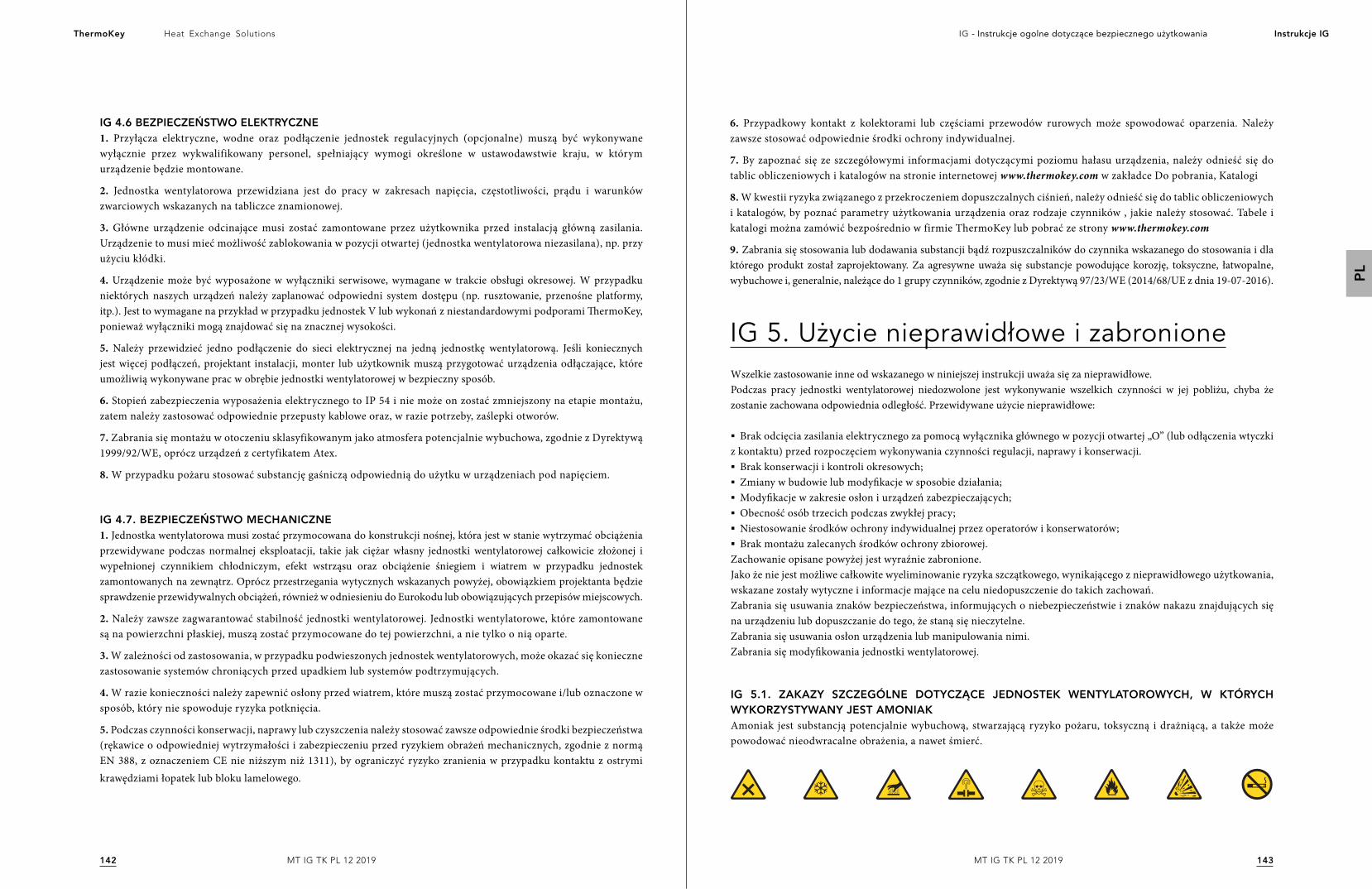
143142
Heat Exchange SolutionsThermoKey IG - Instrukcje ogolne dotyczące bezpiecznego użytkowania Instrukcje IG
PL
MT IG TK PL 12 2019MT IG TK PL 12 2019
IG 4.6 BEZPIECZEŃSTWO ELEKTRYCZNE1. Przyłącza elektryczne, wodne oraz podłączenie jednostek regulacyjnych (opcjonalne) muszą być wykonywane wyłącznie przez wykwalifikowany personel, spełniający wymogi określone w ustawodawstwie kraju, w którym urządzenie będzie montowane.
2. Jednostka wentylatorowa przewidziana jest do pracy w zakresach napięcia, częstotliwości, prądu i warunków zwarciowych wskazanych na tabliczce znamionowej.
3. Główne urządzenie odcinające musi zostać zamontowane przez użytkownika przed instalacją główną zasilania. Urządzenie to musi mieć możliwość zablokowania w pozycji otwartej (jednostka wentylatorowa niezasilana), np. przy użyciu kłódki.
4. Urządzenie może być wyposażone w wyłączniki serwisowe, wymagane w trakcie obsługi okresowej. W przypadku niektórych naszych urządzeń należy zaplanować odpowiedni system dostępu (np. rusztowanie, przenośne platformy, itp.). Jest to wymagane na przykład w przypadku jednostek V lub wykonań z niestandardowymi podporami ThermoKey, ponieważ wyłączniki mogą znajdować się na znacznej wysokości.
5. Należy przewidzieć jedno podłączenie do sieci elektrycznej na jedną jednostkę wentylatorową. Jeśli koniecznych jest więcej podłączeń, projektant instalacji, monter lub użytkownik muszą przygotować urządzenia odłączające, które umożliwią wykonywane prac w obrębie jednostki wentylatorowej w bezpieczny sposób.
6. Stopień zabezpieczenia wyposażenia elektrycznego to IP 54 i nie może on zostać zmniejszony na etapie montażu, zatem należy zastosować odpowiednie przepusty kablowe oraz, w razie potrzeby, zaślepki otworów.
7. Zabrania się montażu w otoczeniu sklasyfikowanym jako atmosfera potencjalnie wybuchowa, zgodnie z Dyrektywą 1999/92/WE, oprócz urządzeń z certyfikatem Atex.
8. W przypadku pożaru stosować substancję gaśniczą odpowiednią do użytku w urządzeniach pod napięciem.
IG 4.7. BEZPIECZEŃSTWO MECHANICZNE1. Jednostka wentylatorowa musi zostać przymocowana do konstrukcji nośnej, która jest w stanie wytrzymać obciążenia przewidywane podczas normalnej eksploatacji, takie jak ciężar własny jednostki wentylatorowej całkowicie złożonej i wypełnionej czynnikiem chłodniczym, efekt wstrząsu oraz obciążenie śniegiem i wiatrem w przypadku jednostek zamontowanych na zewnątrz. Oprócz przestrzegania wytycznych wskazanych powyżej, obowiązkiem projektanta będzie sprawdzenie przewidywalnych obciążeń, również w odniesieniu do Eurokodu lub obowiązujących przepisów miejscowych.
2. Należy zawsze zagwarantować stabilność jednostki wentylatorowej. Jednostki wentylatorowe, które zamontowane są na powierzchni płaskiej, muszą zostać przymocowane do tej powierzchni, a nie tylko o nią oparte.
3. W zależności od zastosowania, w przypadku podwieszonych jednostek wentylatorowych, może okazać się konieczne zastosowanie systemów chroniących przed upadkiem lub systemów podtrzymujących.
4. W razie konieczności należy zapewnić osłony przed wiatrem, które muszą zostać przymocowane i/lub oznaczone w sposób, który nie spowoduje ryzyka potknięcia.
5. Podczas czynności konserwacji, naprawy lub czyszczenia należy stosować zawsze odpowiednie środki bezpieczeństwa (rękawice o odpowiedniej wytrzymałości i zabezpieczeniu przed ryzykiem obrażeń mechanicznych, zgodnie z normą EN 388, z oznaczeniem CE nie niższym niż 1311), by ograniczyć ryzyko zranienia w przypadku kontaktu z ostrymi krawędziami łopatek lub bloku lamelowego.
IG 5. Użycie nieprawidłowe i zabronioneWszelkie zastosowanie inne od wskazanego w niniejszej instrukcji uważa się za nieprawidłowe.Podczas pracy jednostki wentylatorowej niedozwolone jest wykonywanie wszelkich czynności w jej pobliżu, chyba że zostanie zachowana odpowiednia odległość. Przewidywane użycie nieprawidłowe:
§ Brak odcięcia zasilania elektrycznego za pomocą wyłącznika głównego w pozycji otwartej „O” (lub odłączenia wtyczki z kontaktu) przed rozpoczęciem wykonywania czynności regulacji, naprawy i konserwacji. § Brak konserwacji i kontroli okresowych; § Zmiany w budowie lub modyfikacje w sposobie działania;§ Modyfikacje w zakresie osłon i urządzeń zabezpieczających;§ Obecność osób trzecich podczas zwykłej pracy;§ Niestosowanie środków ochrony indywidualnej przez operatorów i konserwatorów;§ Brak montażu zalecanych środków ochrony zbiorowej.
Zachowanie opisane powyżej jest wyraźnie zabronione.Jako że nie jest możliwe całkowite wyeliminowanie ryzyka szczątkowego, wynikającego z nieprawidłowego użytkowania, wskazane zostały wytyczne i informacje mające na celu niedopuszczenie do takich zachowań.Zabrania się usuwania znaków bezpieczeństwa, informujących o niebezpieczeństwie i znaków nakazu znajdujących się na urządzeniu lub dopuszczanie do tego, że staną się nieczytelne.Zabrania się usuwania osłon urządzenia lub manipulowania nimi.Zabrania się modyfikowania jednostki wentylatorowej.
IG 5.1. ZAKAZY SZCZEGÓLNE DOTYCZĄCE JEDNOSTEK WENTYLATOROWYCH, W KTÓRYCH WYKORZYSTYWANY JEST AMONIAKAmoniak jest substancją potencjalnie wybuchową, stwarzającą ryzyko pożaru, toksyczną i drażniącą, a także może powodować nieodwracalne obrażenia, a nawet śmierć.
6. Przypadkowy kontakt z kolektorami lub częściami przewodów rurowych może spowodować oparzenia. Należy zawsze stosować odpowiednie środki ochrony indywidualnej.
7. By zapoznać się ze szczegółowymi informacjami dotyczącymi poziomu hałasu urządzenia, należy odnieść się do tablic obliczeniowych i katalogów na stronie internetowej www.thermokey.com w zakładce Do pobrania, Katalogi
8. W kwestii ryzyka związanego z przekroczeniem dopuszczalnych ciśnień, należy odnieść się do tablic obliczeniowych i katalogów, by poznać parametry użytkowania urządzenia oraz rodzaje czynników , jakie należy stosować. Tabele i katalogi można zamówić bezpośrednio w firmie ThermoKey lub pobrać ze strony www.thermokey.com
9. Zabrania się stosowania lub dodawania substancji bądź rozpuszczalników do czynnika wskazanego do stosowania i dla którego produkt został zaprojektowany. Za agresywne uważa się substancje powodujące korozję, toksyczne, łatwopalne, wybuchowe i, generalnie, należące do 1 grupy czynników, zgodnie z Dyrektywą 97/23/WE (2014/68/UE z dnia 19-07-2016).
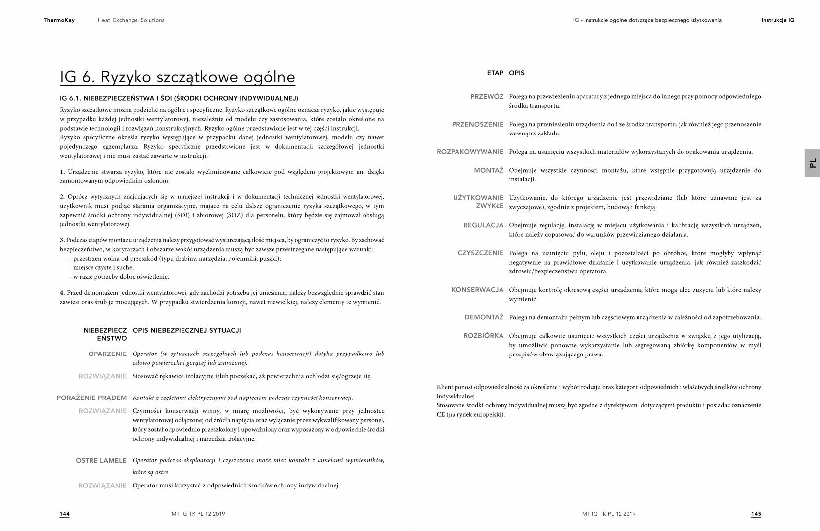
145144
Heat Exchange SolutionsThermoKey IG - Instrukcje ogolne dotyczące bezpiecznego użytkowania Instrukcje IG
PL
MT IG TK PL 12 2019MT IG TK PL 12 2019
IG 6. Ryzyko szczątkowe ogólneIG 6.1. NIEBEZPIECZEŃSTWA I ŚOI (ŚRODKI OCHRONY INDYWIDUALNEJ)Ryzyko szczątkowe można podzielić na ogólne i specyficzne. Ryzyko szczątkowe ogólne oznacza ryzyko, jakie występuje w przypadku każdej jednostki wentylatorowej, niezależnie od modelu czy zastosowania, które zostało określone na podstawie technologii i rozwiązań konstrukcyjnych. Ryzyko ogólne przedstawione jest w tej części instrukcji.Ryzyko specyficzne określa ryzyko występujące w przypadku danej jednostki wentylatorowej, modelu czy nawet pojedynczego egzemplarza. Ryzyko specyficzne przedstawione jest w dokumentacji szczegółowej jednostki wentylatorowej i nie musi zostać zawarte w instrukcji.
1. Urządzenie stwarza ryzyko, które nie zostało wyeliminowane całkowicie pod względem projektowym ani dzięki zamontowanym odpowiednim osłonom.
2. Oprócz wytycznych znajdujących się w niniejszej instrukcji i w dokumentacji technicznej jednostki wentylatorowej, użytkownik musi podjąć starania organizacyjne, mające na celu dalsze ograniczenie ryzyka szczątkowego, w tym zapewnić środki ochrony indywidualnej (ŚOI) i zbiorowej (ŚOZ) dla personelu, który będzie się zajmował obsługą jednostki wentylatorowej.
3. Podczas etapów montażu urządzenia należy przygotować wystarczającą ilość miejsca, by ograniczyć to ryzyko. By zachować bezpieczeństwo, w korytarzach i obszarze wokół urządzenia muszą być zawsze przestrzegane następujące warunki:
- przestrzeń wolna od przeszkód (typu drabiny, narzędzia, pojemniki, puszki);- miejsce czyste i suche;- w razie potrzeby dobre oświetlenie.
4. Przed demontażem jednostki wentylatorowej, gdy zachodzi potrzeba jej uniesienia, należy bezwzględnie sprawdzić stan zawiesi oraz śrub je mocujących. W przypadku stwierdzenia korozji, nawet niewielkiej, należy elementy te wymienić.
ROZWIĄZANIE
ROZWIĄZANIE
OPARZENIE
PORAŻENIE PRĄDEM
Operator (w sytuacjach szczególnych lub podczas konserwacji) dotyka przypadkowo lub celowo powierzchni gorącej lub zmrożonej.
Stosować rękawice izolacyjne i/lub poczekać, aż powierzchnia ochłodzi się/ogrzeje się.
Kontakt z częściami elektrycznymi pod napięciem podczas czynności konserwacji.
Czynności konserwacji winny, w miarę możliwości, być wykonywane przy jednostce wentylatorowej odłączonej od źródła napięcia oraz wyłącznie przez wykwalifikowany personel, który został odpowiednio przeszkolony i upoważniony oraz wyposażony w odpowiednie środki ochrony indywidualnej i narzędzia izolacyjne.
Operator podczas eksploatacji i czyszczenia może mieć kontakt z lamelami wymienników,
które są ostre
Operator musi korzystać z odpowiednich środków ochrony indywidualnej.ROZWIĄZANIE
OSTRE LAMELE
OPIS NIEBEZPIECZNEJ SYTUACJINIEBEZPIECZEŃSTWO
Klient ponosi odpowiedzialność za określenie i wybór rodzaju oraz kategorii odpowiednich i właściwych środków ochrony indywidualnej.Stosowane środki ochrony indywidualnej muszą być zgodne z dyrektywami dotyczącymi produktu i posiadać oznaczenie CE (na rynek europejski).
ETAP OPIS
PRZEWÓZ
PRZENOSZENIE
ROZPAKOWYWANIE
MONTAŻ
UŻYTKOWANIE ZWYKŁE
REGULACJA
CZYSZCZENIE
KONSERWACJA
DEMONTAŻ
ROZBIÓRKA
Polega na przewiezieniu aparatury z jednego miejsca do innego przy pomocy odpowiedniego środka transportu.
Polega na przeniesieniu urządzenia do i ze środka transportu, jak również jego przenoszenie wewnątrz zakładu.
Polega na usunięciu wszystkich materiałów wykorzystanych do opakowania urządzenia.
Obejmuje wszystkie czynności montażu, które wstępnie przygotowują urządzenie do instalacji.
Użytkowanie, do którego urządzenie jest przewidziane (lub które uznawane jest za zwyczajowe), zgodnie z projektem, budową i funkcją.
Obejmuje regulację, instalację w miejscu użytkowania i kalibrację wszystkich urządzeń, które należy dopasować do warunków przewidzianego działania.
Polega na usunięciu pyłu, oleju i pozostałości po obróbce, które mogłyby wpłynąć negatywnie na prawidłowe działanie i użytkowanie urządzenia, jak również zaszkodzić zdrowiu/bezpieczeństwu operatora.
Obejmuje kontrolę okresową części urządzenia, które mogą ulec zużyciu lub które należy wymienić.
Polega na demontażu pełnym lub częściowym urządzenia w zależności od zapotrzebowania.
Obejmuje całkowite usunięcie wszystkich części urządzenia w związku z jego utylizacją, by umożliwić ponowne wykorzystanie lub segregowaną zbiórkę komponentów w myśl przepisów obowiązującego prawa.
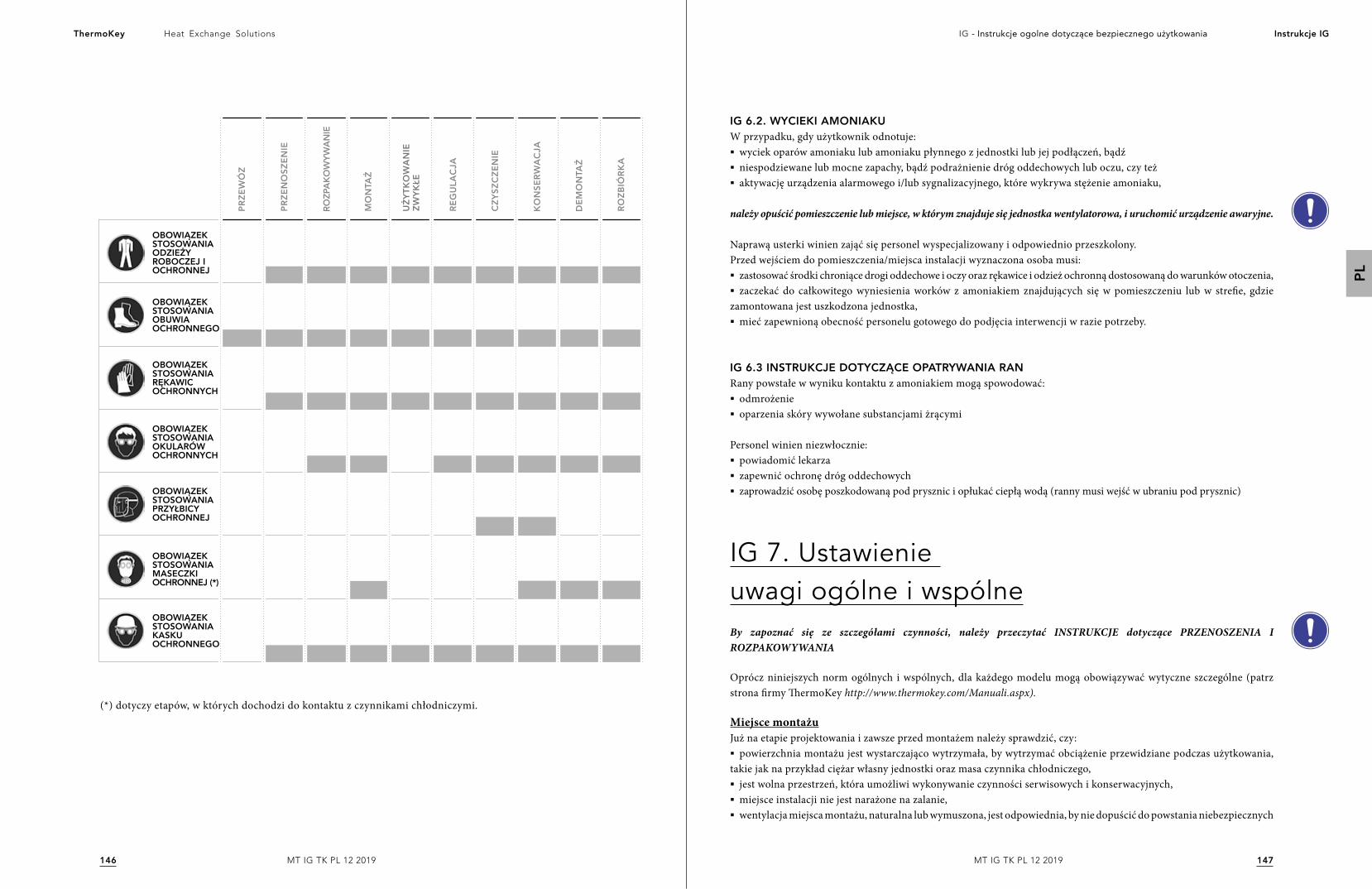
147146
Heat Exchange SolutionsThermoKey IG - Instrukcje ogolne dotyczące bezpiecznego użytkowania Instrukcje IG
PL
MT IG TK PL 12 2019MT IG TK PL 12 2019
OBOWIĄZEK STOSOWANIA ODZIEŻY ROBOCZEJ I OCHRONNEJ
OBOWIĄZEK STOSOWANIA PRZYŁBICY OCHRONNEJ
OBOWIĄZEK STOSOWANIA KASKU OCHRONNEGO
OBOWIĄZEK STOSOWANIA RĘKAWIC OCHRONNYCH
OBOWIĄZEK STOSOWANIA OBUWIA OCHRONNEGO
OBOWIĄZEK STOSOWANIA MASECZKI OCHRONNEJ (*)
OBOWIĄZEK STOSOWANIA OKULARÓW OCHRONNYCH
PRZE
WÓ
Z
PRZE
NO
SZEN
IE
ROZP
AKO
WYW
AN
IE
MO
NTA
Ż
REG
ULA
CJA
CZY
SZC
ZEN
IE
KO
NSE
RWA
CJA
DEM
ON
TAŻ
ROZB
IÓRK
A
UŻY
TKO
WA
NIE
ZW
YKŁE
(*) dotyczy etapów, w których dochodzi do kontaktu z czynnikami chłodniczymi.
IG 6.2. WYCIEKI AMONIAKUW przypadku, gdy użytkownik odnotuje:§ wyciek oparów amoniaku lub amoniaku płynnego z jednostki lub jej podłączeń, bądź§ niespodziewane lub mocne zapachy, bądź podrażnienie dróg oddechowych lub oczu, czy też§ aktywację urządzenia alarmowego i/lub sygnalizacyjnego, które wykrywa stężenie amoniaku,
należy opuścić pomieszczenie lub miejsce, w którym znajduje się jednostka wentylatorowa, i uruchomić urządzenie awaryjne.
Naprawą usterki winien zająć się personel wyspecjalizowany i odpowiednio przeszkolony.Przed wejściem do pomieszczenia/miejsca instalacji wyznaczona osoba musi:§ zastosować środki chroniące drogi oddechowe i oczy oraz rękawice i odzież ochronną dostosowaną do warunków otoczenia,§ zaczekać do całkowitego wyniesienia worków z amoniakiem znajdujących się w pomieszczeniu lub w strefie, gdzie
zamontowana jest uszkodzona jednostka,§ mieć zapewnioną obecność personelu gotowego do podjęcia interwencji w razie potrzeby.
IG 6.3 INSTRUKCJE DOTYCZĄCE OPATRYWANIA RANRany powstałe w wyniku kontaktu z amoniakiem mogą spowodować:§ odmrożenie§ oparzenia skóry wywołane substancjami żrącymi
Personel winien niezwłocznie:§ powiadomić lekarza§ zapewnić ochronę dróg oddechowych§ zaprowadzić osobę poszkodowaną pod prysznic i opłukać ciepłą wodą (ranny musi wejść w ubraniu pod prysznic)
IG 7. Ustawienie uwagi ogólne i wspólneBy zapoznać się ze szczegółami czynności, należy przeczytać INSTRUKCJE dotyczące PRZENOSZENIA I ROZPAKOWYWANIA
Oprócz niniejszych norm ogólnych i wspólnych, dla każdego modelu mogą obowiązywać wytyczne szczególne (patrz strona firmy ThermoKey http://www.thermokey.com/Manuali.aspx).
Miejsce montażuJuż na etapie projektowania i zawsze przed montażem należy sprawdzić, czy:§ powierzchnia montażu jest wystarczająco wytrzymała, by wytrzymać obciążenie przewidziane podczas użytkowania,
takie jak na przykład ciężar własny jednostki oraz masa czynnika chłodniczego,§ jest wolna przestrzeń, która umożliwi wykonywanie czynności serwisowych i konserwacyjnych,§ miejsce instalacji nie jest narażone na zalanie,§ wentylacja miejsca montażu, naturalna lub wymuszona, jest odpowiednia, by nie dopuścić do powstania niebezpiecznych
149148
Heat Exchange SolutionsThermoKey IG - Instrukcje ogolne dotyczące bezpiecznego użytkowania Instrukcje IG
PL
MT IG TK PL 12 2019MT IG TK PL 12 2019
stężeń czynników chłodniczych, potencjalnie wybuchowych lub łatwopalnych,§ temperatura pomieszczenia, w którym znajduje się jednostka podczas etapów przestoju w pracy, nie może przekroczyć 50°C,§ można zastosować wibroizolatory i przyłącza elastyczne na orurowaniu, by ograniczyć maksymalnie rozprzestrzenianie
wibracji w budynku,§ wpływ hałasu mieści się w odpowiednich granicach.
W przypadku montażu wewnątrz należy ponadto sprawdzić, czy pomieszczenie, w którym jednostka jest instalowana, jest zgodne z wytycznymi normy EN 378-3 oraz innymi specyfikacjami technicznymi oraz przepisami obowiązującymi wobec miejsca instalacji.
W przypadku montażu na zewnątrz należy ponadto sprawdzić,§ czy umiejscowienie jednostki jest na poziomie wyższym niż średnia wysokość pokrywy śnieżnej,§ sprawdzić, czy powierzchnia montażu jest wystarczająco wytrzymała, by wytrzymać obciążenie przewidziane podczas
użytkowania zwykłego, takie jak na przykład ciężar własny jednostki oraz masa czynnika chłodniczego, jak również obciążenie przypadkowe, np. od śniegu, wiatru i podobnych, również w odniesieniu do normy EN 1991-5.
Przygotować miejsce i narzędzia niezbędne do montażu.
Zwrócić szczególną uwagę na niebezpieczeństwo korozji galwanicznej; szczególnym obowiązkiem projektanta/montera jest zapewnienie odpowiedniego systemu zabezpieczeń.
Przewidzieć (jest to obowiązek montera/projektanta) możliwe drgania zewnętrzne, na przykład ruch uliczny w pobliżu dróg, drgania w pobliżu lotnisk itd.
Zaleca się montaż wibroizolatorów na podstawie konstrukcji: należy odnieść się do katalogu lub sprawdzić na stronie internetowej www.thermokey.com w zakładce Do pobrania, Katalog.W celu wykonania obliczeń szacunkowych zaleca się odniesienie do normy EN 1991-6.
Zastosowanie systemów antywibracyjnych może zmienić warunki wytrzymałości na obciążenie jednostki wentylatorowej (w szczególności na wiatr i drgania własne).
W celu zwymiarowania orurowania, w szczególności przeznaczonego do amoniaku i czynników chłodniczych z grupy 1, zaleca się zastosowanie normy EN 1998-6.
Wybierając miejsce instalacji, należy wziąć pod uwagę szereg możliwych zagrożeń, które mogą wystąpić zarówno na etapie montażu, jak i na kolejnych etapach użytkowania zwyczajnego oraz demontażu. Obowiązkiem projektanta montera i/lub użytkownika jest ocena ryzyka występującego w miejscu montażu. Wykaz przykładowy, lecz niewyczerpujący, znajduje się poniżej.
Obszar wokół lub powierzchnia pod jednostką wentylatorową mogą okazać się śliskie: należy oznaczyć należycie takie ryzyko
wszystkie konstrukcje wystające poza jednostkę wentylatorową mogą powodować ryzyko potknięcia.
W przypadku jednostek wentylatorowych podwieszanych lub zawieszonych oraz jednostek wentylatorowych o dużych rozmiarach możliwe jest wystąpienie ryzyka uderzenia w głowę ze względu na wysokość montażu.
W przypadku montażu na wysokości (na tarasach dachowych, konstrukcjach nośnych lub w podobnych miejscach, przekraczających wysokość 2 m od powierzchni podłoża), istnieje ryzyko upadku z wysokości, które musi zostać ograniczone dzięki użyciu odpowiednich środków ochrony zbiorowej.
Zastosowanie amoniaku i czynników chłodniczych z grupy 1 może spowodować ryzyko wybuchu w wyniku wytworzenia atmosfery wybuchowej. Na etapie projektowania należy zawsze przestrzegać wszystkich niezbędnych środków ostrożności, by uniknąć tego niebezpieczeństwa.
IG 7.1. MINIMALNE POWIERZCHNIE TECHNICZNEMinimalne powierzchnie techniczne mogą różnić się w zależności od zastosowania, zatem konieczne jest przestrzeganie szczegółowych wytycznych określonych w dokumentacji technicznej. Jeśli nie ma takich wytycznych, należy zgłosić się po nie niezwłocznie do firmy ThermoKey.
IG 7.2. KONTROLA W MOMENCIE DOSTAWYSprawdzić zgodność potwierdzenia zamówienia z danymi wskazanymi na tabliczce znamionowej i sprawdzić zgodność parametrów elektrycznych z parametrami pożądanymi. Nie należy rozpoczynać montażu, jeśli występuje niezgodność parametrów.
Jeśli jednostka wentylatorowa ma wadę w momencie rozpakowania i/lub montażu, natychmiast zgłosić ten fakt producentowi i nie kontynuować kolejnych etapów bez wyraźnego upoważnienia.
IG 7.3. ROZPAKOWYWANIE JEDNOSTKIOpakowania mogą być różnego rodzaju, zatem należy przestrzegać szczegółowych wytycznych określonych w dokumentacji technicznej. Jeśli nie ma takich wytycznych, należy zgłosić się po nie niezwłocznie do firmy ThermoKey, wstrzymując się z wszelkimi czynnościami rozpakowywania.
IG 7.4 UMIESZCZENIEZabrania się przechodzenia przez konstrukcję i przebywania w promieniu działania wszelkich urządzeń dźwignicowych.
Jeśli występuje, należy obowiązkowo zdjąć folię ochronną z osłony po zakończeniu montażu.
W przypadku montażu, którego wykonywanie wymaga prac na wysokości lub powoduje narażenie na ryzyko upadku, nie wolno korzystać z drabiny, lecz należy przestrzegać przepisów krajowych obowiązujących w zakresie bezpieczeństwa „prac na wysokościach”.
Prace na wysokości mogą być przeprowadzane wyłącznie przy sprzyjających warunkach atmosferycznych, które nie zagrożą bezpieczeństwu pracowników.
151150
Heat Exchange SolutionsThermoKey IG - Instrukcje ogolne dotyczące bezpiecznego użytkowania Instrukcje IG
PL
MT IG TK PL 12 2019MT IG TK PL 12 2019
IG 8. MontażMontaż to kolejny etap po umieszczeniu jednostki wentylatorowej, podczas którego wykonywane są czynności mocowania jednostki do podpory, umieszczane są wiatrownice, ewentualnie wykonywany jest ponowny montaż elementów rozmontowanych dla celów przenoszenia.
Montaż należy wykonać zgodnie z wytycznymi wskazanymi w instrukcji oraz zgodnie z wytycznymi normy EN 378-3.
Mocowanie mechaniczne jednostki wentylatorowej stanowi obowiązek montera. Jednostka wentylatorowa jest wyposażona w otwory mocujące. Jeśli wymiary otworów okażą się niewystarczające, nie wolno powiększać ich bez uprzedniej zgody ze strony firmy ThermoKey.
Wymiary otworów mocujących są wynikiem obliczeń statycznych wykonanych przez producenta. Elementy mocujące muszą być zgodne z wymiarami otworów.Elementy mocujące muszą być wyposażone we wszelkie niezbędne środki, by nie dopuścić do ich poluzowania.
W celu zwymiarowania urządzeń kotwiących lub mocujących jednostki wentylatorowej, należy wdrożyć normy odniesienia ETAG i odnieść się do katalogów technicznych, dostępnych na stronie internetowej www.thermokey.com w zakładce Do pobrania, Katalog.
By poprawić stabilność i wytrzymałość jednostek wentylatorowych montowanych na zewnątrz na obciążenie wiatrem, można zastosować wiatrownice. Wybór i decyzja o wymiarach wiatrownic należą do montera.
IG 9. PrzyłączaKategorycznie zabrania się zmiany położenia kolektorów. Kolektory nie mogą być przesuwane przy użyciu siły z ich oryginalnego rozmieszczenia.
§ Przygotowując przyłącza IN/OUT, obowiązkowe jest sprawdzenie kierunku przepływu zastosowanego czynnika chłodniczego na wysokości kolektorów lub kołnierzy. § Zaleca się montaż zaworów odcinających przed nimi, by ułatwić czynności konserwacji. Jeśli montaż tych zaworów powoduje
ryzyko, obowiązkiem montera jest zapewnienie odpowiednich rozwiązań w zakresie obiegów.§ W przypadku skraplaczy i chłodnic suchych typu V wyposażonych w system AFS (Air Fresh System), jeśli przewidywana jest
temperatura otoczenia poniżej 0°C, obowiązkowe jest opróżnienie systemu z wody zasilającej, by wyeliminować ryzyko zamarzania.§ W przypadku przyłączy należy obowiązkowo przestrzegać wymiarów przygotowanych złączy. Jakikolwiek rodzaj
modyfikacji musi zostać uprzednio uzgodniony z Biurem Klienta ThermoKey pod rygorem wygaśnięcia wszelkiej odpowiedzialności dotyczącej szkód odnoszących się do osób, zwierząt lub rzeczy, obniżenia osiągów w stosunku do osiągów deklarowanych, a także pod rygorem wygaśnięcia Warunków gwarancji.
IG 9.1. PODŁĄCZENIA HYDRAULICZNEPodłączenia hydrauliczne muszą zostać wykonane zgodnie z przepisami krajowymi lub miejscowymi. Przyłącza mogą być wykonane ze stali, stali ocynkowanej lub PVC. Przyłącza muszą być prawidłowo zwymiarowane w zależności od nominalnego przepływu czynnika chłodniczego, ciśnienia, oporów w obiegu hydraulicznym oraz temperatury roboczej. Wszystkie podłączenia hydrauliczne muszą mieć izolację wykonaną z materiału z zamkniętymi porami o odpowiedniej grubości..
IG 9.2. MONTAŻ PRZYŁĄCZY§ Przymocować prawidłowo wszystkie przyłącza, unikając powstania uszkodzeń mechanicznych, postępując zgodnie z dobrą praktyką
montażu oraz wytycznymi znajdującymi się w Specyfikacjach technicznych w zakładce Do pobrania na stronie www.thermokey.com§ Podczas dokręcania podtrzymywać przyłącza tak, by nie obciążyć w niepożądany sposób systemów mocowania.§ Jeśli montaż odbywa się w miejscach, w których dozwolone jest przechodzenie personelu, umieścić przyłącza tak, by nie
stanowiły one przeszkody, oraz upewnić się, że przewody są podłączone przy pomocy złączek, których nie da się łatwo usunąć.§ Stosować podpory mocujące dostosowane do wagi przyłączy, tak by cały ciężar nie opierał się na połączeniach, co
mogłoby spowodować ich uszkodzenie i odłamanie od jednostki.
W jednostkach wentylatorowych, w których stosowany jest amoniak lub płyny wybuchowe bądź łatwopalne, nieprawidłowy montaż przewodów powoduje ryzyko wycieku czynnika chłodniczego.
IG 9.3. SPAWANIE§ W przypadku wykonywania czynności łączenia przy pomocy spawania, należy spawać uważnie i precyzyjnie aby nie
dopuścić do wycieków;§ unikać przegrzania podczas spawania (niebezpieczeństwo nadmiernych zmian wymiarów);§ stosować gaz osłonowy do spawania (unikać nadmiernych zanieczyszczeń):§ prace spawalnicze w obrębie komponentów pod napięciem mogą spowodować pożary lub wybuchy; § wykonywać prace spawalnicze wyłącznie przy odłączonej jednostce i przy wyłączonym napięciu;§ upewnić się, że ładunek i drgania nie obciążają nadmiernie jednostki;§ podczas spawania połączeń, zabrania się prowadzić płomień w kierunku jednostki i/lub ewentualnych zamontowanych
urządzeń elektrycznych.
IG 10. Podłączenie elektrycznePodłączenia elektryczne muszą być wykonane zgodnie z niniejszą instrukcją i schematami elektrycznymi załączonymi do Instrukcji i danych technicznych oraz zgodnie z przepisami dotyczącymi instalacji elektrycznych obowiązującymi w kraju, w którym jednostka jest montowana.
Obowiązkowo należy wykonać uziemienie urządzenia.
§ Podłączenie elektryczne musi być wykonane przez wykwalifikowany personel, spełniający niezbędne wymogi techni-czne , ustalone w kraju, w którym przeprowadzany jest montaż jednostki.§ Należy obowiązkowo sprawdzić, czy napięcie sieci odpowiada napięciu wskazanemu na tabliczce znamionowej.§ Wybór i wymiarowanie przewodu zasilania jednostki wentylatorowej należy do projektanta/montera.§ Podczas układania przewodu zasilania zaleca się zastosowanie kanalizacji lub osłon przewodów, które zabezpieczą go
w sposób mechaniczny. Zaleca się ułożenie bez przymocowania.§ Obowiązkowe jest użycie przewodów zasilających o rodzaju i przekroju minimalnym zgodnym z EN 60204-1 oraz,
ewentualnie, z przepisami technicznymi obowiązującymi w kraju montażu.§ Napięcie oraz prąd niezbędny do zwymiarowania przewodu elektrycznego głównej instalacji zaznaczone są na tabli-
czce znamionowej i/lub w katalogach technicznych.§ Obowiązkowo należy wyposażyć instalację zasilania elektrycznego w zabezpieczenie nadprądowe i nadnapięciowe. § Przewód elektryczny musi być wprowadzany do rozdzielnic i skrzynek elektrycznych jednostki wentylatorowej od dołu,
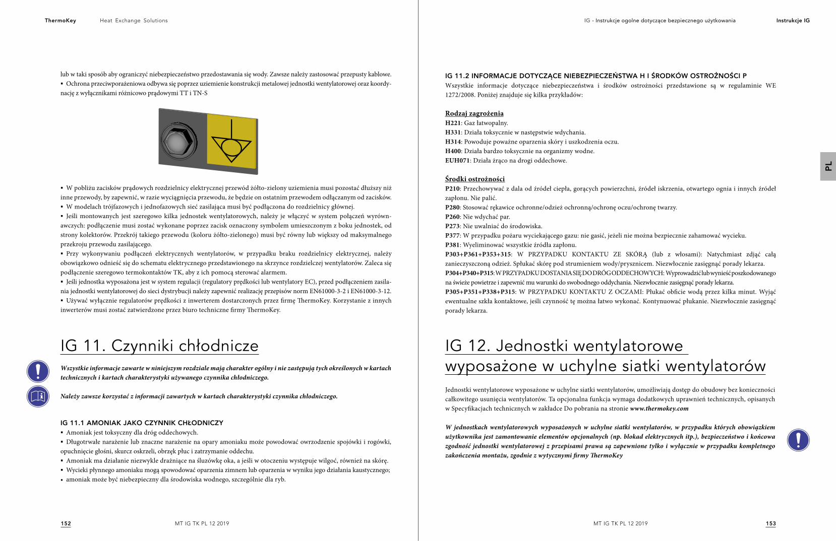
153152
Heat Exchange SolutionsThermoKey IG - Instrukcje ogolne dotyczące bezpiecznego użytkowania Instrukcje IG
PL
MT IG TK PL 12 2019MT IG TK PL 12 2019
lub w taki sposób aby ograniczyć niebezpieczeństwo przedostawania się wody. Zawsze należy zastosować przepusty kablowe.§ Ochrona przeciwporażeniowa odbywa się poprzez uziemienie konstrukcji metalowej jednostki wentylatorowej oraz koordy-
nację z wyłącznikami różnicowo prądowymi TT i TN-S
IG 11. Czynniki chłodniczeWszystkie informacje zawarte w niniejszym rozdziale mają charakter ogólny i nie zastępują tych określonych w kartach technicznych i kartach charakterystyki używanego czynnika chłodniczego.
Należy zawsze korzystać z informacji zawartych w kartach charakterystyki czynnika chłodniczego.
IG 11.1 AMONIAK JAKO CZYNNIK CHŁODNICZY§ Amoniak jest toksyczny dla dróg oddechowych.§ Długotrwałe narażenie lub znaczne narażenie na opary amoniaku może powodować owrzodzenie spojówki i rogówki,
opuchnięcie głośni, skurcz oskrzeli, obrzęk płuc i zatrzymanie oddechu.§ Amoniak ma działanie niezwykle drażniące na śluzówkę oka, a jeśli w otoczeniu występuje wilgoć, również na skórę.§ Wycieki płynnego amoniaku mogą spowodować oparzenia zimnem lub oparzenia w wyniku jego działania kaustycznego;
• amoniak może być niebezpieczny dla środowiska wodnego, szczególnie dla ryb.
IG 12. Jednostki wentylatorowe wyposażone w uchylne siatki wentylatorówJednostki wentylatorowe wyposażone w uchylne siatki wentylatorów, umożliwiają dostęp do obudowy bez konieczności całkowitego usunięcia wentylatorów. Ta opcjonalna funkcja wymaga dodatkowych uprawnień technicznych, opisanych w Specyfikacjach technicznych w zakładce Do pobrania na stronie www.thermokey.com
W jednostkach wentylatorowych wyposażonych w uchylne siatki wentylatorów, w przypadku których obowiązkiem użytkownika jest zamontowanie elementów opcjonalnych (np. blokad elektrycznych itp.), bezpieczeństwo i końcowa zgodność jednostki wentylatorowej z przepisami prawa są zapewnione tylko i wyłącznie w przypadku kompletnego zakończenia montażu, zgodnie z wytycznymi firmy ThermoKey
IG 11.2 INFORMACJE DOTYCZĄCE NIEBEZPIECZEŃSTWA H I ŚRODKÓW OSTROŻNOŚCI PWszystkie informacje dotyczące niebezpieczeństwa i środków ostrożności przedstawione są w regulaminie WE 1272/2008. Poniżej znajduje się kilka przykładów:
Rodzaj zagrożeniaH221: Gaz łatwopalny. H331: Działa toksycznie w następstwie wdychania. H314: Powoduje poważne oparzenia skóry i uszkodzenia oczu. H400: Działa bardzo toksycznie na organizmy wodne. EUH071: Działa żrąco na drogi oddechowe.
Środki ostrożnościP210: Przechowywać z dala od źródeł ciepła, gorących powierzchni, źródeł iskrzenia, otwartego ognia i innych źródeł zapłonu. Nie palić.P280: Stosować rękawice ochronne/odzież ochronną/ochronę oczu/ochronę twarzy. P260: Nie wdychać par. P273: Nie uwalniać do środowiska. P377: W przypadku pożaru wyciekającego gazu: nie gasić, jeżeli nie można bezpiecznie zahamować wycieku.P381: Wyeliminować wszystkie źródła zapłonu. P303+P361+P353+315: W PRZYPADKU KONTAKTU ZE SKÓRĄ (lub z włosami): Natychmiast zdjąć całą zanieczyszczoną odzież. Spłukać skórę pod strumieniem wody/prysznicem. Niezwłocznie zasięgnąć porady lekarza. P304+P340+P315: W PRZYPADKU DOSTANIA SIĘ DO DRÓG ODDECHOWYCH: Wyprowadzić lub wynieść poszkodowanego na świeże powietrze i zapewnić mu warunki do swobodnego oddychania. Niezwłocznie zasięgnąć porady lekarza. P305+P351+P338+P315: W PRZYPADKU KONTAKTU Z OCZAMI: Płukać obficie wodą przez kilka minut. Wyjąć ewentualne szkła kontaktowe, jeśli czynność tę można łatwo wykonać. Kontynuować płukanie. Niezwłocznie zasięgnąć porady lekarza.
§ W pobliżu zacisków prądowych rozdzielnicy elektrycznej przewód żółto-zielony uziemienia musi pozostać dłuższy niż inne przewody, by zapewnić, w razie wyciągnięcia przewodu, że będzie on ostatnim przewodem odłączanym od zacisków. § W modelach trójfazowych i jednofazowych sieć zasilająca musi być podłączona do rozdzielnicy głównej.§ Jeśli montowanych jest szeregowo kilka jednostek wentylatorowych, należy je włączyć w system połączeń wyrówn-
awczych: podłączenie musi zostać wykonane poprzez zacisk oznaczony symbolem umieszczonym z boku jednostek, od strony kolektorów. Przekrój takiego przewodu (koloru żółto-zielonego) musi być równy lub większy od maksymalnego przekroju przewodu zasilającego.§ Przy wykonywaniu podłączeń elektrycznych wentylatorów, w przypadku braku rozdzielnicy elektrycznej, należy
obowiązkowo odnieść się do schematu elektrycznego przedstawionego na skrzynce rozdzielczej wentylatorów. Zaleca się podłączenie szeregowo termokontaktów TK, aby z ich pomocą sterować alarmem.§ Jeśli jednostka wyposażona jest w system regulacji (regulatory prędkości lub wentylatory EC), przed podłączeniem zasila-
nia jednostki wentylatorowej do sieci dystrybucji należy zapewnić realizację przepisów norm EN61000-3-2 i EN61000-3-12.§ Używać wyłącznie regulatorów prędkości z inwerterem dostarczonych przez firmę ThermoKey. Korzystanie z innych
inwerterów musi zostać zatwierdzone przez biuro techniczne firmy ThermoKey.
MT IG TK PL 12 2019P
LОбщие указаниядля безопасного использования
Система управления качеством ISO 9001 Система экологического менеджмента ISO 14001Система управления производственной
безопасностью и охраной труда BS OHSAS 18001
ОРИГИНАЛ ИНСТРУКЦИИ ИЗДАННА ИТАЛЬЯНСКОМ ЯЗЫКЕ
156155
Heat Exchange SolutionsThermoKey И.Г. Общие инструкции по безопасному Руководства IG
MT IG TK RU 12 2019MT IG TK RU 12 2019
RU
ПЕРЕДПРОЕКТНЫМИРАБОТАМИ,АТАКЖЕЛЮБЫМИОПЕРАЦИЯМИПОПЕРЕМЕЩЕНИЮ,СНЯТИЮУПАКОВКИ,УСТАНОВКЕИВВОДЕВЭКСПЛУАТАЦИЮОБОРУДОВАНИЯВНИМАТЕЛЬНОПРОЧИТАТЬЭТУИНСТРУКЦИЮИУБЕДИТЬСЯВТОМ,ЧТОЕЕСОДЕРЖАНИЕБЫЛОПОНЯТО
ThermoKey снимает с себя ответственность за ущерб, нанесенный людям или имуществу в результате несоблюдения инструкций, содержащихся в этом документе.
Оригинал этого руководства находится в итальянский и доступен на сайте: www.thermokey.com Перевод в английский соответствует оригиналу и его можно найти на сайте: www.thermokey.com Переводы на другие языки могут содержать ошибки; в случае сомнений всегда обращайтесь к оригинальной версии на итальянском или к ее английскому переводу.
ФИЛОСОФИЯРУКОВОДСТВАКомментарий н. 255 пересмотренных руководств по применению 2 Директивы по машинному оборудованию 2006/42 / EC предлагает предоставить электронный формат, доступный в Интернете, с инструкциями, чтобы избежать их потери и способствовать их обновлению.Кроме того, комментарий 275 требует, чтобы было соответствие между технико-коммерческими публикациями, такими как каталоги, и руководством.Многие из вентилируемых блоков, производимых hermoKey, настроены для конкретного завода или клиента.Исходя из указанных выше пунктов и учитывая, что пользователи инструкций являются разработчиками систем, установщиками и пользователями, техническая документация для правильного проектирования и правильного использования вентилируемого блока соответствует изложению серии из документы, взятые вместе, фактически являются РУКОВОДЯЩИМИ.
ОБЩАЯ ИНСТРУКЦИЯ ПО БЕЗОПАСНОЙ ЭКСПЛУАТАЦИИ (IG)
ИНСТРУКЦИЯ ПО ОБРАЩЕНИЮ И РАСПАКОВКЕ (IM)
ИНСТРУКЦИЯ И ТЕХНИЧЕСКИЕ ДАННЫЕ (TC)
СПЕЦИАЛЬНЫЕ ИНСТРУКЦИИ ПО ЭКСПЛУАТАЦИИ И ОБСЛУЖИВАНИЮ (IS)
СОДЕРЖАНИЕРУКОВОДСТВА
158157
Heat Exchange SolutionsThermoKey И.Г. Общие инструкции по безопасному Руководства IG
MT IG TK RU 12 2019MT IG TK RU 12 2019
RU
В Общих инструкциях по безопасной эксплуатации приводится информация о безопасности и правильной эксплуатации, в том числе:
IG1. ПРЕДВАРИТЕЛЬНЫЕЗАМЕЧАНИЯ
IG2. ЮРИДИЧЕСКАЯИНФОРМАЦИЯIG 2.1 ОРИГИНАЛЬНАЯ ВЕРСИЯIG 2.2 ПРЕДЕЛЫ ИСПОЛЬЗОВАНИЯ НАСТОЯЩЕГО РУКОВОДСТВАIG 2.3 СОДЕРЖАНИЕ И ПОНИМАНИЕ РУКОВОДСТВАIG 2.4 ОТВЕТСТВЕННОСТЬIG 2.5 ЮРИДИЧЕСКИЕ И ТЕХНИЧЕСКИЕ НОРМЫ, ИСПОЛЬЗУЕМЫЕ В КОНСТРУКЦИИ ЛОКАIG 2.6 ЗНАЧЕНИЕ СЕРИИ НОРМЫ EN378
IG3. ТАБЛИЧКИИОБЩИЕЭТИКЕТКИ
IG4. ОБЩИЕПРЕДУПРЕЖДЕНИЯИПРАВИЛАБЕЗОПАСНОСТИIG 4.1 ОБЩАЯ ИНФОРМАЦИЯIG 4.2 ПЕРЕМЕЩЕНИЯ ПРИ ЗАГРУЗКЕ И ВЫГРУЗКЕIG 4.3 ТРАНСПОРТИРОВКАIG 4.4 ХРАНЕНИЕ IG 4.5 ПРИМЕЧАНИЯ ДЛЯ ВЕНТИЛЯТОРОВ IG 4.6 ЭЛЕКТРОБЕЗОПАСНОСТЬIG 4.7 МЕХАНИЧЕСКАЯ БЕЗОПАСНОСТЬ
IG5. НЕПРАВИЛЬНАЯИЗАПРЕЩЕННАЯЭКСПЛУАТАЦИЯIG 5.1 ОСОБЫЕ ЗАПРЕТЫ ДЛЯ ВЕНТИЛЯЦИОННЫХ БЛОКОВ В СРЕДЕ АММИАКА
IG6. ОБЩИЕОСТАТОЧНЫЕРИСКИIG 6.1 СРЕДСТВА ИНДИВИДУАЛЬНОЙ ЗАЩИТЫ И ОПАСНОСТИIG 6.2 УТЕЧКА АММИАКА IG 6.3 ИНСТРУКЦИИ ПО УСТРАНЕНИЮ ПОВРЕЖДЕНИЙ
IG7. РАСПОЛОЖЕНИЕ-ОБЩИЕЗАМЕЧАНИЯIG 7.1 МИНИМАЛЬНЫЕ ТЕХНИЧЕСКИЕ РАССТОЯНИЯIG 7.2 ИНСПЕКТИРОВАНИЕ НА МОМЕНТ ПОСТАВКИIG 7.3 РАСПАКОВКА БЛОКАIG 7.4 РАЗМЕЩЕНИЕ
IG8. УСТАНОВКА
IG9. ОДКЛЮЧЕНИЕОХЛАЖДАЮЩИХИВОДНЫХСИСТЕМIG 9.1 ГИДРАВЛИЧЕСКИЕ ПОДКЛЮЧЕНИЯIG 9.2 МОНТАЖ ТРУБIG 9.3 СВАРКА
IG10. ЭЛЕКТРИЧЕСКИЕПОДКЛЮЧЕНИЯ
СОДЕРЖАНИЕ
159
160160160160161163163
163
163163164164164165165165
166166
167167170170
170172172172172
173
173174174174
174
§ В Инструкциях по обращению и распаковке указаны, в пронумерованном порядке, операции, необходимые и разрешенные для перемещения и распаковки различных вентиляционных блоков. В случае специальных вентиляционных блоков правильная информация указывается в документе по номеру подтверждения заказа.
Для облегчения обновления и недопущения двусмысленности информации эта часть документации вентиляционного блока состоит из каталогов и другой технической документации, предоставленной непосредственно со стороны ThermoKey и/или доступной на веб-сайте. www.thermokey.com.
§ В главе Инструкции по TC и технические данные соответствующая техническая информация приведена для каждого отдельного типа вентиляционного блока, сгруппированная по семействам, и включает в себя:
- РАЗМЕРЫ И ВЕС- ГАБАРИТНЫЕ РАЗМЕРЫ И МИНИМАЛЬНЫЕ ТЕХНИЧЕСКИЕ РАССТОЯНИЯ- АЭРАВЛИЧЕСКИЕ, ЭКСПЛУАТАЦИОННЫЕ И ЭЛЕКТРИЧЕСКИЕ ДАННЫЕ- УРОВЕНЬ ЗВУКОВОГО ИЗЛУЧЕНИЯ- ЭЛЕКТРИЧЕСКИЕ СХЕМЫ- ТЕХНИЧЕСКИЙ БЮЛЛЕТЕНЬ
Для облегчения обновления и недопущения двусмысленности информации эта часть документации вентиляционного блока состоит из каталогов и другой технической документации, предоставленной непосредственно со стороны ThermoKey и/или доступной на веб-сайте. www.thermokey.com
Особые инструкции по эксплуатации и обслуживанию являются специфической частью для каждой модели и, возможно, для каждого конкретного вентиляционного блока и включают в себя:
IS 1 - РУКОВОДСТВО ПО ЭКСПЛУАТАЦИИIS 2 - ПРОБЛЕМЫ В РАБОТЕIS 3 - ОБСЛУЖИВАНИЕIS 4 - ЗАПАСНЫЕ ЧАСТИ
IG11. ХЛАДАГЕНТЫIG 11.1 АММИАК В КАЧЕСТВЕ ХЛАДАГЕНТА IG 11.2 УКАЗАНИЯ ПО БЕЗОПАСНОСТИ И ОСТОРОЖНОСТИ
IG12. ИНСПЕКТИРУЕМЫЕВЕНТИЛЯЦИОННЫЕБЛОКИ
175175175
176
160159
Heat Exchange SolutionsThermoKey И.Г. Общие инструкции по безопасному Руководства IG
MT IG TK RU 12 2019MT IG TK RU 12 2019
RU
IG 1. Предварительные замечания БЛОКДОЛЖЕНИСПОЛЬЗОВАТЬСЯДЛЯЦЕЛЕЙ,ДЛЯКОТОРЫХОНБЫЛСОЗДАН.СМ.РАЗДЕЛПРЕДВАРИТЕЛЬНЫЕЗАМЕЧАНИЯ
1. Предварительные замечания являются неотъемлемой частью руководства, поэтому их следует внимательно прочитать и понять.
2. Данное руководство является частью технической документации вентиляционного блока. Данное руководство может быть дополнено другими указаниями и частично изменено в соответствии с индивидуальными требованиями или нестандартными условиями эксплуатации. В общих чертах, руководство состоит из основной части и некоторых технических приложений. Для простоты в дальнейшем "руководство" будет означать всю техническую документацию, необходимую для правильной эксплуатации вентиляционного блока.
3. Сохраняйте данное руководство в течение всего срока службы вентиляционного блока.
4. Обращайте особое внимание на правила эксплуатации, приводимые в руководстве, так как их несоблюдение может привести к повреждению вентиляционного блока и/или людей, животных или имущества.
5. ThermoKey оставляет за собой право изменять настоящее руководство в любое время; изменения в своей последней форме всегда публикуются на сайте www.thermokey.com. Для проверки наличия последней редакции см. индекс редакции
6. Данные изготовителя и ссылка на номер заказа клиента указаны на идентификационной табличке вентиляционного блока, которая содержит, помимо данных самого вентиляционного блока, еще и номер заказа.
7. Неоригинальные детали должны быть предварительно одобрены ThermoKey.
8. Вентиляционный блок соответствует Основным требованиям по охране труда и технике безопасности Директивы 2006/42/EC, применимым к положениям стандартных условий эксплуатации или согласованным с заказчиком.
9. Все виды эксплуатации, не предусмотренные и не описанные в настоящем руководстве, и/или не согласованные между пользователем и ThermoKey до строительства/ввода в эксплуатацию вентиляционного блока явно запрещены Ненадлежащая эксплуатация вентиляционного устройства может привести к опасным условиям, за последствия которых ThermoKey не несет какой-либо ответственности.
10. Вентиляционный блок предназначен для эксплуатации только с хладагентами, указанными в заказе, идентифицируемом по номеру, указанному на паспортной табличке.
11. Использование хладагентов, отличных от явно указанных, запрещено.
12. Для использования аммиака и хладагентов группы 1 могут потребоваться дополнительные инструкции и указания по применению относительно указаний, приведенных в настоящих инструкциях, которые в любом случае содержатся в руководстве к вентиляционному блоку.
13. Использование веществ и жидкостей, которые могут повредить, сделать работу вентиляционного блока небезопасной или ухудшить ее, запрещается.
Ссылка на номер заказа очень важна, поскольку она определяет любые настройки и ограничения эксплуатации, согласованные между ThermoKey как производителем и клиентом как пользователем.
14. Все технические данные вентиляционных блоков и все ограничения по их использованию, а также минимальные характеристики, которыми должно обладать место установки, приводятся в технических каталогах.
15. В случае необходимости внесения изменений или модификаций в вентиляционный блок после его создания, но еще до ввода в эксплуатацию, или если условия эксплуатации на месте установки не соответствуют предусмотренным, или же имеется разница между условиями, предусмотренными до создания, и фактическими условиями по месту установки, следует немедленно и обязательно связаться с ThermoKey перед выполнением какого-либо вмешательства, предполагающего внесение изменений. В противном случае Thermokey не несет ответственности.
16. Проектировщик, установщик и/или пользователь должны соблюдать местные правила и нормы, касающиеся установки, эксплуатации и утилизации вентиляционного блока.
17. Под квалифицированным персоналом, где таковой упоминается в настоящем руководстве, понимаются лица, адекватно информированные или контролируемые лицом, имеющим подготовку, знания и опыт для правильного выполнения работы, понимания рисков и избежания опасностей.
18. Касательно условий гарантии см. соглашения, заключенные во время заказа.
19. Полное или частичное воспроизведение данного руководства без письменного разрешения производителя запрещено. Обновленные копии данного руководства можно найти на веб-сайте www.thermokey.com
IG 2. Правовые аспекты IG 2.1. ORIGINAL VERSIONОригинальная версия этого руководства - на итальянском языке и должна сопровождать любой его перевод.Переводы руководства, не авторизованные производителем, не считаются действительными.
Использование несанкционированных копий и/или переводов данного руководства и/или использование переводов без оригинальной версии на итальянском языке освобождает ThermoKey от любой ответственности в случае аварии.
IG 2.2. ОГРАНИЧЕНИЯИСПОЛЬЗОВАНИЯНАСТОЯЩЕГОРУКОВОДСТВАНастоящее руководство по эксплуатации и техническому обслуживанию подготовлено для вентиляционных блоков, предназначенных для рынка Европейского Союза, о чем свидетельствует знак СЕ.
Данное руководство по эксплуатации и техническому обслуживанию не распространяется на размещение на рынке и/или эксплуатацию оборудования в странах за пределами Европейского Союза.
IG 2.3.СОДЕРЖАНИЕИПОНИМАНИЕРУКОВОДСТВАЕсли разработчик, установщик и/или пользователь (в широком смысле и любые операторы) не находят в данном руководстве техническую информацию, необходимую для установки, эксплуатации, технического обслуживания и/или безопасной утилизации оборудования, или у них имеются сомнения по поводу правильной установки, эксплуатации, обслуживания и/или утилизации, настоятельно рекомендуется связаться с ThermoKey; при создании данного руководства по эксплуатации и техническому обслуживанию мы стремились представить как можно более полную и понятную информацию для подготовки и развития навыков пользователей.Непонимание содержания данного руководства или неполное понимание содержащихся в нем указаний являются условием немедленной остановки любой фазы планирования, установки, эксплуатации, технического обслуживания и/или утилизации данного оборудования.
162161
Heat Exchange SolutionsThermoKey И.Г. Общие инструкции по безопасному Руководства IG
MT IG TK RU 12 2019MT IG TK RU 12 2019
RU
Если операторы продолжают выполнять работу, не полностью разобравшись с настоящей инструкцией по эксплуатации и техническому обслуживанию и/или не обладая всеми знаниями и указаниями, необходимыми для осуществления своей деятельности, ThermoKey считается освобожденным от какой-либо ответственности.
ThermoKey считает несоблюдением несообщение о какой-либо ошибке, упущении, опечатке, несоответствии и т. д. данного руководства в отношении инструкций и технических указаний: разработчик, установщик и пользователь (специалисты по техническому обслуживанию) должны незамедлительно сообщать ThermoKey о ситуациях, которые могут привести к снижению безопасности людей, оборудования и окружающей среды, действуя с необходимой компетентностью, профессионализмом, в духе сотрудничества и прилежания.
Любые небрежные, неосторожные действия или же недостаточная техническая и профессиональная компетентность освобождают изготовителя от любой возможной ответственности.
IG 2.4. ОТВЕТСТВЕННОСТЬОтветственность производителя Производитель несет ответственность за проектирование, конструирование, испытания и упаковку вентиляционной установки с целью ее размещения на рынке Европейского Союза. Производитель гарантирует, что вентиляционный блок спроектирован, изготовлен, испытан и упакован в соответствии с основными требованиями, изложенными в применимых директивах ЕС, и что в этом отношении им была проведена соответствующая оценка соответствия.Операции по снятию упаковки, установке, вводу в эксплуатацию, техническому обслуживанию, демонтажу и утилизации не являются обязанностью производителя, который в данных инструкциях предоставляет как можно больше информации по вышеуказанным этапам срока службы вентиляционного блока.Все части оборудования были спроектированы, изготовлены и испытаны таким образом, чтобы выдерживать разумно прогнозируемые нагрузки при использовании по назначению и в разумных пределах: гарантия безопасности и/или эксплуатации не может предоставляться, если оборудование используются в условиях, явно не предусмотренных ThermoKey, и, следовательно, запрещенных
Установка, эксплуатация, техническое обслуживание и/или утилизация оборудования в запрещенных, не предусмотренных и/или, в любом случае, условиях, отличных от предусмотренных ThermoKey, освобождает последнюю от какой-либо возможной ответственности.
Ответственность проектировщика и установщикаУстановщик и/или проектировщик обязаны оценить риски, подготовить транспортные средства и системы аварийного оповещения, тревожных сигналов, сигнализации и защиты, а также подготовить общие инструкции для системы/холодильной системы, частью которой является вентиляционный блок, как предписано в EN 378-4.Задача разработчика и/или установщика также состоит в том, чтобы определить наилучшие и наиболее безопасные средства и режимы для перемещения и, возможно, хранения устройства вне помещений и/или складов производителя. В частности, разработчик и/или установщик несет ответственность за проверку требований, предъявляемых изготовителем, и за соблюдение этапов обработки, транспортировки и хранения.
Ошибочная оценка риска проектировщиком и/или установщиком или неадекватный выбор средств и систем аварийной сигнализации, тревожных сигналов, оповещения и защиты освобождают ThermoKey от любой возможной ответственности.
Проектировщик - это лицо, которое принимает участие на этапе проектирования системы/системы охлаждения, в которой установлен вентиляционный блок, и несет ответственность как за аспект производительности, так и за аспект безопасности. Проектировщик несет ответственность за выбор наиболее подходящих компонентов
для установки, которую он проектирует, в пределах эксплуатации, установленных производителем. Подготовка проектировщика и его навыки должны быть достаточными для четкого понимания содержания данного руководства пользователя и технического обслуживания и любого другого технико-коммерческого документа, связанного с оборудованием, а также должны быть достаточными для запроса каких-либо разъяснений у производителя в плане создания функциональной, безопасной и современной системы/установки. В частности, проектировщик должен быть в состоянии определить разумно предсказуемые условия работы блока (окружающая среда, крепление, нагрузки и напряжения, подключение к электрическим, жидкостным, гидравлическим системам и т. д.) и убедиться, что блок подходит для этих условий.
Неправильная идентификация условий работы вентиляционного блока разработчиком освобождает ThermoKey от любых обязательств.
Если проект был разделен на несколько частей, координатор проекта, кем бы он ни был, будет считаться разработчиком. Установщик - это лицо, которое принимает участие в установке и реализации системы в соответствии с проектными указаниями, спецификациями компонентов, которые определены их производителями, и техническими нормами. Подготовка установщика и его навыки должны быть достаточными для четкого понимания содержания данного руководства пользователя и технического обслуживания и любого другого технико-коммерческого документа, связанного с оборудованием, а также должны быть достаточными для запроса каких-либо разъяснений у производителя в плане создания функциональной, безопасной и современной системы/установки.
Персонал, участвующий в различных этапах монтажа и ввода в эксплуатацию оборудования, должен быть компетентным и обученным. Что касается актуальности, то минимальный уровень, который должен быть гарантирован, - это уровень, описываемый в EN 13313.
Если установка разделена на несколько частей, координатор установки, кем бы он ни был, будет считаться установщиком.
Ответственность эксплуатанта оборудования/холодильной системы Эксплуатант - это лицо, которое использует установку и, следовательно, блок, который является предметом данного руководства по эксплуатации и техническому обслуживанию. Э ксплуатант несет ответственность за техническое обслуживание блока.
Персонал, участвующий в различных этапах монтажа и ввода в эксплуатацию оборудования, должен быть компетентным и обученным. Что касается актуальности, то минимальный уровень, который должен быть гарантирован, - это уровень, описываемый в EN 13313.
Эксплуатант обязан использовать только компетентный и обученный персонал, оснащенный необходимыми средствами индивидуальной защиты, на этапах управления, технического обслуживания, ремонта, аварийной ситуации и утилизации установки.
Пожалуйста, обратите внимание, что ThermoKey не отвечает за проектирование установки/системы охлаждения, поэтому она освобождается от каких-либо последствий и/или обязательств, возникающих в результате неправильного проектирования/установки.
Обратите внимание, что установки могут подвергаться техническим изменениям и/или обновлениям со стороны производителя, и именно эксплуатант обязан проверить совместимость установки/системы и новой версии блока.
164163
Heat Exchange SolutionsThermoKey И.Г. Общие инструкции по безопасному Руководства IG
MT IG TK RU 12 2019MT IG TK RU 12 2019
RU
IG 2.5 ЮРИДИЧЕСКИЕИТЕХНИЧЕСКИЕНОРМЫ,ИСПОЛЬЗУЕМЫЕВКОНСТРУКЦИИБЛОКАВ отношении норм, используемых производителем при изготовлении блока, всегда обращайтесь к декларацииThermoKey, поставляемой с самим блоком.
IG 2.6.ВАЖНОСТЬСЕРИИСТАНДАРТОВEN378Технические стандарты EN 378 представляют собой серию из четырех технических стандартов (EN 378-1, EN 378-2, EN 378-3 и EN 378-4), которые представляют собой фундаментальное руководство для проектирования, монтажа, эксплуатации, технического обслуживания и утилизации системы и соответствующего холодильного оборудования.Стандарты серии направлены на представление полного обзора аспектов безопасности, которые должны быть приняты во внимание планировщиками, установщиками, эксплуатантами и специалистами по обслуживанию оборудования.ThermoKey считает, что использование групповых стандартов EN 378 имеет основополагающее значение для безопасности людей, имущества и окружающей среды в связи с эксплуатацией установки, описанной в данном руководстве, в холодильной установке/системе. Несоблюдение требований стандартов может привести, главным образом, и не ограничиваясь, к таким последствиям:§ опасность утечки или выброса хладагента с последующим пожаром или взрывом и/или ущербом для здоровья
людей, имущества и окружающей среды.§ риск несчастных случаев на разных этапах установки, эксплуатации, обслуживания и утилизации для людей,
участвующих в этих этапах.
IG 3. Таблички и общие этикетки Пользователь должен убедиться, что этикетки и таблички, применяемые производителем на оборудовании, отлично сохранены, читаются разборчиво и правильно установлены. В случае изношенных, неразборчивых или неправильно понимаемых табличек и этикеток их следует заменить.
IG 4. Общие предупреждения и правила безопасностиIG 4.1. ОБЩАЯЧАСТЬ
1. Установка предназначена для автоматической эксплуатации без присмотра.
2. Разработчик и/или установщик должен предотвратить гидравлические удары.
3. За крепежные системы устройства отвечает пользователь, который должен убедиться, что они спроектированы в соответствии с положениями ETAG, относящимися к типу опоры.
4. Пользователи установок, где используются опасные жидкости, должны строго соблюдать инструкции, приведенные в паспортах безопасности жидкостей.
5. Необходима вентиляция на месте установки устройства с использованием потенциально взрывоопасных или легковоспламеняющихся жидкостей: проектировщик, установщик и/или пользователь должны позаботиться об этом.
6. Вентиляторы предназначены для непрерывной работы S1 (непрерывная работа при постоянной нагрузке). Если вентиляторы используются с системой управления ВКЛ/ВЫКЛ, управление не должно предусматривать
слишком частое переключение (см. технический паспорт вентилятора).
7. В дополнение к предупреждениям, приведенным в этих главах, для каждой модели могут быть предусмотрены специфические указания (см. веб-сайт Thermokey) http://www.thermokey.com/Manuali.aspx).
IG 4.2. ПЕРЕМЕЩЕНИЕ,ПОГРУЗКАИВЫГРУЗКА
1. Перемещение и маневры на этапах погрузки и разгрузки должны выполняться квалифицированным персоналом, оснащенным подходящими средствами, в полном соответствии с инструкциями изготовителя.
2. В частности, операторы, работающие с установкой, должны:- убедиться, что подъемное устройство, имеющееся в их распоряжении, выдерживает вес установки с разумным запасом надежности,,- убедиться, что в зоне действия транспортного средства нет людей на этапе разгрузки, и, в любом случае,в зоне, где проводятся эти мероприятия,- убедиться, что блок закреплен специальными крючками только в точках, указанных производителем.
Несоблюдение одного или нескольких из вышеупомянутых пунктов и, как правило, поведение, которое может представлять риск для людей во время перемещения блока, освобождает изготовителя от любых возможных последствий и ответственности.
Несоблюдение вышеуказанных указаний может привести к таким травмам указанных лиц, как:- сдавливание- ампутация конечностей
Это также может привести к повреждению установки и помешать ее правильной работе.
IG 4.3. ТРАНСПОРТИРОВКАВ случае морского или наземного транспорта с особыми дорожными условиями (неровная дорога) необходимо удалить из вентиляционных блоков все детали, которые могут быть повреждены, приводя к сбоям и неисправностям, или обеспечить специальную упаковку..
Операции по разборке и повторной сборке должны выполняться только после получения положительного мнения от ThermoKey и на основании прямых и точных указаний. Несоблюдение этого указания освобождает ThermoKey от любой будущей ответственности.
IG 4.4. ХРАНЕНИЕНАСКЛАДЕЕсли требуется хранить оборудование перед установкой (один или несколько месяцев), рекомендуется принять следующие меры предосторожности: - оставьте вентиляционный блок в его оригинальной упаковке на момент установки или восстановите упаковку таким образом, чтобы гарантировать эквивалентную степень защиты оригинальной упаковки от атмосферных агентов, пыли, насекомых или мелких грызунов,§ хранить в помещении с температурой от +15°C до +25°C и процентом влажности от 50% до 70%,§ убедитесь, что установка не подвергается воздействию агрессивных жидкостей или паров;§ блоки не могут укладываться друг на друга во время хранения и транспортировки, если это прямо не
предусмотрено.
Несоблюдение инструкций по хранению освобождает ThermoKey от любой ответственности за ущерб в результате ненадлежащего хранения вентиляционного блока.
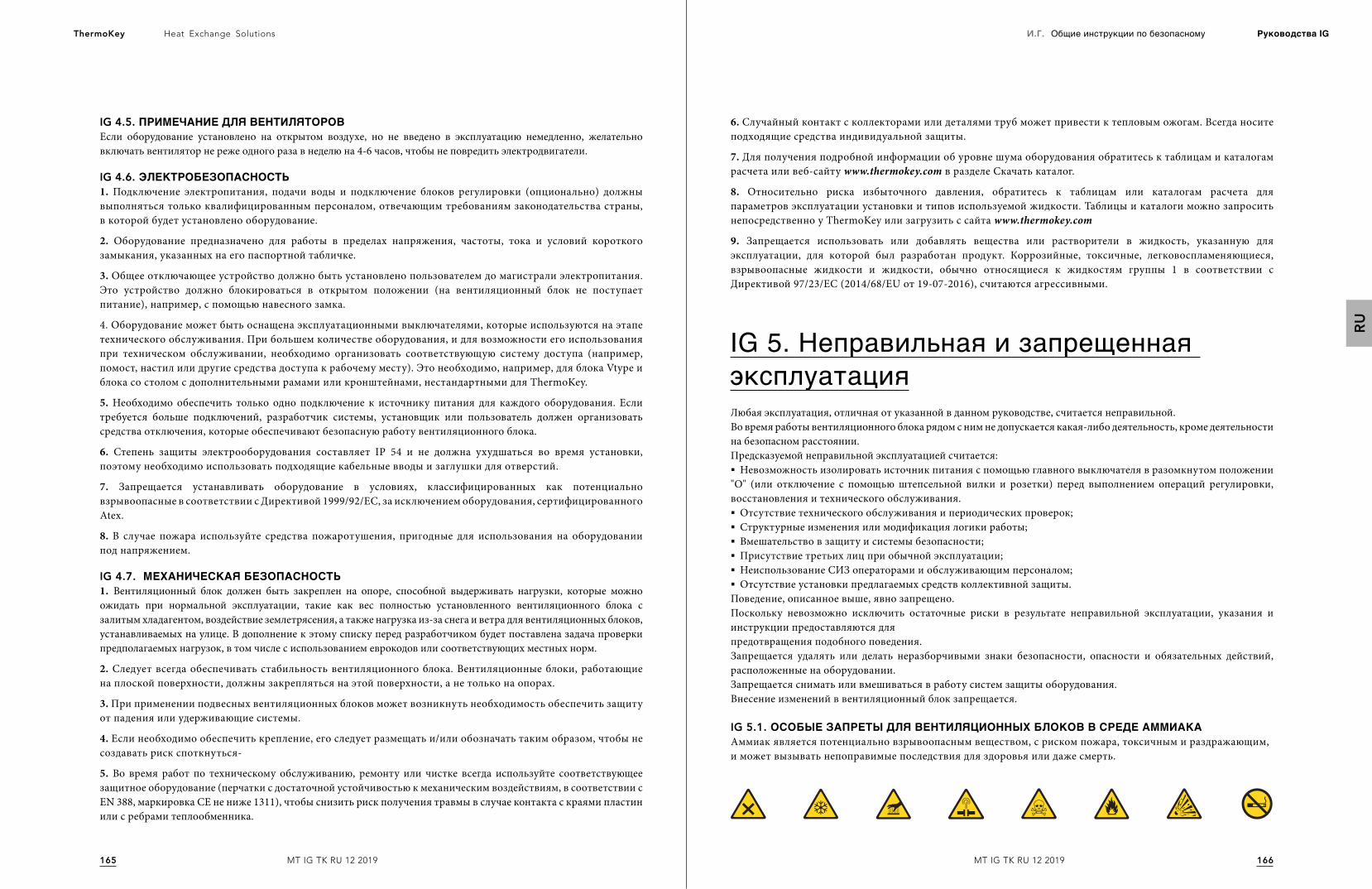
166165
Heat Exchange SolutionsThermoKey И.Г. Общие инструкции по безопасному Руководства IG
MT IG TK RU 12 2019MT IG TK RU 12 2019
RU
IG 4.5. ПРИМЕЧАНИЕДЛЯВЕНТИЛЯТОРОВЕсли оборудование установлено на открытом воздухе, но не введено в эксплуатацию немедленно, желательно включать вентилятор не реже одного раза в неделю на 4-6 часов, чтобы не повредить электродвигатели.
IG 4.6. ЭЛЕКТРОБЕЗОПАСНОСТЬ1. Подключение электропитания, подачи воды и подключение блоков регулировки (опционально) должны выполняться только квалифицированным персоналом, отвечающим требованиям законодательства страны, в которой будет установлено оборудование.
2. Оборудование предназначено для работы в пределах напряжения, частоты, тока и условий короткого замыкания, указанных на его паспортной табличке.
3. Общее отключающее устройство должно быть установлено пользователем до магистрали электропитания. Это устройство должно блокироваться в открытом положении (на вентиляционный блок не поступает питание), например, с помощью навесного замка.
4. Оборудование может быть оснащена эксплуатационными выключателями, которые используются на этапе технического обслуживания. При большем количестве оборудования, и для возможности его использования при техническом обслуживании, необходимо организовать соответствующую систему доступа (например, помост, настил или другие средства доступа к рабочему месту). Это необходимо, например, для блока Vtype и блока со столом с дополнительными рамами или кронштейнами, нестандартными для ThermoKey.
5. Необходимо обеспечить только одно подключение к источнику питания для каждого оборудования. Если требуется больше подключений, разработчик системы, установщик или пользователь должен организовать средства отключения, которые обеспечивают безопасную работу вентиляционного блока.
6. Степень защиты электрооборудования составляет IP 54 и не должна ухудшаться во время установки, поэтому необходимо использовать подходящие кабельные вводы и заглушки для отверстий.
7. Запрещается устанавливать оборудование в условиях, классифицированных как потенциально взрывоопасные в соответствии с Директивой 1999/92/EC, за исключением оборудования, сертифицированного Atex.
8. В случае пожара используйте средства пожаротушения, пригодные для использования на оборудовании под напряжением.
IG 4.7. МЕХАНИЧЕСКАЯБЕЗОПАСНОСТЬ1. Вентиляционный блок должен быть закреплен на опоре, способной выдерживать нагрузки, которые можно ожидать при нормальной эксплуатации, такие как вес полностью установленного вентиляционного блока с залитым хладагентом, воздействие землетрясения, а также нагрузка из-за снега и ветра для вентиляционных блоков, устанавливаемых на улице. В дополнение к этому списку перед разработчиком будет поставлена задача проверки предполагаемых нагрузок, в том числе с использованием еврокодов или соответствующих местных норм.
2. Следует всегда обеспечивать стабильность вентиляционного блока. Вентиляционные блоки, работающие на плоской поверхности, должны закрепляться на этой поверхности, а не только на опорах.
3. При применении подвесных вентиляционных блоков может возникнуть необходимость обеспечить защиту от падения или удерживающие системы.
4. Если необходимо обеспечить крепление, его следует размещать и/или обозначать таким образом, чтобы не создавать риск споткнуться-
5. Во время работ по техническому обслуживанию, ремонту или чистке всегда используйте соответствующее защитное оборудование (перчатки с достаточной устойчивостью к механическим воздействиям, в соответствии с EN 388, маркировка CE не ниже 1311), чтобы снизить риск получения травмы в случае контакта с краями пластин или с ребрами теплообменника.
IG 5. Неправильная и запрещенная эксплуатацияЛюбая эксплуатация, отличная от указанной в данном руководстве, считается неправильной.Во время работы вентиляционного блока рядом с ним не допускается какая-либо деятельность, кроме деятельности на безопасном расстоянии.Предсказуемой неправильной эксплуатацией считается:§ Невозможность изолировать источник питания с помощью главного выключателя в разомкнутом положении
"O" (или отключение с помощью штепсельной вилки и розетки) перед выполнением операций регулировки, восстановления и технического обслуживания.§ Отсутствие технического обслуживания и периодических проверок;§ Структурные изменения или модификация логики работы;§ Вмешательство в защиту и системы безопасности;§ Присутствие третьих лиц при обычной эксплуатации;§ Неиспользование СИЗ операторами и обслуживающим персоналом;§ Отсутствие установки предлагаемых средств коллективной защиты.
Поведение, описанное выше, явно запрещено.Поскольку невозможно исключить остаточные риски в результате неправильной эксплуатации, указания и инструкции предоставляются дляпредотвращения подобного поведения.Запрещается удалять или делать неразборчивыми знаки безопасности, опасности и обязательных действий, расположенные на оборудовании.Запрещается снимать или вмешиваться в работу систем защиты оборудования.Внесение изменений в вентиляционный блок запрещается.
IG 5.1. ОСОБЫЕЗАПРЕТЫДЛЯВЕНТИЛЯЦИОННЫХБЛОКОВВСРЕДЕАММИАКААммиак является потенциально взрывоопасным веществом, с риском пожара, токсичным и раздражающим, и может вызывать непоправимые последствия для здоровья или даже смерть.
6. Случайный контакт с коллекторами или деталями труб может привести к тепловым ожогам. Всегда носите подходящие средства индивидуальной защиты.
7. Для получения подробной информации об уровне шума оборудования обратитесь к таблицам и каталогам расчета или веб-сайту www.thermokey.com в разделе Скачать каталог.
8. Относительно риска избыточного давления, обратитесь к таблицам или каталогам расчета для параметров эксплуатации установки и типов используемой жидкости. Таблицы и каталоги можно запросить непосредственно у ThermoKey или загрузить с сайта www.thermokey.com
9. Запрещается использовать или добавлять вещества или растворители в жидкость, указанную для эксплуатации, для которой был разработан продукт. Коррозийные, токсичные, легковоспламеняющиеся, взрывоопасные жидкости и жидкости, обычно относящиеся к жидкостям группы 1 в соответствии с Директивой 97/23/EC (2014/68/EU от 19-07-2016), считаются агрессивными.
168167
Heat Exchange SolutionsThermoKey И.Г. Общие инструкции по безопасному Руководства IG
MT IG TK RU 12 2019MT IG TK RU 12 2019
RU
IG 6. Общие остаточные рискиIG6.1.СРЕДСТВАИНДИВИДУАЛЬНОЙЗАЩИТЫИОПАСНОСТИОстаточные риски делятся на общие и специфические. Общие остаточные риски - это те риски, которые могут быть отнесены к каждому вентиляционному блоку, независимо от модели или назначения, но которые определяются лишь на основе технологий и конструктивных решений. Общие риски содержатся в настоящей части руководства.Специфические риски свойственны каждому семейству вентиляционных блоков, модели или даже отдельному образцу. Специфические риски указаны в специальной документации вентиляционного блока и не обязательно в руководстве.
1. На оборудовании имеются риски, которые не были полностью устранены с точки зрения проектирования или после установки адекватных средств защиты.
2. В дополнение к положениям данного руководства и технической документации вентиляционного блока в целом пользователь обязан принять организационные меры, которые дополнительно снижают остаточные риски, включая защитные устройства, как индивидуальные (СИЗ), так и коллективные (СКЗ) для персонала, работающего с вентиляционным блоком.
3. 3. На этапах установки оборудования следует предусмотреть достаточно места для ограничения этих рисков. Чтобы соблюсти эти условия, коридоры и зоны, окружающие оборудование, всегда должны:
- быть свободными от препятствий (например, лестниц, инструментов, контейнеров, ящиков);- быть чистыми и сухими;- быть хорошо освещенными при необходимости.
РЕШЕНИЕ
ЭЛЕКТРОТОКОМИ
ОЖОГИ
ПОРАЖЕНИЕ
Оператор (в особых ситуациях или во время технического обслуживания) намеренно или непреднамеренно касается горячей или замерзшей поверхности.
Используйте изолирующие перчатки и/или подождите, пока поверхности остынут/нагреются
Контакт с электрическими деталями во время технического обслуживания.
Операции по техническому обслуживанию должны, насколько это возможно, выполняться, когда на оборудование не подается напряжение, и должны выполняться квалифицированными, обученными и уполномоченными операторами, оснащенными соответствующими СИЗ и изолированными инструментами.
Оператор на этапах эксплуатации и очистки может соприкоснуться с острыми ребрами теплообменников.
Оператор должен быть оснащен соответствующими СИЗ..РЕШЕНИЕ
БЛОКТЕПЛООБМЕНИКАСОСТРЫМИКРАЯМИ
ОПИСАНИЕОПАСНОЙСИТУАЦИИОПАСНОСТЬ
Ответственность за выявление и выбор типа и категории адекватных и уместных СИЗ ложитсяна клиента.Используемые СИЗ должен соответствовать директивам продукции и иметь маркировку CE (для европейского рынка
ФАЗАОПИСАНИЯ
ТРАНСПОРТИРОВКА
ИПЕРЕМЕЩЕНИЕ
РАСПАКОВКАИМОНТАЖ
ОБЫЧНАЯЭКСПЛУАТАЦИЯ
РЕГУЛИРОВКА
ОЧИСТКА
ТЕХНИЧЕСКОЕ
ОБСЛУЖИВАНИЕ
РАЗБОРКА
УТИЛИЗАЦИЯ
Относится к переносу оборудования из одного места в другое с использованием специальных средств.
Предусматривает передачу оборудования на и из транспортных средств, используемых для перевозки, а также перемещения внутри зданий.
Заключается в удалении всех материалов, используемых для упаковки оборудования.
Предусматривает все сборочные операции, которые изначально призваны подготовить оборудование к отладке.
Эксплуатация, для которой предназначено оборудование (или которая считается нормальным использованием) в отношении его проекта, конструкции и функции.
Обеспечивают регулировку, настройку и калибровку всех устройств, которые должны быть адаптированы к нормальным условиям эксплуатации.
Заключается в удалении пыли, масла и различных остатков, которые могут нарушить правильное функционирование и эксплуатацию оборудования, а также быть опасными для здоровья/безопасности оператора.
Заключается в периодической проверке частей оборудования, которые могут быть изношены или должны быть заменены.
Заключается в полной или частичной разборке оборудования для любых нужд.
Заключается в окончательном демонтаже всех частей оборудования, появившихся в результате окончательной операции по демонтажу, с тем чтобы обеспечить возможность повторного использования или раздельного сбора компонентов в соответствии с процедурами, предусмотренными действующими правилами.
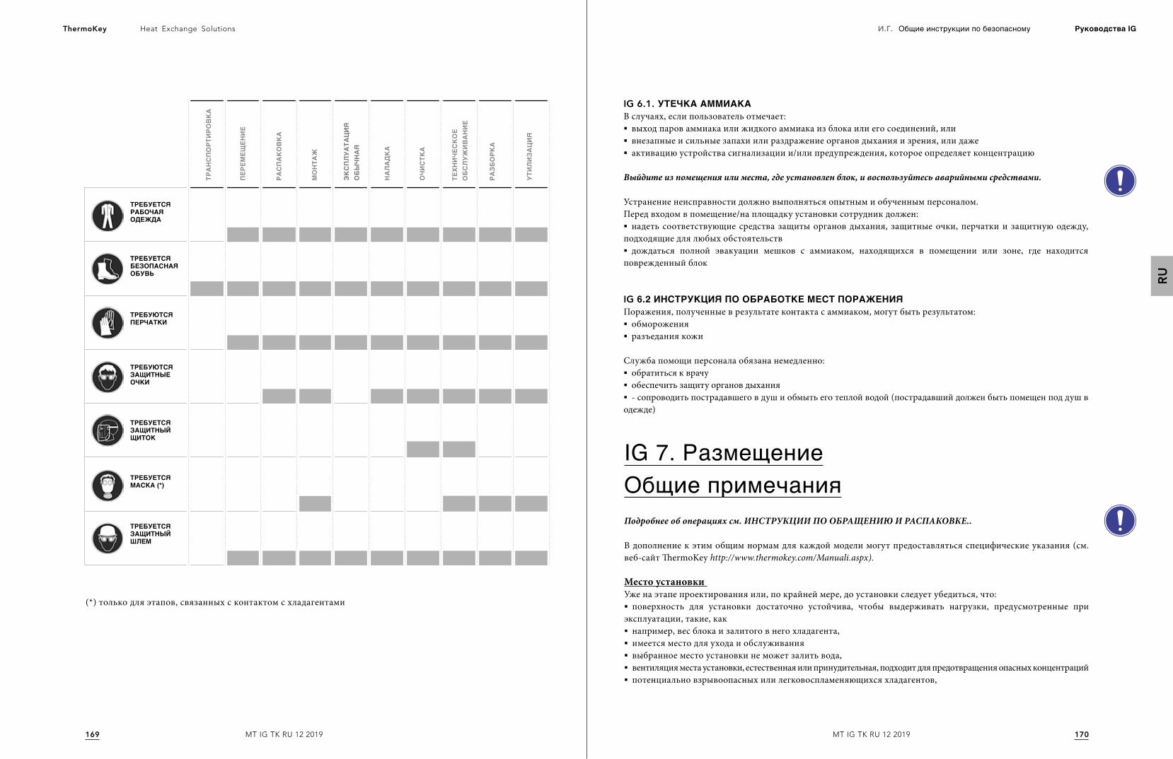
170169
Heat Exchange SolutionsThermoKey И.Г. Общие инструкции по безопасному Руководства IG
MT IG TK RU 12 2019MT IG TK RU 12 2019
RU
ТРЕБУЕТСЯРАБОЧАЯОДЕЖДА
ТРЕБУЕТСЯЗАЩИТНЫЙЩИТОК
ТРЕБУЕТСЯЗАЩИТНЫЙШЛЕМ
ТРЕБУЮТСЯПЕРЧАТКИ
ТРЕБУЕТСЯБЕЗОПАСНАЯОБУВЬ
ТРЕБУЕТСЯМАСКА(*)
ТРЕБУЮТСЯЗАЩИТНЫЕОЧКИ
ТРАНСПОРТ
ИРО
ВКА
ПЕР
ЕМЕЩ
ЕНИЕ
РАСПАКОВКА
МОНТА
Ж
НАЛАДКА
ОЧИ
СТК
А
ТЕХН
ИЧЕ
СКОЕ
ОБСЛУЖ
ИВАНИЕ
РАЗБ
ОРК
А
УТИЛИЗА
ЦИЯ
ЭКСПЛУА
ТАЦИЯ
ОБЫЧН
АЯ
(*) только для этапов, связанных с контактом с хладагентами
IG 6.1. УТЕЧКААММИАКАВ случаях, если пользователь отмечает:§ выход паров аммиака или жидкого аммиака из блока или его соединений, или§ внезапные и сильные запахи или раздражение органов дыхания и зрения, или даже§ активацию устройства сигнализации и/или предупреждения, которое определяет концентрацию
Выйдите из помещения или места, где установлен блок, и воспользуйтесь аварийными средствами.
Устранение неисправности должно выполняться опытным и обученным персоналом.Перед входом в помещение/на площадку установки сотрудник должен:§ надеть соответствующие средства защиты органов дыхания, защитные очки, перчатки и защитную одежду,
подходящие для любых обстоятельств§ дождаться полной эвакуации мешков с аммиаком, находящихся в помещении или зоне, где находится
поврежденный блок
IG 6.2ИНСТРУКЦИЯПООБРАБОТКЕМЕСТПОРАЖЕНИЯПоражения, полученные в результате контакта с аммиаком, могут быть результатом: § обморожения§ разъедания кожи
Служба помощи персонала обязана немедленно:§ обратиться к врачу§ обеспечить защиту органов дыхания§ - сопроводить пострадавшего в душ и обмыть его теплой водой (пострадавший должен быть помещен под душ в
одежде)
IG 7. РазмещениеОбщие примечанияПодробнее об операциях см. ИНСТРУКЦИИ ПО ОБРАЩЕНИЮ И РАСПАКОВКЕ..
В дополнение к этим общим нормам для каждой модели могут предоставляться специфические указания (см. веб-сайт ThermoKey http://www.thermokey.com/Manuali.aspx).
Место установки Уже на этапе проектирования или, по крайней мере, до установки следует убедиться, что:§ поверхность для установки достаточно устойчива, чтобы выдерживать нагрузки, предусмотренные при
эксплуатации, такие, как§ например, вес блока и залитого в него хладагента,§ имеется место для ухода и обслуживания§ выбранное место установки не может залить вода,§ вентиляция места установки, естественная или принудительная, подходит для предотвращения опасных концентраций§ потенциально взрывоопасных или легковоспламеняющихся хладагентов,
172171
Heat Exchange SolutionsThermoKey И.Г. Общие инструкции по безопасному Руководства IG
MT IG TK RU 12 2019MT IG TK RU 12 2019
RU
§ локальная температура блока во время фаз, в течение которых он не работает, не должна превышать 50°C;§ антивибрационные опоры и гибкие рукава на гидравлических линиях могут использоваться для ограничения
максимального распространения вибраций через твердые тела,§ адекватный уровень шума.
При установке внутри помещений также убедитесь, что помещение для установки должно соответствовать положениямEN 378-3 и другим техническим и юридическим спецификациям, действующим на месте установки. Для установок вне зданий дополнительно проверьте, чтобы§ положение блока находилось на уровне выше средней высоты снега,§ поверхность для установки была достаточно устойчива, чтобы выдерживать нагрузки, предусмотренные
при обычной эксплуатации, такие, как вес блока и залитого хладагента, и случайные нагрузки, такие как снег, ветер и аналогичные согласно EN 1991-5.
Подготовьте место и средства, необходимые для установки.
Особое внимание должно быть уделено проверке опасности гальванической коррозии, и, в частности, разработчик/установщик несет ответственность за обеспечение системы защиты от нее.
Следует предусмотреть (за это отвечает установщик/проектировщик) возможные внешние вибрации, например, вблизи дорог, вблизи аэропортов и т.д.
Мы рекомендуем установить амортизаторы у основания конструкции: обратитесь в каталог или на сайт. www.thermokey.com в разделе скачивания каталога.Для оценки силовых напряжений рекомендуется обратиться к EN 1991-6.
Использование антивибрационных систем может изменять условия сопротивления нагрузкам вентиляционных блоков (в частности, от ветра и определенных вибраций).
Для определения размеров труб, особенно для аммиака и хладагентов группы 1, рекомендуется применять EN 1998-6
При выборе места установки необходимо учитывать ряд возможных рисков, которые могут возникнуть как во время установки, так и на последующих этапах обычной эксплуатации и во время демонтажа. Ответственность за оценку рисков, имеющихся на месте установки, несет проектировщик, установщик и/или пользователь. Неисчерпывающий, но ориентировочный список приведен ниже.
Зона вблизи или ниже вентиляционных блоков может быть скользкой: следует должным образом сообщить о риске.
Крепеж и вообще все выступающие конструкции вентиляционного блока могут создавать опасность спотыкания.
Для подвесных вентиляционных блоков и для больших вентиляционных блоков существует риск удара головой по причине высоты установки.
При установке на высоте (на террасных крышах, опорных конструкциях или аналогичных средствах, превышающих 2 м высоты от поверхности для ходьбы), существует опасность падения сверху, которая должна быть уменьшена с помощью средств коллективной защиты.
Использование аммиака и хладагентов группы 1 может привести к взрыву из-за создания взрывоопасной атмосферы. Все необходимые меры предосторожности должны быть приняты на этапе проектирования, чтобы избежать этой проблемы.
IG 7.1. МИНИМАЛЬНЫЕТЕХНИЧЕСКИЕРАССТОЯНИЯМинимальные технические расстояния могут быть разными, для их определения следует обратиться к конкретным указаниямв технической документации. Если таковые отсутствуют, немедленно обратитесь к ThermoKey.
IG 7.2. ИНСПЕКТИРОВАНИЕНАМОМЕНТПОСТАВКИПроверьте соответствие подтверждения заказа с данными, указанными на паспортной табличке и проверьте электрические параметры относительно требуемых. Не продолжайте установку, если имеются какие-либо несоответствия параметров.
Если на вентиляционном блоке обнаружен дефект во время распаковки и/или установки, немедленно сообщите об этом производителю и не выполняйте следующие шаги без его явного разрешения
IG 7.3. РАСПАКОВКАБЛОКАУпаковка может быть разного типа, поэтому необходимо обратиться к конкретным указаниям, приведенным в технической документации. Если таковые отсутствуют, немедленно запросите их у ThermoKey и не выполняйте каких-либо операций по распаковке.
IG 7.4 РАЗМЕЩЕНИЕЗапрещается останавливаться и проходить в зоне работ любой грузоподъемной машины.
Обязательно снимайте защитную пленку с обтекателя, если таковая имеется, после установки.
При установке, требующей работ на высоте или при наличии риска падения, не используйте лестницы, а следуйте местным правилам безопасности, приведенным в разделе "Работы на высоте".
Работы на высоте могут выполняться только в том случае, если погодные условия не угрожают безопасности работников.
174173
Heat Exchange SolutionsThermoKey И.Г. Общие инструкции по безопасному Руководства IG
MT IG TK RU 12 2019MT IG TK RU 12 2019
RU
IG 8. УстановкаУстановка - это этап, следующий за размещением вентиляционного блока, на котором выполняются операции по фиксации его к опоре, размещаются крепежные элементы, выполняется повторная сборка частей, которые в конечном итоге демонтируются для перемещения.
Установка должна выполняться в соответствии с инструкциями, приведенными в руководстве, и в соответствии с указаниями EN 378-3.
Механический подъем вентиляционного блока является обязанностью установщика. Вентиляционный блок снабжен отверстиями для фиксации. Если размеры отверстий недостаточны, не увеличивайте их без разрешения ThermoKey.
Диаметры отверстий для фиксации являются результатом статических расчетов изготовителя; фиксирующие элементы должны принимать во внимание диаметр отверстий.Фиксирующие элементы должны быть оснащены всеми подходящими средствами для предотвращения их ослабления.
Чтобы определить размеры анкерного крепления или фиксирующих устройств вентиляционных блоков, используйте эталонные стандарты ETAG и обратитесь к техническим каталогам, доступным на веб-сайте. www.thermokey.com в разделе скачивания каталога.
Крепления можно использовать для улучшения устойчивости к ветровой нагрузке блока, установленного вне помещения. Выбор и размер крепежа определяет установщик.
IG 9. Подключение охлаждающих и водных систем Категорически запрещается адаптировать положение коллекторов к впускной линии, которое не должно смещаться из исходного положения.
§ При подготовке соединений входных/выходных труб обязательно проверьте индикацию направления движения хладагента, нанесенную на муфтах или фланцах.§ Мы рекомендуем установить запорные клапаны на входе, чтобы облегчить операции по техническому
обслуживанию. Если установка указанных клапанов сопряжена с риском, то установщик обязан предоставить соответствующие решения для контуров.§ Для конденсаторов и сухих охладителей, оборудованных адиабатическими системами, следует обязательно, если
температура окружающей среды ниже 0°C, слить воду из системы подачи, чтобы предотвратить образование льда.§ В случае соединений для хладагента и воды обязательно соблюдайте диаметры подготовленных соединений.
Любые изменения должны быть предварительно согласованы с отделом обслуживания клиентов ThermoKey, иначе последняя не несет какую-либо ответственность, связанную с нанесением ущерба людям, животным или имуществу, за рабочие параметры хуже заявленных и указанных в условиях гарантии.
IG 9.1. ГИДРАВЛИЧЕСКИЕСОЕДИНЕНИЯГидравлические соединения должны выполняться в соответствии с национальными или местными правилами; трубы могут быть изготовлены из стали, оцинкованной стали или ПВХ. Размеры труб должны быть тщательно рассчитаны в соответствии с номинальным расходом хладагента, давлением, потерями нагрузки гидравлического контура и рабочие температуры. Все гидравлические соединения должны быть изолированы с использованием материала с закрытыми порами соответствующей толщины.
IG 9.2. МОНТАЖТРУБ§ Правильно закрепите все трубы, избегая механических повреждений, следуя правильной процедуре сборки и
указаниям, приведенным в разделе "Технические характеристики" на странице загрузки сайта. www.thermokey.com§ Во время сборки поддерживайте трубы так, чтобы не повредить системы фиксации.§ Если установка происходит в местах, где разрешен транзит персонала, размещайте трубы таким образом,
чтобы они не были препятствием для этого транзита, и убедитесь, что трубы соединены с фитингами, которые прочно прикреплены.§ Используйте устройства для фиксации, подходящие для веса труб, чтобы весь вес труб не приходился на
соединения, вызывая их поломку и отсоединение от блока.
В вентиляционных блоках, в которых используется аммиак или взрывоопасные или легковоспламеняющиеся жидкости, неправильная установка труб может привести к риску утечки хладагента.
IG 9.3. СВАРКА§ В случае соединения с помощью сварки, во избежание утечки, выполняйте сварочные работы с должной
точностью и вниманием;§ избегайте перегрева во время сварки (опасность изменения размеров);§ Используйте защитный газ во время сварки (избегайте чрезмерного образования налета):§ сварочные работы на деталях, находящихся под давлением, могут привести к пожару или взрыву;§ выполняйте сварочные работы, только если блок находится не под нагрузкой и давлением;§ убедитесь, что нагрузки и вибрации не воздействуют на блок;§ при сварке соединений запрещается направлять пламя на устройство и/или на любое установленное
электрическое оборудование.
IG 10. Электрические подключения Электрические соединения должны выполняться в соответствии с настоящим руководством, а также с электрическими схемами, приведенными в инструкциях и технических данных, а также согласно правилам, касающимся электрических систем, действующим в стране, где установлен блок.
Необходимо обязательно подключить заземление к оборудованию.
§ Операции по электрическому подключению должны выполняться квалифицированным персоналом, соответствующим необходимым техническим требованиям, определенным страной, в которой устанавливается блок.§ Обязательно убедитесь, что напряжение сети соответствует значению, указанному на паспортной табличке.§ Выбор и размеры кабеля электропитания вентиляционного блока являются обязанностью проектировщика/
установщика.
176175
Heat Exchange SolutionsThermoKey И.Г. Общие инструкции по безопасному Руководства IG
MT IG TK RU 12 2019MT IG TK RU 12 2019
RU
§ При прокладке силового кабеля рекомендуется использовать кабельные желоба или трубы, которые механически защищают кабель. Категорически не рекомендуется установка на пол без фиксации.§ Обязательно используйте силовые кабели, тип и минимальное сечение которых соответствуют EN 60204-1 и,
возможно, техническим стандартам, действующим в стране установки.§ Допустимые мощности и характеристики для определения параметров магистрального электрического кабеля
указаны на заводской табличке и/или в технических каталогах.§ Необходимо обязательно снабдить систему электропитания устройством для защиты от сверхтоков, таким как
магнитотермический выключатель, и от перенапряжений.§ Электрический кабель должен прокладываться в щитах и электрических коробках вентиляционного блока
снизу или, в любом случае, таким образом, чтобы снизить риск проникновения воды внутрь. При этом, всегда необходимо использовать кабельные вводы. - Защита от непрямых электрических контактов происходит путем заземления металлической конструкции вентиляционного блока и согласования с автоматическими выключателями для распределительных систем TT и TN-S.§ В непосредственной близости от клемм электропитания на электрической панели заземляющий провод
(желтый/зеленый) должен быть длиннее других проводников, чтобы в случае сильной тянущей нагрузки на кабель заземляющий проводник отсоединялся последним от зажимов. - В трехфазных и однофазных моделях линия электропитания должна быть подключена к общему распределительному щиту.§ Если несколько вентиляторов установлены последовательно, они должны быть включены в эквипотенциальную
систему: соединение должно быть выполнено с помощью клеммы, отмеченной символом на боковой стороне коллектора. Сечение этого проводника (желто-зеленого цвета) должно быть равно или превышать максимальное сечение шнура питания. - Для электрических соединений вентиляторов, где отсутствует распределительный щит электропитания, обязательно обратитесь к электрической схеме, приведенной в коробке питания вентилятора. Рекомендуется подключать термоконтакты TK последовательно для управления сигнализацией.§ Если блок оборудован системой регулировки (регуляторы оборотов или электронные вентиляторы ЕС),
перед подключением агрегата к распределительной сети необходимо гарантировать соответствие EN61000-3-2 и EN61000-3-12. - Используйте только регуляторы оборотов с инвертором, поставляемые ThermoKey. Использование других преобразователей должен подтвердить технический отдел ThermoKey.
IG 11. ХладагентыВся информация, содержащаяся в настоящем параграфе, носит общий характер и не заменяет информацию, содержащуюся в технических паспортах и паспортах безопасности используемого хладагента.
Всегда обращайтесь к информации, содержащейся в паспортах безопасности хладагента.
IG 11.1 АММИАКВКАЧЕСТВЕХЛАДАГЕНТА§ Аммиак токсичен для дыхательной системы,§ длительное или интенсивное воздействие паров аммиака может привести к изъязвлению конъюнктивы§ и роговицы, отеку глотки, бронхоспазму, отеку легких и остановке дыхания.§ аммиак оказывает сильное раздражающее действие на слизистые оболочки глаза и, при наличии влаги, на кожу,§ брызги жидкого аммиака могут вызвать холодные ожоги или ожоги из-за его едкого воздействия,§ аммиак может быть опасным для водной среды, особенно для рыб.
IG 11.2 УКАЗАНИЯПОБЕЗОПАСНОСТИИПРЕДОСТЕРЕЖЕНИЯВся информация об опасности и предостережения приведены в постановлении ЕС 1272/2008.Ниже приводятся лишь несколько примеров
IG 12. Инспектируемые вентиляционные блоки Инспектируемые вентиляционные блоки позволяют получить доступ к отсеку вентилятора без полного извлечения самого вентилятора. Эта функция, в качестве опции, требует дополнительных технических мер, описанных в разделе "Технические характеристики" в разделе скачиваний сайта www.thermokey.com
Для инспектируемых вентиляционных блоков, в которых ответственность за установку дополнительного оборудования (например, системы электрической блокировки и т.д.) несет пользователь, безопасность и соответствие вентиляционного блока закону гарантируется только и исключительно при полном завершении установки, как указано ThermoKey.
ОпасностьH221: Пожароопасный газ.H331: Токсичен при вдыхании.H314: Вызывает серьезные ожоги кожи и повреждения глаз.H400: Очень токсичен для водных организмов.EUH071: Разъедает дыхательные пути
ПредостереженияP210: Хранить вдали от источников тепла/искрообразования/нагрева/перегрева. - Не курить.P280: Носить защитные перчатки/защитную одежду/средства защиты глаз/лица.P260: Не вдыхать пары.P273: Не рассеивать в окружающей среде.P377: В случае пожара из-за утечки газа не тушите, если утечка не может быть остановлена безопасности.P381: Устраните все источники возгорания.P303 + P361 + P353 +315: В случае контакта с кожей (или волосами): немедленно снимитезагрязненную одежду. Промойте пораженное место/примите душ. Немедленно обратитесь к врачу.P304 + P340 + P315: В случае вдыхания: доставить пострадавшего на открытый воздух и держать его в покое вположении, которое способствует дыханию. Немедленно обратитесь к врачу.P305 + P351 + P338 + P315: В случае контакта с глазами: тщательно промывать в течение нескольких минут.Снимите контактные линзы, если это легко сделать. Продолжайте промывать. Немедленно обратитесь к врачу.
ThermoKey Spavia dell’Industria, 1 - 33061
Rivarotta di Rivignano Teor (UD) - Italy
T. +39 0432 772300F. +39 0432 779734