Elleec cttrriicaall IMMaacchhiinneess 7IVV t …bu.edu.eg/portal/uploads/Engineering,...
14
Electrical Machines IV – Code: CECE 437 – http://bu.edu.eg/staff/emadattwa3 1 Speed of Rotating Magnetic Field Referring to Fig. 7 during the time period (from no. 1 to no. 4), the current I x represents ¼ cycle. In this period of the current cycle, the rotating field rotates 90 o . So, for that 2-pole induction motor; one cycle of the current make one revolution of the field. But, for a 4-pole induction motor, two cycles of the current make one revolution of the field. What the relation between cycle of the current and number of revolution of the motor? Cycles of current = (P/2) Revolutions of field Cycles of current/sec = (P/2) × Revolutions of field/sec f = (P/2) × (N s /60)
Transcript of Elleec cttrriicaall IMMaacchhiinneess 7IVV t …bu.edu.eg/portal/uploads/Engineering,...
EElleeccttrriiccaall MMaacchhiinneess IIVV –– CCooddee:: CCEECCEE 443377 –– hhttttpp::////bbuu..eedduu..eegg//ssttaaffff//eemmaaddaattttwwaa33
1
Speed of Rotating Magnetic Field
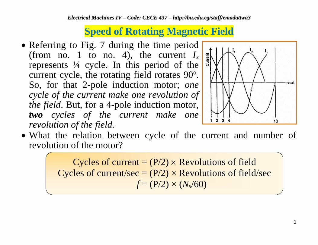
Referring to Fig. 7 during the time period (from no. 1 to no. 4), the current Ix represents ¼ cycle. In this period of the current cycle, the rotating field rotates 90o. So, for that 2-pole induction motor; one cycle of the current make one revolution of the field. But, for a 4-pole induction motor, two cycles of the current make one revolution of the field.
What the relation between cycle of the current and number of revolution of the motor?
Cycles of current = (P/2) Revolutions of field
Cycles of current/sec = (P/2) × Revolutions of field/sec
f = (P/2) × (Ns/60)
EElleeccttrriiccaall MMaacchhiinneess IIVV –– CCooddee:: CCEECCEE 443377 –– hhttttpp::////bbuu..eedduu..eegg//ssttaaffff//eemmaaddaattttwwaa33
2
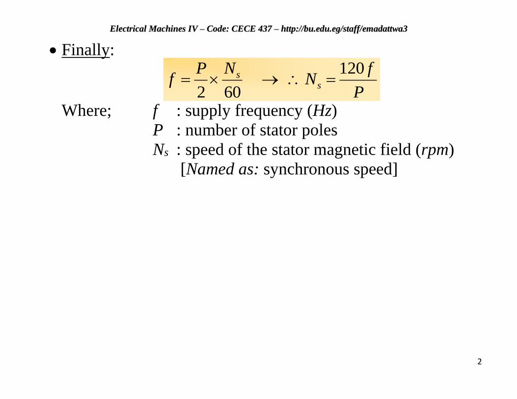
Finally:
P
fN
NPf s
s 120
602
Where; f : supply frequency (Hz)
P : number of stator poles
Ns : speed of the stator magnetic field (rpm)
[Named as: synchronous speed]
EElleeccttrriiccaall MMaacchhiinneess IIVV –– CCooddee:: CCEECCEE 443377 –– hhttttpp::////bbuu..eedduu..eegg//ssttaaffff//eemmaaddaattttwwaa33
3
Why the speed of the 3-phase induction motor is named as
a Synchronous Speed?
The speed of the rotating magnetic field of the stator in the 3-phase induction motor is the same as the speed of the alternator that is supplying power to the motor if the two machines (motor and alternator) have the same number of poles. Hence the magnetic flux in the stator is said to rotate at synchronous speed (Ns).
Watch Video: How does an Induction Motor work? (4:05 min)
For example, for a 6-pole, 50 Hz, 3-phase induction motor, Ns = 120 * 50/6 = 1000 rpm. It means that the flux rotates around the stator at a speed of 1000 rpm.
EElleeccttrriiccaall MMaacchhiinneess IIVV –– CCooddee:: CCEECCEE 443377 –– hhttttpp::////bbuu..eedduu..eegg//ssttaaffff//eemmaaddaattttwwaa33
4
How Can You Change Motor Direction of Rotation?
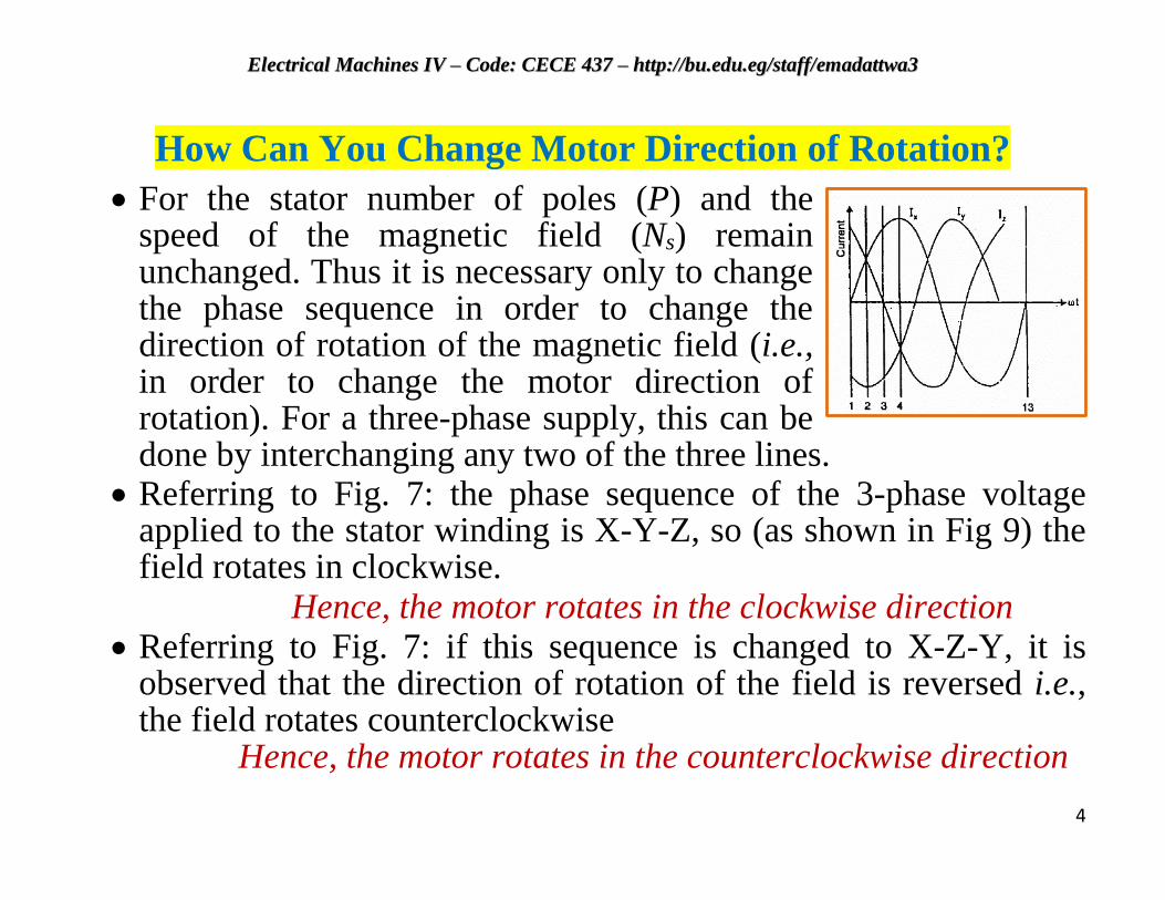
For the stator number of poles (P) and the speed of the magnetic field (Ns) remain unchanged. Thus it is necessary only to change the phase sequence in order to change the direction of rotation of the magnetic field (i.e., in order to change the motor direction of rotation). For a three-phase supply, this can be done by interchanging any two of the three lines.
Referring to Fig. 7: the phase sequence of the 3-phase voltage applied to the stator winding is X-Y-Z, so (as shown in Fig 9) the field rotates in clockwise.
Hence, the motor rotates in the clockwise direction Referring to Fig. 7: if this sequence is changed to X-Z-Y, it is
observed that the direction of rotation of the field is reversed i.e., the field rotates counterclockwise
Hence, the motor rotates in the counterclockwise direction
EElleeccttrriiccaall MMaacchhiinneess IIVV –– CCooddee:: CCEECCEE 443377 –– hhttttpp::////bbuu..eedduu..eegg//ssttaaffff//eemmaaddaattttwwaa33
5
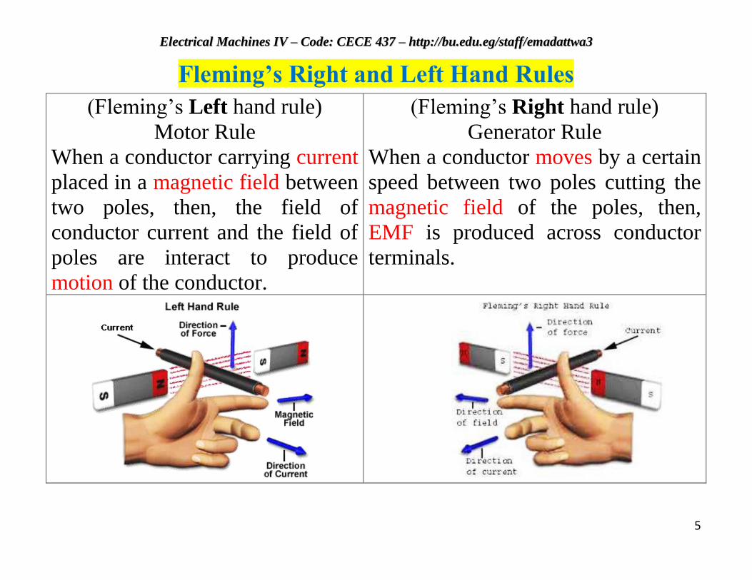
Fleming’s Right and Left Hand Rules
(Fleming’s Left hand rule)
Motor Rule
When a conductor carrying current
placed in a magnetic field between
two poles, then, the field of
conductor current and the field of
poles are interact to produce
motion of the conductor.
(Fleming’s Right hand rule)
Generator Rule
When a conductor moves by a certain
speed between two poles cutting the
magnetic field of the poles, then,
EMF is produced across conductor
terminals.
EElleeccttrriiccaall MMaacchhiinneess IIVV –– CCooddee:: CCEECCEE 443377 –– hhttttpp::////bbuu..eedduu..eegg//ssttaaffff//eemmaaddaattttwwaa33
6
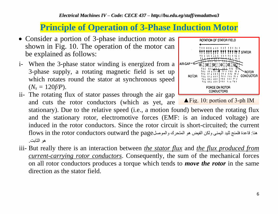
▲Fig. 10: portion of 3-ph IM
Principle of Operation of 3-Phase Induction Motor
Consider a portion of 3-phase induction motor as shown in Fig. 10. The operation of the motor can be explained as follows:
i- When the 3-phase stator winding is energized from a
3-phase supply, a rotating magnetic field is set up
which rotates round the stator at synchronous speed
(Ns = 120f/P).
ii- The rotating flux of stator passes through the air gap
and cuts the rotor conductors (which as yet, are
stationary). Due to the relative speed (i.e., a motion found) between the rotating flux
and the stationary rotor, electromotive forces (EMF: is an induced voltage) are
induced in the rotor conductors. Since the rotor circuit is short-circuited; the current
flows in the rotor conductors outward the page صل قاعدة فلمنج لليد اليمنى ولكن الفيض هو المتحرك والموهنا:
.هو الثابت
iii- But really there is an interaction between the stator flux and the flux produced from
current-carrying rotor conductors. Consequently, the sum of the mechanical forces
on all rotor conductors produces a torque which tends to move the rotor in the same
direction as the stator field.
EElleeccttrriiccaall MMaacchhiinneess IIVV –– CCooddee:: CCEECCEE 443377 –– hhttttpp::////bbuu..eedduu..eegg//ssttaaffff//eemmaaddaattttwwaa33
7
Slip
We have seen: the rotor rapidly accelerates in the direction of the
stator field.
In practice, the rotor can never reach the speed of the stator flux. If it
did, there would be no relative speed between the stator field and
rotor conductors, no induced rotor currents and, therefore, no torque
to drive the rotor. The friction and windage would immediately
cause the rotor to slow down.
Hence, the rotor speed (N) is always less than the stator field speed
(Ns). This difference in speed depends upon load on the motor.
EElleeccttrriiccaall MMaacchhiinneess IIVV –– CCooddee:: CCEECCEE 443377 –– hhttttpp::////bbuu..eedduu..eegg//ssttaaffff//eemmaaddaattttwwaa33
8
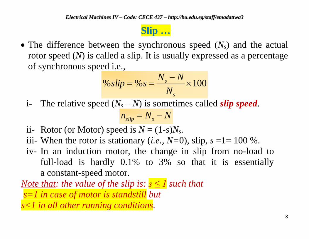
Slip …
The difference between the synchronous speed (Ns) and the actual
rotor speed (N) is called a slip. It is usually expressed as a percentage
of synchronous speed i.e.,
100%%
s
s
N
NNsslip
i- The relative speed (Ns – N) is sometimes called slip speed.
NNn sslip
ii- Rotor (or Motor) speed is N = (1-s)Ns.
iii- When the rotor is stationary (i.e., N=0), slip, s =1= 100 %.
iv- In an induction motor, the change in slip from no-load to
full-load is hardly 0.1% to 3% so that it is essentially
a constant-speed motor.
Note that: the value of the slip is: s ≤ 1 such that
s=1 in case of motor is standstill but
s<1 in all other running conditions.
EElleeccttrriiccaall MMaacchhiinneess IIVV –– CCooddee:: CCEECCEE 443377 –– hhttttpp::////bbuu..eedduu..eegg//ssttaaffff//eemmaaddaattttwwaa33
9
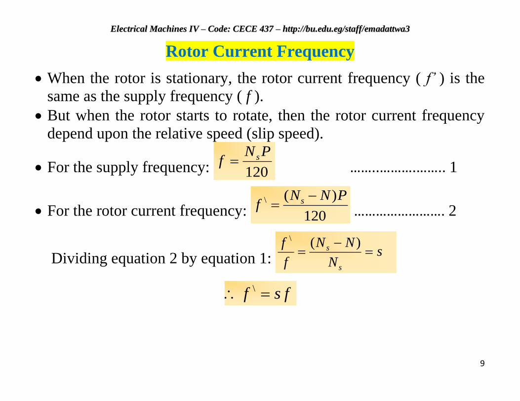
Rotor Current Frequency
When the rotor is stationary, the rotor current frequency ( f’ ) is the
same as the supply frequency ( f ).
But when the rotor starts to rotate, then the rotor current frequency
depend upon the relative speed (slip speed).
For the supply frequency: 120
PNf s ……..……….…….. 1
For the rotor current frequency: 120
)(\ PNNf s ……………………. 2
Dividing equation 2 by equation 1: s
N
NN
f
f
s
s
)(\
fsf \
EElleeccttrriiccaall MMaacchhiinneess IIVV –– CCooddee:: CCEECCEE 443377 –– hhttttpp::////bbuu..eedduu..eegg//ssttaaffff//eemmaaddaattttwwaa33
10
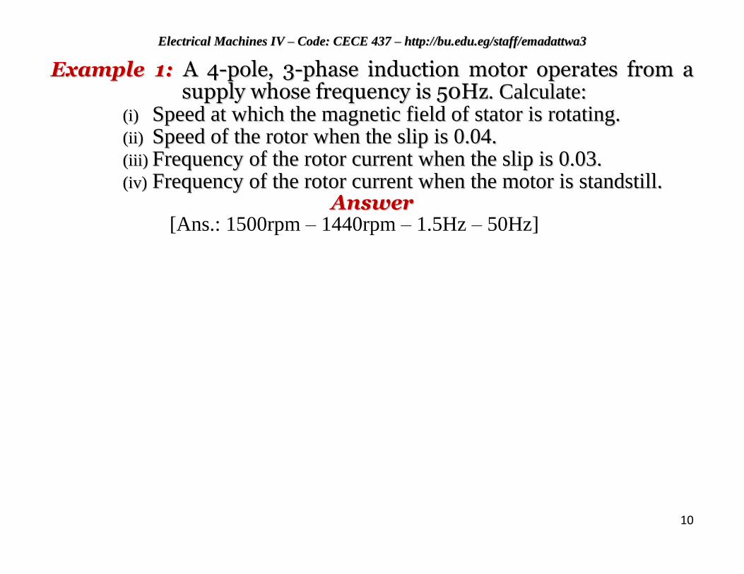
EExxaammppllee 11:: AA 44--ppoollee,, 33--pphhaassee iinndduuccttiioonn mmoottoorr ooppeerraatteess ffrroomm aa ssuuppppllyy wwhhoossee ffrreeqquueennccyy iiss 5500HHzz.. CCaallccuullaattee::
((ii)) SSppeeeedd aatt wwhhiicchh tthhee mmaaggnneettiicc ffiieelldd ooff ssttaattoorr iiss rroottaattiinngg.. ((iiii)) SSppeeeedd ooff tthhee rroottoorr wwhheenn tthhee sslliipp iiss 00..0044.. ((iiiiii)) FFrreeqquueennccyy ooff tthhee rroottoorr ccuurrrreenntt wwhheenn tthhee sslliipp iiss 00..0033.. ((iivv)) FFrreeqquueennccyy ooff tthhee rroottoorr ccuurrrreenntt wwhheenn tthhee mmoottoorr iiss ssttaannddssttiillll..
AAnnsswweerr [Ans.: 1500rpm – 1440rpm – 1.5Hz – 50Hz]
EElleeccttrriiccaall MMaacchhiinneess IIVV –– CCooddee:: CCEECCEE 443377 –– hhttttpp::////bbuu..eedduu..eegg//ssttaaffff//eemmaaddaattttwwaa33
11
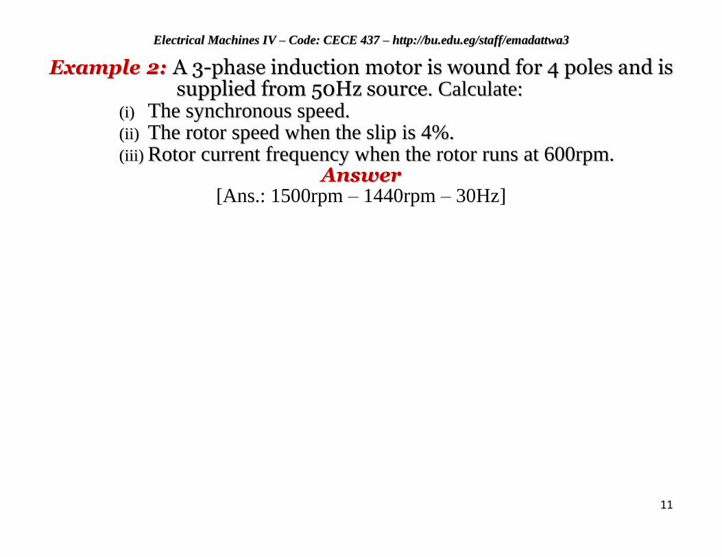
EExxaammppllee 22:: AA 33--pphhaassee iinndduuccttiioonn mmoottoorr iiss wwoouunndd ffoorr 44 ppoolleess aanndd iiss ssuupppplliieedd ffrroomm 5500HHzz ssoouurrccee.. CCaallccuullaattee::
((ii)) TThhee ssyynncchhrroonnoouuss ssppeeeedd.. ((iiii)) TThhee rroottoorr ssppeeeedd wwhheenn tthhee sslliipp iiss 44%%.. ((iiiiii)) RRoottoorr ccuurrrreenntt ffrreeqquueennccyy wwhheenn tthhee rroottoorr rruunnss aatt 660000rrppmm..
AAnnsswweerr [Ans.: 1500rpm – 1440rpm – 30Hz]
EElleeccttrriiccaall MMaacchhiinneess IIVV –– CCooddee:: CCEECCEE 443377 –– hhttttpp::////bbuu..eedduu..eegg//ssttaaffff//eemmaaddaattttwwaa33
12
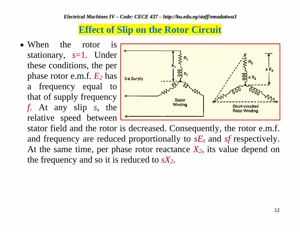
Effect of Slip on the Rotor Circuit
When the rotor is
stationary, s=1. Under
these conditions, the per
phase rotor e.m.f. E2 has
a frequency equal to
that of supply frequency
f. At any slip s, the
relative speed between
stator field and the rotor is decreased. Consequently, the rotor e.m.f.
and frequency are reduced proportionally to sEs and sf respectively.
At the same time, per phase rotor reactance X2, its value depend on
the frequency and so it is reduced to sX2.
EElleeccttrriiccaall MMaacchhiinneess IIVV –– CCooddee:: CCEECCEE 443377 –– hhttttpp::////bbuu..eedduu..eegg//ssttaaffff//eemmaaddaattttwwaa33
13
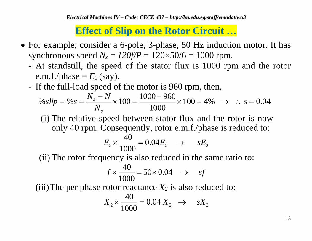
Effect of Slip on the Rotor Circuit …
For example; consider a 6-pole, 3-phase, 50 Hz induction motor. It has
synchronous speed Ns = 120f/P = 120×50/6 = 1000 rpm.
- At standstill, the speed of the stator flux is 1000 rpm and the rotor
e.m.f./phase = E2 (say).
- If the full-load speed of the motor is 960 rpm, then,
04.0%41001000
9601000100%%
s
N
NNsslip
s
s
(i) The relative speed between stator flux and the rotor is now only 40 rpm. Consequently, rotor e.m.f./phase is reduced to:
222 04.01000
40sEEE
(ii) The rotor frequency is also reduced in the same ratio to:
sff 04.0501000
40
(iii) The per phase rotor reactance X2 is also reduced to:
222 04.01000
40sXXX
EElleeccttrriiccaall MMaacchhiinneess IIVV –– CCooddee:: CCEECCEE 443377 –– hhttttpp::////bbuu..eedduu..eegg//ssttaaffff//eemmaaddaattttwwaa33
14
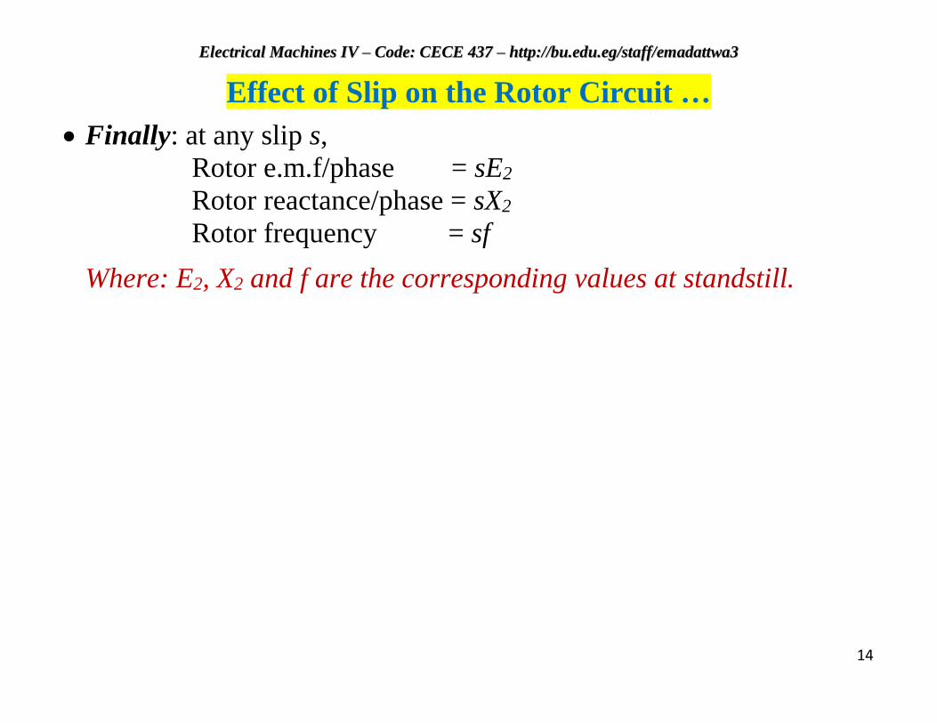
Effect of Slip on the Rotor Circuit …
Finally: at any slip s,
Rotor e.m.f/phase = sE2
Rotor reactance/phase = sX2
Rotor frequency = sf
Where: E2, X2 and f are the corresponding values at standstill.