DSE atex E - Endüstri Teknik · JAQUET AG, Thannerstrasse 15, CH 4009 Basel Änderungen : 05.04.04...
46
JAQUET CERTIFICATE M/YY 1/46 www.jaquet.com ATEX Certificate of the QM-System page 2 Elektromagnetic Sensors DSE... pages 3 .. 14 Ferrostat sensors DSF .. pages 15 .. 34 Ferrostat-differential sensors FTG 1088 .. pages 35 .. 40 Ferrostat-differential sensors FTG 1089 .. pages 41 .. 46 Ex – Sensors ATEX
Transcript of DSE atex E - Endüstri Teknik · JAQUET AG, Thannerstrasse 15, CH 4009 Basel Änderungen : 05.04.04...
JAQUETCERTIFICATE
M/YY1/46
ww
w.ja
quet
.com
ATEX Certificate of the QM-System page 2
Elektromagnetic Sensors DSE... pages 3 .. 14
Ferrostat sensors DSF .. pages 15 .. 34
Ferrostat-differential sensors FTG 1088 .. pages 35 .. 40
Ferrostat-differential sensors FTG 1089 .. pages 41 .. 46
Ex – Sensors ATEX
JAQUET AG, Thannerstrasse 15, CH 4009 Basel Änderungen : 05.04.04 1/12
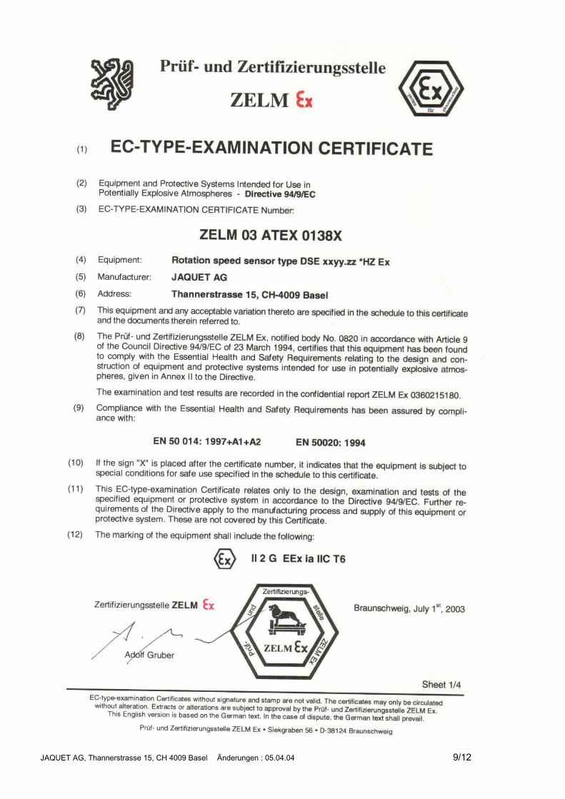
Electromagnetic SensorSeries DSEExplosion proof versions EEx
DSE _ _ _ _.21 ExDSE _ _ _ _.22 ExDSE _ _ _ _.23 Ex
ATEXOperating Instructions347E-64449valid beginning with serial no. 0103
GeneralFunction Sensors DSE xxxx.21/22/23 are used to convert rotational and linear movement into elec-
tronic signals and consist of an iron core and induction coil mounted in front of a perma-nent magnet, with an electronic limiting circuit for output voltage and output current. Thepole wheel rotating close to the sensor head affects the magnetic field and, according tothe laws of induction, generates a voltage in the coil which is proportional to the rate ofchange of magnetic flux in the iron core. The magnitude of the sensor voltage depends onthe distance between pole wheel/sensor and the dimensions of the poles. It is also more orless proportional to the rotational speed of the pole wheel. The electromagnetic sensorrequires no auxiliary power supply for signal generation.
Usage in an Eex explosionrisk environment
Please note the terms of the “EC-Type Examination Certificate”.Sensors of type DSE xxxx.21/ 22/ 23 xHZ Ex atex are certified as intrinsically safe II 2 GEEx ia IIC T6-T1 to be used in plant locations with Ex-Zone 1 (Group II) with EC-TypeExamination Certificate no. ZELM 03 ATEX 0138X.A copy of the EC-Type Examination Certificate is an integral part of these OperatingInstructions.
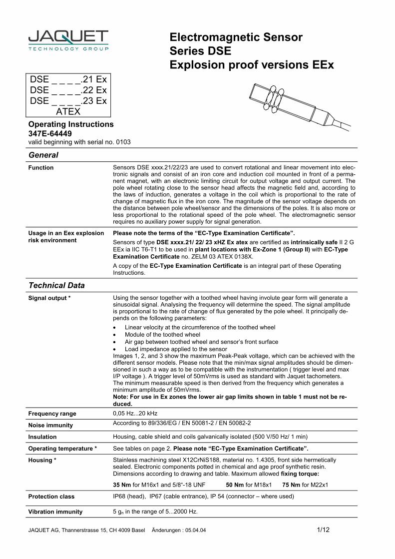
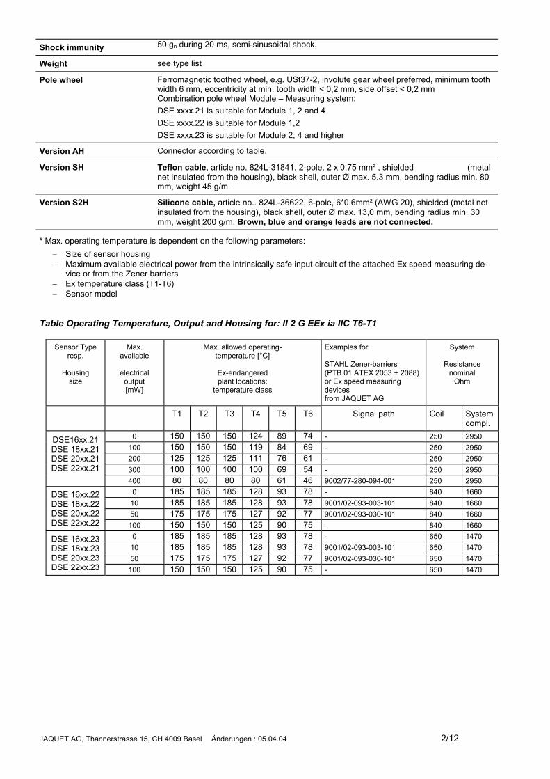
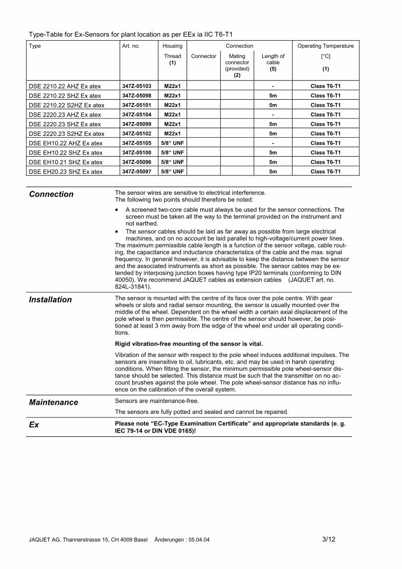
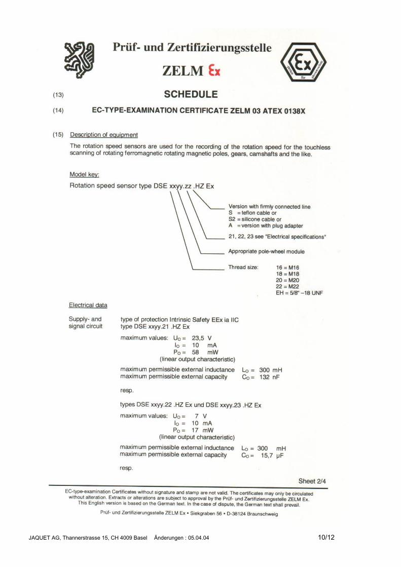
Technical DataSignal output * Using the sensor together with a toothed wheel having involute gear form will generate a
sinusoidal signal. Analysing the frequency will determine the speed. The signal amplitudeis proportional to the rate of change of flux generated by the pole wheel. It principally de-pends on the following parameters:� Linear velocity at the circumference of the toothed wheel� Module of the toothed wheel� Air gap between toothed wheel and sensor’s front surface� Load impedance applied to the sensorImages 1, 2, and 3 show the maximum Peak-Peak voltage, which can be achieved with thedifferent sensor models. Please note that the min/max signal amplitudes should be dimen-sioned in such a way as to be compatible with the instrumentation ( trigger level and maxI/P voltage ). A trigger level of 50mVrms is used as standard with Jaquet tachometers.The minimum measurable speed is then derived from the frequency which generates aminimum amplitude of 50mVrms.Note: For use in Ex zones the lower air gap limits shown in table 1 must not be re-duced.
Frequency range 0,05 Hz...20 kHz
Noise immunity According to 89/336/EG / EN 50081-2 / EN 50082-2
Insulation Housing, cable shield and coils galvanically isolated (500 V/50 Hz/ 1 min)
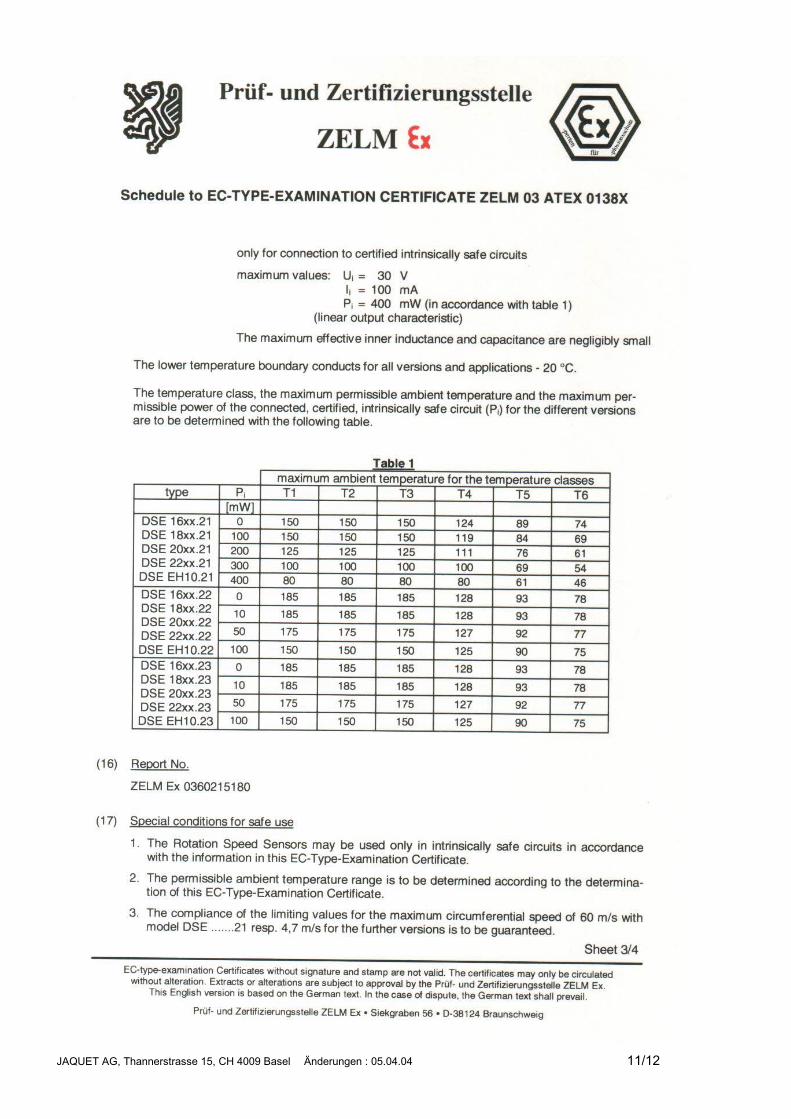
Operating temperature * See tables on page 2. Please note “EC-Type Examination Certificate”.
Housing * Stainless machining steel X12CrNiS188, material no. 1.4305, front side hermeticallysealed. Electronic components potted in chemical and age proof synthetic resin.Dimensions according to drawing and table. Maximum allowed fixing torque:
35 Nm for M16x1 and 5/8“-18 UNF 50 Nm for M18x1 75 Nm for M22x1
Protection class IP68 (head), IP67 (cable entrance), IP 54 (connector – where used)
Vibration immunity 5 gn in the range of 5...2000 Hz.
JAQUET AG, Thannerstrasse 15, CH 4009 Basel Änderungen : 05.04.04 2/12
Shock immunity 50 gn during 20 ms, semi-sinusoidal shock.
Weight see type list
Pole wheel Ferromagnetic toothed wheel, e.g. USt37-2, involute gear wheel preferred, minimum toothwidth 6 mm, eccentricity at min. tooth width < 0,2 mm, side offset < 0,2 mmCombination pole wheel Module – Measuring system:DSE xxxx.21 is suitable for Module 1, 2 and 4DSE xxxx.22 is suitable for Module 1,2DSE xxxx.23 is suitable for Module 2, 4 and higher
Version AH Connector according to table.
Version SH Teflon cable, article no. 824L-31841, 2-pole, 2 x 0,75 mm² , shielded (metalnet insulated from the housing), black shell, outer Ø max. 5.3 mm, bending radius min. 80mm, weight 45 g/m.
Version S2H Silicone cable, article no.. 824L-36622, 6-pole, 6*0.6mm² (AWG 20), shielded (metal netinsulated from the housing), black shell, outer Ø max. 13,0 mm, bending radius min. 30mm, weight 200 g/m. Brown, blue and orange leads are not connected.
* Max. operating temperature is dependent on the following parameters:� Size of sensor housing� Maximum available electrical power from the intrinsically safe input circuit of the attached Ex speed measuring de-
vice or from the Zener barriers� Ex temperature class (T1-T6)� Sensor model
Table Operating Temperature, Output and Housing for: II 2 G EEx ia IIC T6-T1
Sensor Typeresp.
Housingsize
Max.available
electricaloutput[mW]
Max. allowed operating-temperature [°C]
Ex-endangeredplant locations:
temperature class
Examples for
STAHL Zener-barriers(PTB 01 ATEX 2053 + 2088)or Ex speed measuringdevicesfrom JAQUET AG
System
Resistancenominal
Ohm
T1 T2 T3 T4 T5 T6 Signal path Coil Systemcompl.
0 150 150 150 124 89 74 - 250 2950100 150 150 150 119 84 69 - 250 2950200 125 125 125 111 76 61 - 250 2950300 100 100 100 100 69 54 - 250 2950
DSE16xx.21DSE 18xx.21DSE 20xx.21DSE 22xx.21
400 80 80 80 80 61 46 9002/77-280-094-001 250 29500 185 185 185 128 93 78 - 840 1660
10 185 185 185 128 93 78 9001/02-093-003-101 840 166050 175 175 175 127 92 77 9001/02-093-030-101 840 1660
DSE 16xx.22DSE 18xx.22DSE 20xx.22DSE 22xx.22 100 150 150 150 125 90 75 - 840 1660
0 185 185 185 128 93 78 - 650 147010 185 185 185 128 93 78 9001/02-093-003-101 650 147050 175 175 175 127 92 77 9001/02-093-030-101 650 1470
DSE 16xx.23DSE 18xx.23DSE 20xx.23DSE 22xx.23 100 150 150 150 125 90 75 - 650 1470
JAQUET AG, Thannerstrasse 15, CH 4009 Basel Änderungen : 05.04.04 3/12
Type-Table for Ex-Sensors for plant location as per EEx ia IIC T6-T1Type Art. no. Housing Connection Operating Temperature
Thread(1)
Connector Matingconnector(provided)
(2)
Length ofcable
(5)
[°C]
(1)
DSE 2210.22 AHZ Ex atex 347Z-05103 M22x1 - Class T6-T1
DSE 2210.22 SHZ Ex atex 347Z-05098 M22x1 5m Class T6-T1
DSE 2210.22 S2HZ Ex atex 347Z-05101 M22x1 5m Class T6-T1
DSE 2220.23 AHZ Ex atex 347Z-05104 M22x1 - Class T6-T1
DSE 2220.23 SHZ Ex atex 347Z-05099 M22x1 5m Class T6-T1
DSE 2220.23 S2HZ Ex atex 347Z-05102 M22x1 5m Class T6-T1
DSE EH10.22 AHZ Ex atex 347Z-05105 5/8“ UNF - Class T6-T1
DSE EH10.22 SHZ Ex atex 347Z-05100 5/8“ UNF 5m Class T6-T1
DSE EH10.21 SHZ Ex atex 347Z-05096 5/8“ UNF 5m Class T6-T1
DSE EH20.23 SHZ Ex atex 347Z-05097 5/8“ UNF 5m Class T6-T1
Connection The sensor wires are sensitive to electrical interference.The following two points should therefore be noted:� A screened two-core cable must always be used for the sensor connections. The
screen must be taken all the way to the terminal provided on the instrument andnot earthed.
� The sensor cables should be laid as far away as possible from large electricalmachines, and on no account be laid parallel to high-voltage/current power lines.
The maximum permissible cable length is a function of the sensor voltage, cable rout-ing, the capacitance and inductance characteristics of the cable and the max. signalfrequency. In general however, it is advisable to keep the distance between the sensorand the associated instruments as short as possible. The sensor cables may be ex-tended by interposing junction boxes having type IP20 terminals (conforming to DIN40050). We recommend JAQUET cables as extension cables (JAQUET art. no.824L-31841).
Installation The sensor is mounted with the centre of its face over the pole centre. With gearwheels or slots and radial sensor mounting, the sensor is usually mounted over themiddle of the wheel. Dependent on the wheel width a certain axial displacement of thepole wheel is then permissible. The centre of the sensor should however, be posi-tioned at least 3 mm away from the edge of the wheel end under all operating condi-tions.
Rigid vibration-free mounting of the sensor is vital.
Vibration of the sensor with respect to the pole wheel induces additional impulses. Thesensors are insensitive to oil, lubricants, etc. and may be used in harsh operatingconditions. When fitting the sensor, the minimum permissible pole wheel-sensor dis-tance should be selected. This distance must be such that the transmitter on no ac-count brushes against the pole wheel. The pole wheel-sensor distance has no influ-ence on the calibration of the overall system.
Maintenance Sensors are maintenance-free.
The sensors are fully potted and sealed and cannot be repaired.
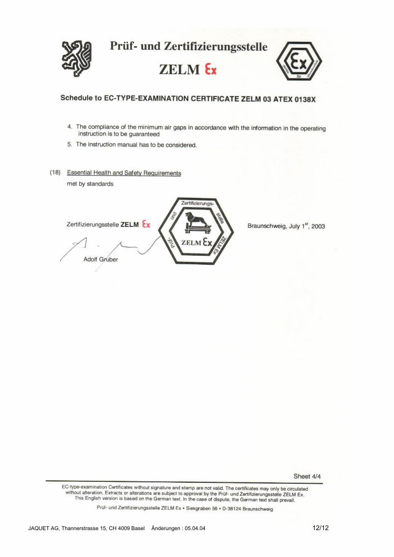
Ex Please note “EC-Type Examination Certificate” and appropriate standards (e. g.IEC 79-14 or DIN VDE 0165)!
JAQUET AG, Thannerstrasse 15, CH 4009 Basel Änderungen : 05.04.04 4/12
Image 1 :
Image 2 :
Image 3 :
Messystem DSE ____.21
-10,00
0,00
10,00
20,00
30,00
40,00
50,00
0 1 2 3 4 5 6
Luftspalt (mm)
Upp
M = 1 (60 m/s)
M = 2 (60 m/s)
M = 4 (60 m/s)
2 * U0
Messystem DSE ____.22
-2,00
0,00
2,00
4,00
6,00
8,00
10,00
12,00
14,00
16,00
0 1 2 3 4 5 6
Luftspalt (mm)
Upp
M = 1 (4,7 m/s)
M = 2 (4,7 m/s)
2*U0
Messystem DSE ____.23
-2,00
0,00
2,00
4,00
6,00
8,00
10,00
12,00
14,00
16,00
0 1 2 3 4 5 6
Luftspalt (mm)
Upp
M = 1 (4,7 m/s)
M = 2 (4,7 m/s)
M = 4 (4,7 m/s)
2*U0
JAQUET AG, Thannerstrasse 15, CH 4009 Basel Änderungen : 05.04.04 5/12
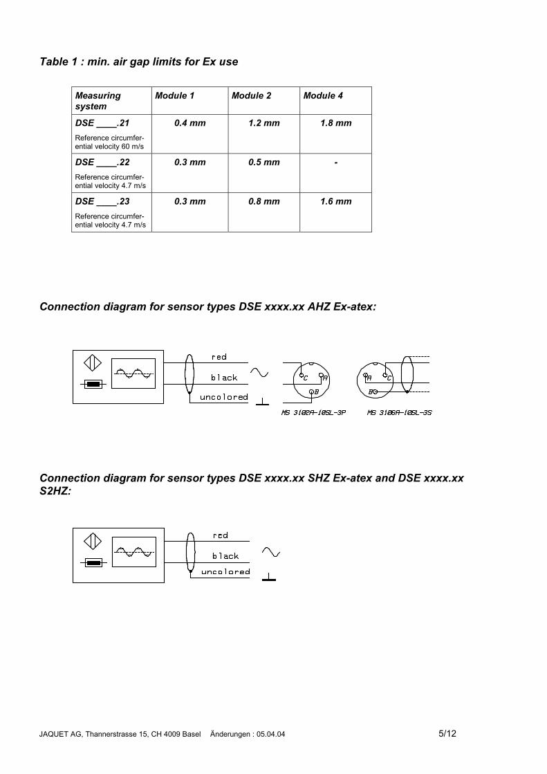
Table 1 : min. air gap limits for Ex use
Measuringsystem
Module 1 Module 2 Module 4
DSE ____.21Reference circumfer-ential velocity 60 m/s
0.4 mm 1.2 mm 1.8 mm
DSE ____.22Reference circumfer-ential velocity 4.7 m/s
0.3 mm 0.5 mm -
DSE ____.23Reference circumfer-ential velocity 4.7 m/s
0.3 mm 0.8 mm 1.6 mm
Connection diagram for sensor types DSE xxxx.xx AHZ Ex-atex:
Connection diagram for sensor types DSE xxxx.xx SHZ Ex-atex and DSE xxxx.xxS2HZ:
JAQUET AG, Thannerstrasse 15, CH 4009 Basel Änderungen : 05.04.04 6/12
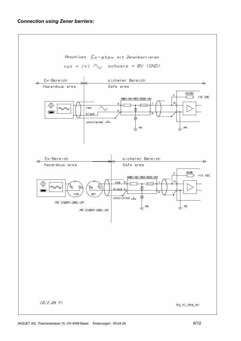
Connection using Zener barriers:
JAQUET AG, Thannerstrasse 15, CH 4009 Basel Änderungen : 05.04.04 7/12
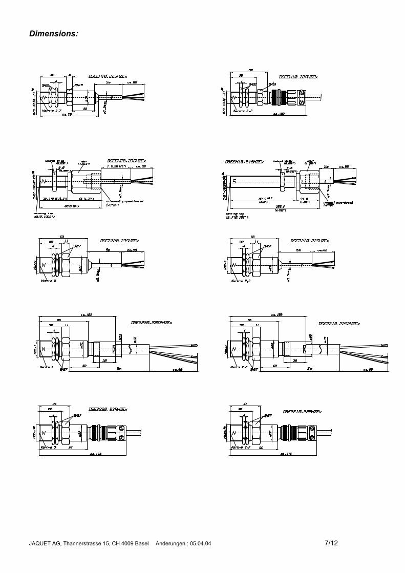
Dimensions:
JAQUET AG, Thannerstrasse 15, CH 4009 Basel Änderungen : 05.04.04 8/12
JAQUET AG, Thannerstrasse 15, CH 4009 Basel Änderungen : 05.04.04 9/12
JAQUET AG, Thannerstrasse 15, CH 4009 Basel Änderungen : 05.04.04 10/12
JAQUET AG, Thannerstrasse 15, CH 4009 Basel Änderungen : 05.04.04 11/12
JAQUET AG, Thannerstrasse 15, CH 4009 Basel Änderungen : 05.04.04 12/12
JAQUET AG, Thannerstrasse 15, CH 4009 Basel Änderungen : 01.09.03 1/10
Ferrostat Speed SensorSeries DSFExplosion Proof Versions EEx
DSF ..10.** .HVEx
ATEXOperating Instructions374E-64368Valid from lot nr. 0103
GeneralFunction The DSF series Ferrostat speed sensors are suitable for use with a pole wheel to gener-
ate speed proportional frequency signals. They exhibit dynamic behaviour, whereby pulsegeneration down to 0.05 Hz is guaranteed. The sensing element is a magnetically biasedHall device, followed by an amplifier having a trigger characteristic and short circuit proofoutput stage.
Use in potentially explosiveenvironment EEx
For operation in hazardous areas the restrictions given in the EC Type ExaminationCertificate must be adhered to.
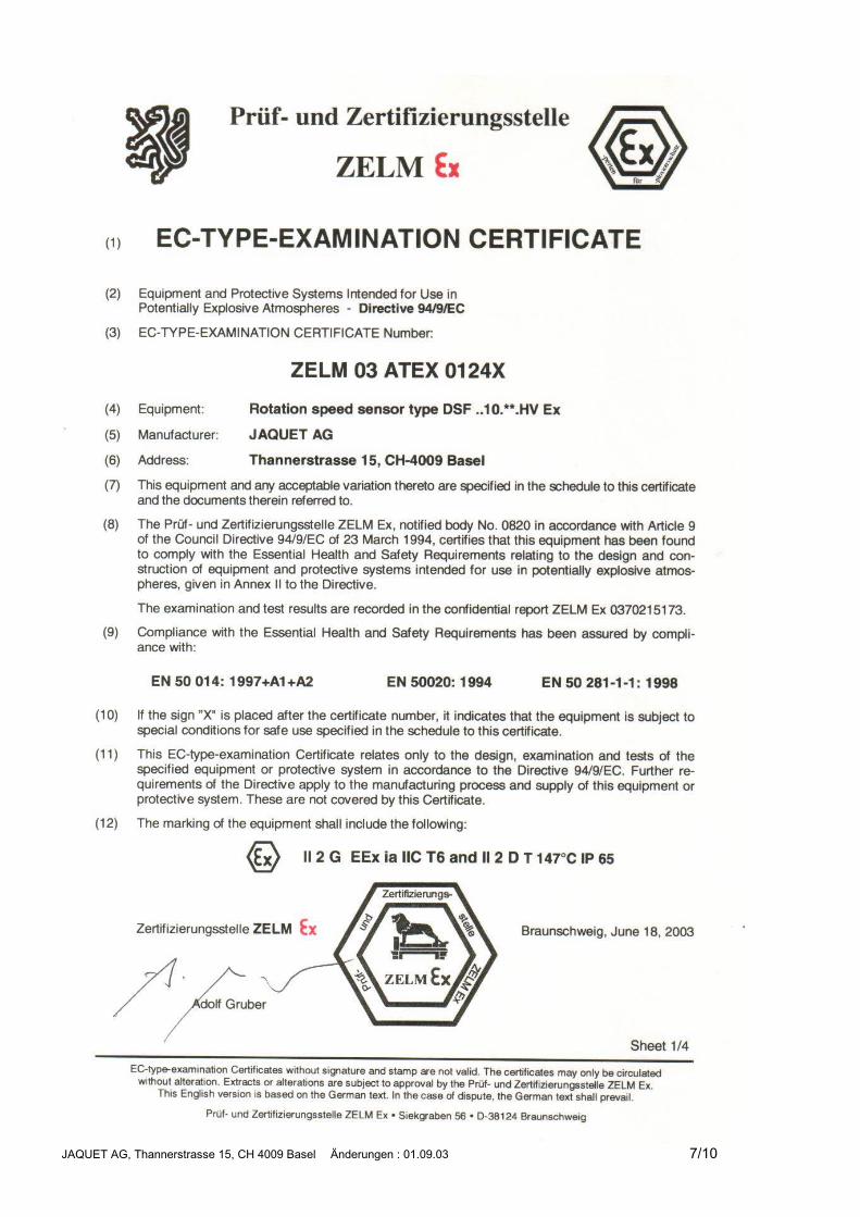
DSF xx10.00 xHV Ex series sensors are certified intrinsically safe II 2 G EEx ia IIC T6-T1 for use in flammable gas atmospheres, and as II 2 D T147°C IP65 for use in flammabledust atmospheres. EC Type Examination Certificate no. ZELM 03 ATEX 0124X.
A copy of the EC Type Examination Certificate forms a constituent part of these operatinginstructions.
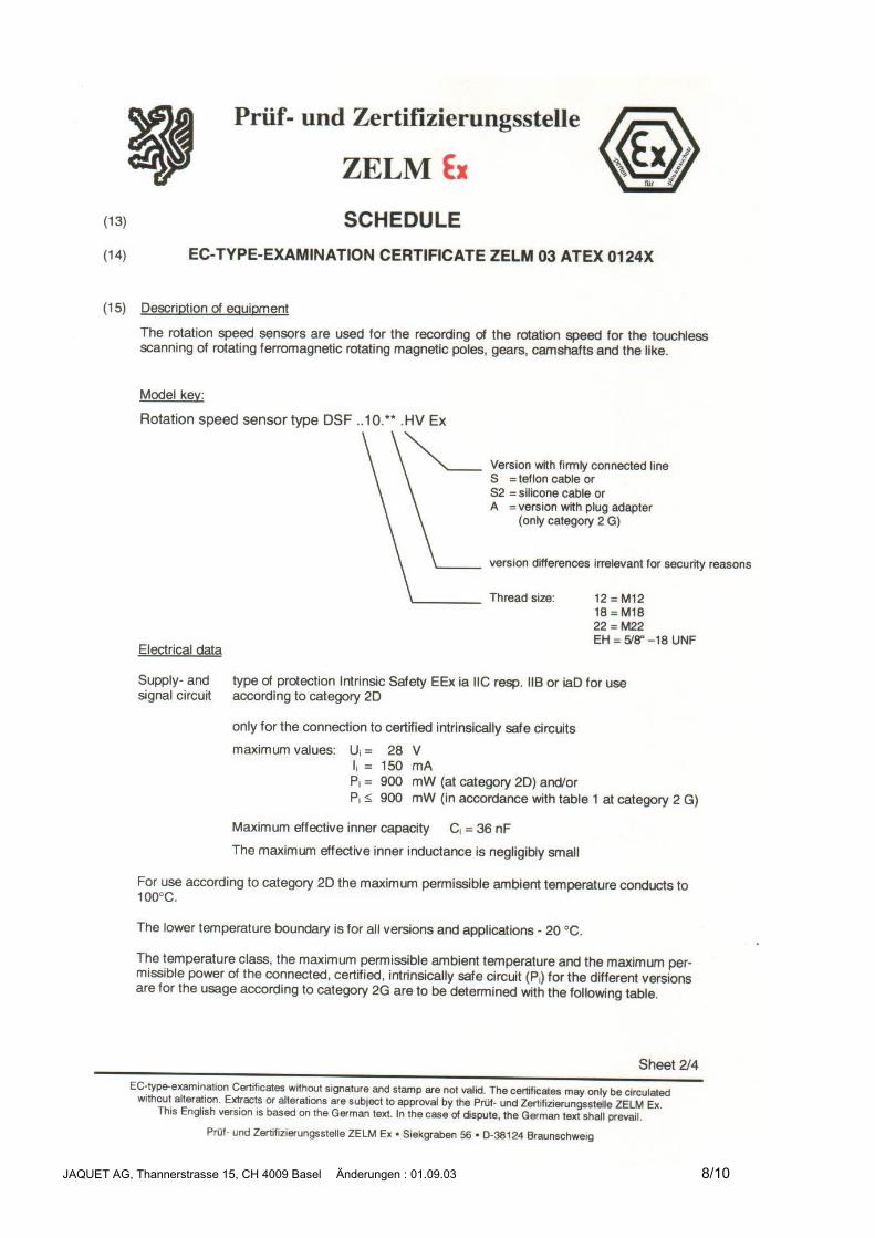
Technical DataSupply voltage * 8 ... 28 VDC, max. superimposed AC ripple of 25mVpp.
The voltage drop as a result of the cable impedance and Zener barrier series resistancemust be allowed for!Protected against reverse polarity.
Current consumption max. 15mA (without load)
Signal output * Square wave from push-pull output stage, DC coupled to the supply (0V = reference volt-age ), Load current max. 25mA,Output voltage HI: > Supply voltage - 4 Volt at Isource = 25mAOutput voltage LO: < 2 Volt at Isink = 25mAThe voltage drop as a result of the cable impedance and Zener barrier series resistancemust be allowed for!Short circuit proof and protected against reverse polarity.
Frequency range 0,05Hz...20 kHz
Noise immunity In accordance with 89/336/EG / EN 50081-2 / EN 50082-2
Isolation Housing, cable screen and electronics galvanically separated (500 V/50 Hz/ 1 Min.)
Operating temperature * See tables on following pages. The restrictions given in the EC Type Examination Cer-tificate must be adhered to.
Housing * Stainless steel X12CrNiS188, material number 1.4305, front side hermetically sealed,electronic components potted in a chemical and age proof ceramic.Dimensions according to table and drawings. Maximum permissible tightening torque:12 Nm for M12x1 25 Nm for M14x1 35 Nm for M16x150 Nm for M18x1 75 Nm for M22x1
Protection class IP68 (Head), IP67 (cable connection), IP 54 (where connector used)
Ex protection * II 2 G EEx ia IIC T6-T1 (explosive gas)II 2 D 147°C IP 65 (explosive dust)The restrictions given in the EC Type Examination Certificate must be adhered to.
Vibration immunity 5 gn in the range 5...2000Hz.
JAQUET AG, Thannerstrasse 15, CH 4009 Basel Änderungen : 01.09.03 2/10
Shock immunity 50 gn during 20 ms, half sine wave impact.
Weight According to table
Pole wheel Ferromagnetic toothed wheel, material e.g.. USt37-2, involute gear wheels preferred, Mod-ule �1, tooth width min. 6 mm, sidewise movement at min. tooth width< 0,2 mm, eccentricity < 0,2 mm.� Pole wheel – sensor gap with Module 1: 0,2...1,0 mm Module 2: 0,2...2,5 mm
�Module 4: 0,2...4,5 mm
Version AH Connector per table.
Version SH Teflon cable, Art.-Nr. 824L-35053, 4-pole, 4 x 0,24 mm² (AWG 24), screened wires (meshscreen, isolated from housing), white outer shell Ø max. 4,0 mm, bending radius min. 60mm, weight 32 g/m. The brown wire is not used.
Version S2H Silicone cable, Art-Nr. 824L-36622, 6-pole, 6*0.6mm² (AWG 20), screened wires (meshscreen, isolated from housing), black outer shell Ø max. 13,0 mm, bending radius min. 30mm, weight 200 g/m. The brown, blue and orange wires are not used.
* The maximum permissible operating temperature depends upon the following parameters, as shown in the table below:� Sensor housing size� Maximum available electrical power from the intrinsically safe sensor power supply and from the intrinsically safe input circuit of
the attached instrumentation and any Zener barriers.� Ex Temperature class (T1-T6)
Operating temperature for II 2 D T 147°C IP65 : -20 / + 100°CWhere dust clouds are present, the surface temperature of the sensor must not exceed 2/3 of the ignition temperature ofthe corresponding dust / air mixture.In the event of dust coatings being present, the surface temperature of the sensor must not exceed the limits defined inEN 50281-1-2.
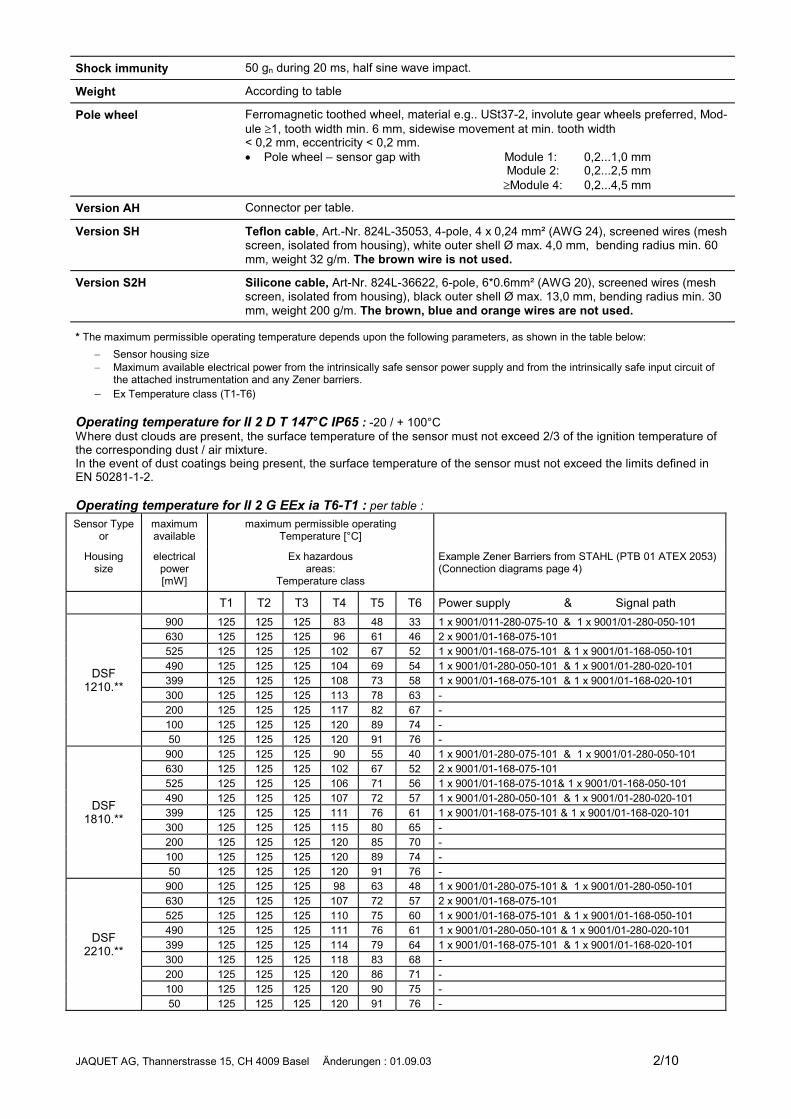
Operating temperature for II 2 G EEx ia T6-T1 : per table :Sensor Type
ormaximumavailable
maximum permissible operatingTemperature [°C]
Housingsize
electricalpower[mW]
Ex hazardousareas:
Temperature class
Example Zener Barriers from STAHL (PTB 01 ATEX 2053)(Connection diagrams page 4)
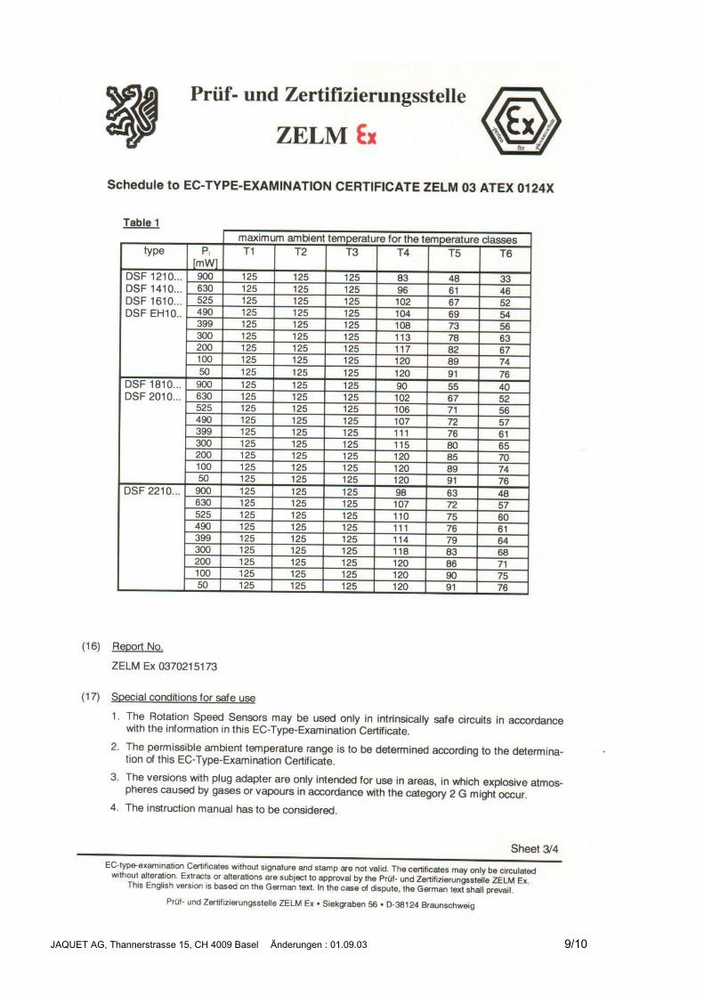
T1 T2 T3 T4 T5 T6 Power supply & Signal path900 125 125 125 83 48 33 1 x 9001/011-280-075-10 & 1 x 9001/01-280-050-101630 125 125 125 96 61 46 2 x 9001/01-168-075-101525 125 125 125 102 67 52 1 x 9001/01-168-075-101 & 1 x 9001/01-168-050-101490 125 125 125 104 69 54 1 x 9001/01-280-050-101 & 1 x 9001/01-280-020-101399 125 125 125 108 73 58 1 x 9001/01-168-075-101 & 1 x 9001/01-168-020-101300 125 125 125 113 78 63 -200 125 125 125 117 82 67 -100 125 125 125 120 89 74 -
DSF1210.**
50 125 125 125 120 91 76 -900 125 125 125 90 55 40 1 x 9001/01-280-075-101 & 1 x 9001/01-280-050-101630 125 125 125 102 67 52 2 x 9001/01-168-075-101525 125 125 125 106 71 56 1 x 9001/01-168-075-101& 1 x 9001/01-168-050-101490 125 125 125 107 72 57 1 x 9001/01-280-050-101 & 1 x 9001/01-280-020-101399 125 125 125 111 76 61 1 x 9001/01-168-075-101 & 1 x 9001/01-168-020-101300 125 125 125 115 80 65 -200 125 125 125 120 85 70 -100 125 125 125 120 89 74 -
DSF1810.**
50 125 125 125 120 91 76 -900 125 125 125 98 63 48 1 x 9001/01-280-075-101 & 1 x 9001/01-280-050-101630 125 125 125 107 72 57 2 x 9001/01-168-075-101525 125 125 125 110 75 60 1 x 9001/01-168-075-101 & 1 x 9001/01-168-050-101490 125 125 125 111 76 61 1 x 9001/01-280-050-101 & 1 x 9001/01-280-020-101399 125 125 125 114 79 64 1 x 9001/01-168-075-101 & 1 x 9001/01-168-020-101300 125 125 125 118 83 68 -200 125 125 125 120 86 71 -100 125 125 125 120 90 75 -
DSF2210.**
50 125 125 125 120 91 76 -
JAQUET AG, Thannerstrasse 15, CH 4009 Basel Änderungen : 01.09.03 3/10
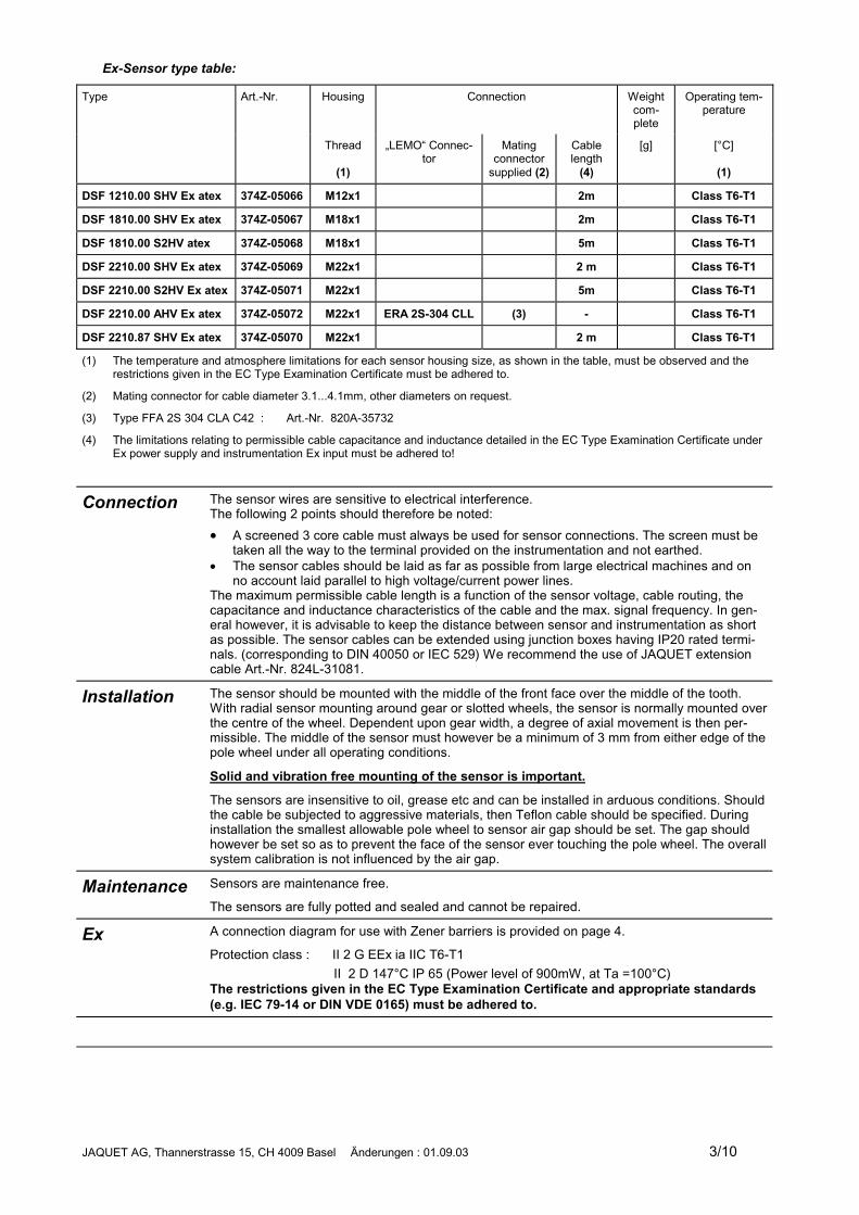
Ex-Sensor type table:
Type Art.-Nr. Housing Connection Weightcom-plete
Operating tem-perature
Thread
(1)
„LEMO“ Connec-tor
Matingconnector
supplied (2)
Cablelength
(4)
[g] [°C]
(1)
DSF 1210.00 SHV Ex atex 374Z-05066 M12x1 2m Class T6-T1
DSF 1810.00 SHV Ex atex 374Z-05067 M18x1 2m Class T6-T1
DSF 1810.00 S2HV atex 374Z-05068 M18x1 5m Class T6-T1
DSF 2210.00 SHV Ex atex 374Z-05069 M22x1 2 m Class T6-T1
DSF 2210.00 S2HV Ex atex 374Z-05071 M22x1 5m Class T6-T1
DSF 2210.00 AHV Ex atex 374Z-05072 M22x1 ERA 2S-304 CLL (3) - Class T6-T1
DSF 2210.87 SHV Ex atex 374Z-05070 M22x1 2 m Class T6-T1
(1) The temperature and atmosphere limitations for each sensor housing size, as shown in the table, must be observed and therestrictions given in the EC Type Examination Certificate must be adhered to.
(2) Mating connector for cable diameter 3.1...4.1mm, other diameters on request.
(3) Type FFA 2S 304 CLA C42 : Art.-Nr. 820A-35732
(4) The limitations relating to permissible cable capacitance and inductance detailed in the EC Type Examination Certificate underEx power supply and instrumentation Ex input must be adhered to!
Connection The sensor wires are sensitive to electrical interference.The following 2 points should therefore be noted:� A screened 3 core cable must always be used for sensor connections. The screen must be
taken all the way to the terminal provided on the instrumentation and not earthed.� The sensor cables should be laid as far as possible from large electrical machines and on
no account laid parallel to high voltage/current power lines.The maximum permissible cable length is a function of the sensor voltage, cable routing, thecapacitance and inductance characteristics of the cable and the max. signal frequency. In gen-eral however, it is advisable to keep the distance between sensor and instrumentation as shortas possible. The sensor cables can be extended using junction boxes having IP20 rated termi-nals. (corresponding to DIN 40050 or IEC 529) We recommend the use of JAQUET extensioncable Art.-Nr. 824L-31081.
Installation The sensor should be mounted with the middle of the front face over the middle of the tooth.With radial sensor mounting around gear or slotted wheels, the sensor is normally mounted overthe centre of the wheel. Dependent upon gear width, a degree of axial movement is then per-missible. The middle of the sensor must however be a minimum of 3 mm from either edge of thepole wheel under all operating conditions.
Solid and vibration free mounting of the sensor is important.
The sensors are insensitive to oil, grease etc and can be installed in arduous conditions. Shouldthe cable be subjected to aggressive materials, then Teflon cable should be specified. Duringinstallation the smallest allowable pole wheel to sensor air gap should be set. The gap shouldhowever be set so as to prevent the face of the sensor ever touching the pole wheel. The overallsystem calibration is not influenced by the air gap.
Maintenance Sensors are maintenance free.
The sensors are fully potted and sealed and cannot be repaired.
Ex A connection diagram for use with Zener barriers is provided on page 4.
Protection class : II 2 G EEx ia IIC T6-T1 II 2 D 147°C IP 65 (Power level of 900mW, at Ta =100°C)The restrictions given in the EC Type Examination Certificate and appropriate standards(e.g. IEC 79-14 or DIN VDE 0165) must be adhered to.
JAQUET AG, Thannerstrasse 15, CH 4009 Basel Änderungen : 01.09.03 4/10
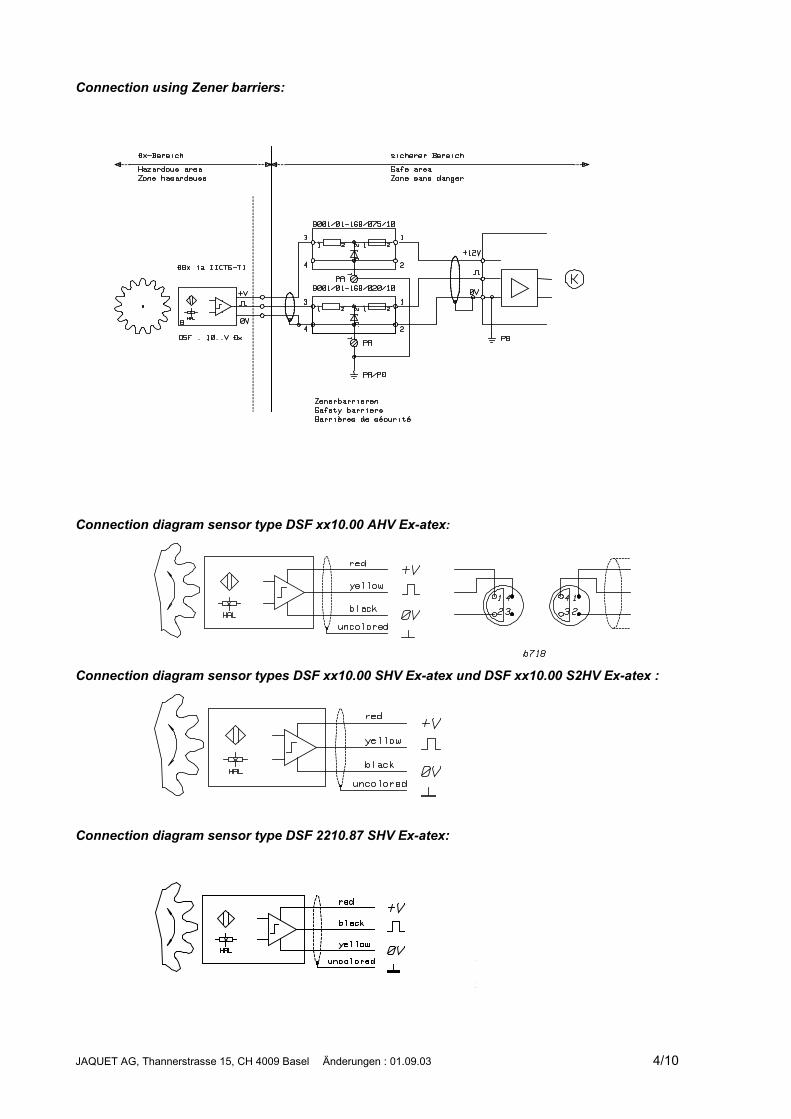
Connection using Zener barriers:
Connection diagram sensor type DSF xx10.00 AHV Ex-atex:
Connection diagram sensor types DSF xx10.00 SHV Ex-atex und DSF xx10.00 S2HV Ex-atex :
Connection diagram sensor type DSF 2210.87 SHV Ex-atex:
JAQUET AG, Thannerstrasse 15, CH 4009 Basel Änderungen : 01.09.03 5/10
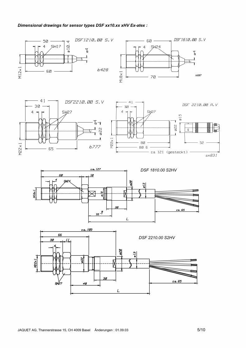
Dimensional drawings for sensor types DSF xx10.xx xHV Ex-atex :
DSF 1810.00 S2HV
DSF 2210.00 S2HV
JAQUET AG, Thannerstrasse 15, CH 4009 Basel Änderungen : 01.09.03 6/10
JAQUET AG, Thannerstrasse 15, CH 4009 Basel Änderungen : 01.09.03 7/10
JAQUET AG, Thannerstrasse 15, CH 4009 Basel Änderungen : 01.09.03 8/10
JAQUET AG, Thannerstrasse 15, CH 4009 Basel Änderungen : 01.09.03 9/10
JAQUET AG, Thannerstrasse 15, CH 4009 Basel Änderungen : 01.09.03 10/10
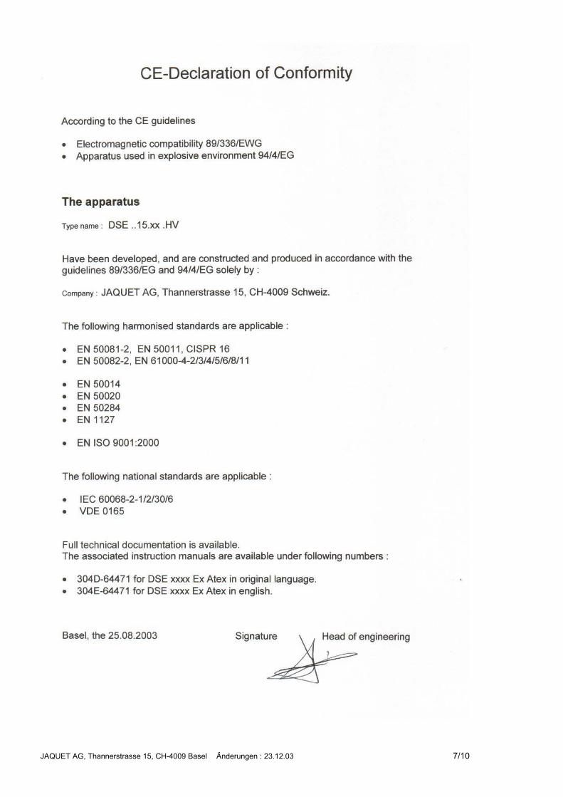
JAQUET AG, Thannerstrasse 15, CH-4009 Basel Änderungen : 23.12.03 1/10
Ferrostat Speed SensorSeries DSF ..15.01Explosion Proof Versions EEx
DSF ..15.01 .HVEx
ATEXOperating Instructions304E-64471valid from lot no. 3003
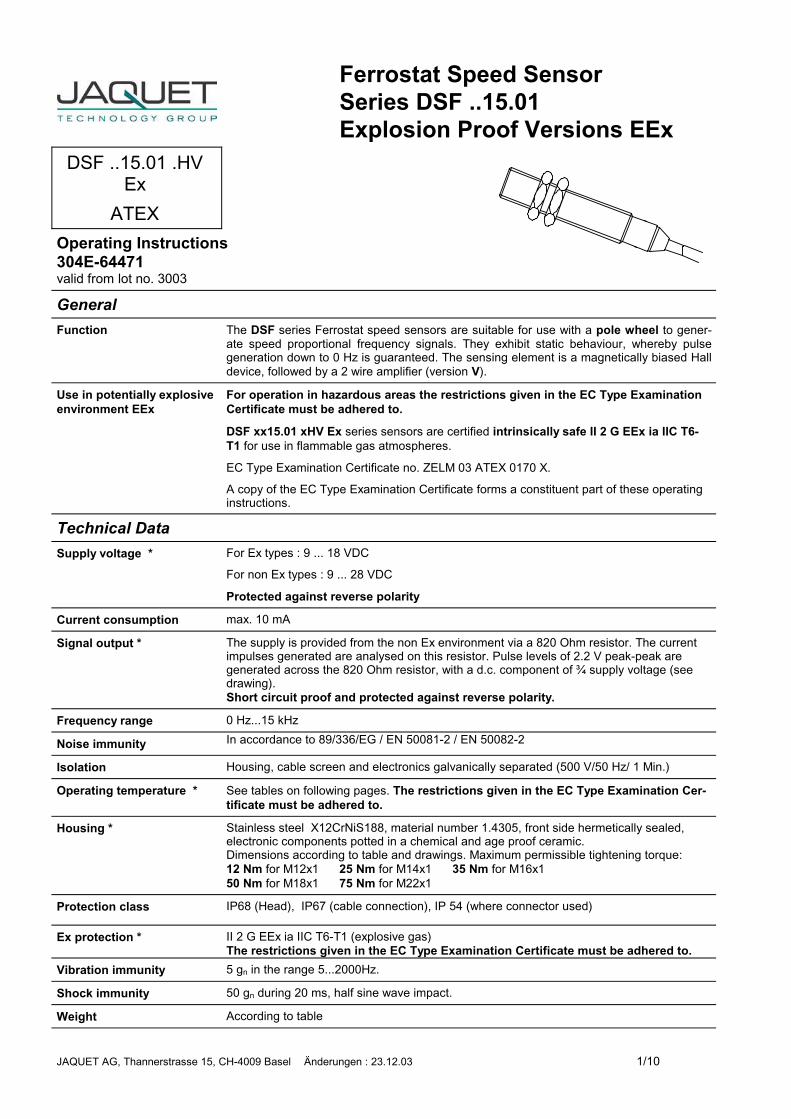
GeneralFunction The DSF series Ferrostat speed sensors are suitable for use with a pole wheel to gener-
ate speed proportional frequency signals. They exhibit static behaviour, whereby pulsegeneration down to 0 Hz is guaranteed. The sensing element is a magnetically biased Halldevice, followed by a 2 wire amplifier (version V).
Use in potentially explosiveenvironment EEx
For operation in hazardous areas the restrictions given in the EC Type ExaminationCertificate must be adhered to.
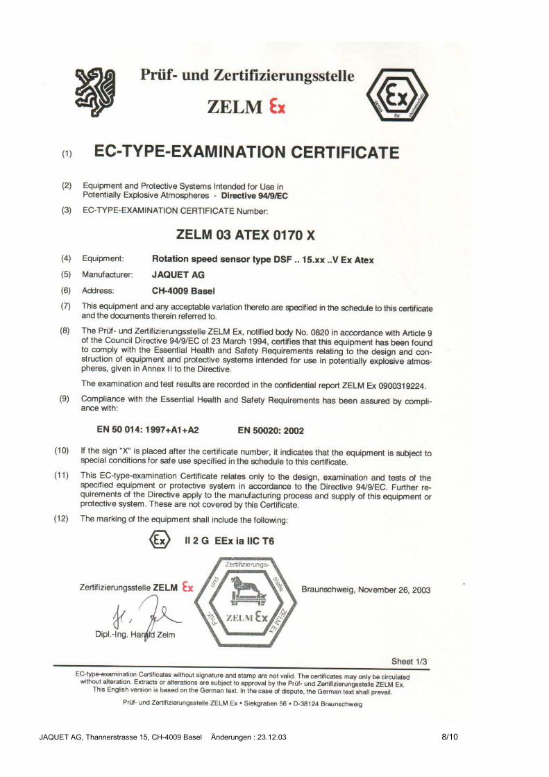
DSF xx15.01 xHV Ex series sensors are certified intrinsically safe II 2 G EEx ia IIC T6-T1 for use in flammable gas atmospheres.
EC Type Examination Certificate no. ZELM 03 ATEX 0170 X.
A copy of the EC Type Examination Certificate forms a constituent part of these operatinginstructions.
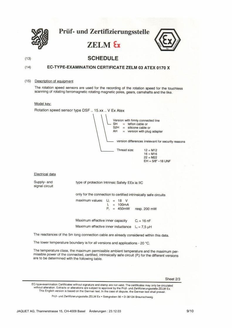
Technical DataSupply voltage * For Ex types : 9 ... 18 VDC
For non Ex types : 9 ... 28 VDC
Protected against reverse polarity
Current consumption max. 10 mA
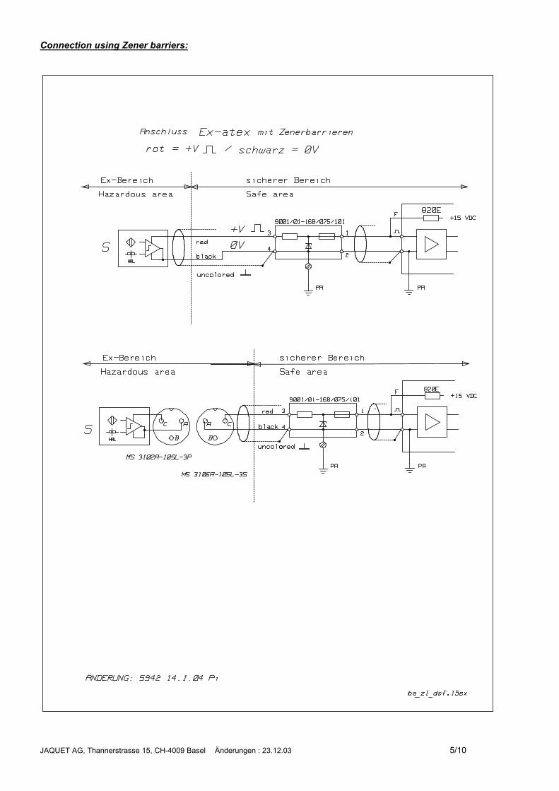
Signal output * The supply is provided from the non Ex environment via a 820 Ohm resistor. The currentimpulses generated are analysed on this resistor. Pulse levels of 2.2 V peak-peak aregenerated across the 820 Ohm resistor, with a d.c. component of ¾ supply voltage (seedrawing).Short circuit proof and protected against reverse polarity.
Frequency range 0 Hz...15 kHz
Noise immunity In accordance to 89/336/EG / EN 50081-2 / EN 50082-2
Isolation Housing, cable screen and electronics galvanically separated (500 V/50 Hz/ 1 Min.)
Operating temperature * See tables on following pages. The restrictions given in the EC Type Examination Cer-tificate must be adhered to.
Housing * Stainless steel X12CrNiS188, material number 1.4305, front side hermetically sealed,electronic components potted in a chemical and age proof ceramic.Dimensions according to table and drawings. Maximum permissible tightening torque:12 Nm for M12x1 25 Nm for M14x1 35 Nm for M16x150 Nm for M18x1 75 Nm for M22x1
Protection class IP68 (Head), IP67 (cable connection), IP 54 (where connector used)
Ex protection * II 2 G EEx ia IIC T6-T1 (explosive gas)The restrictions given in the EC Type Examination Certificate must be adhered to.
Vibration immunity 5 gn in the range 5...2000Hz.
Shock immunity 50 gn during 20 ms, half sine wave impact.
Weight According to table
JAQUET AG, Thannerstrasse 15, CH-4009 Basel Änderungen : 23.12.03 2/10
Pole wheel Ferromagnetic toothed wheel, material e.g. USt37-2, involute gear wheels preferred, Mod-ule �1, tooth width min. 6 mm, sideways movement at min. tooth width< 0,2 mm, eccentricity < 0,2 mm.� Pole wheel – sensor gap with Module 1: 0,2...1,0 mm Module 2: 0,2...2,5 mm
�Module 4: 0,2...4,5 mm
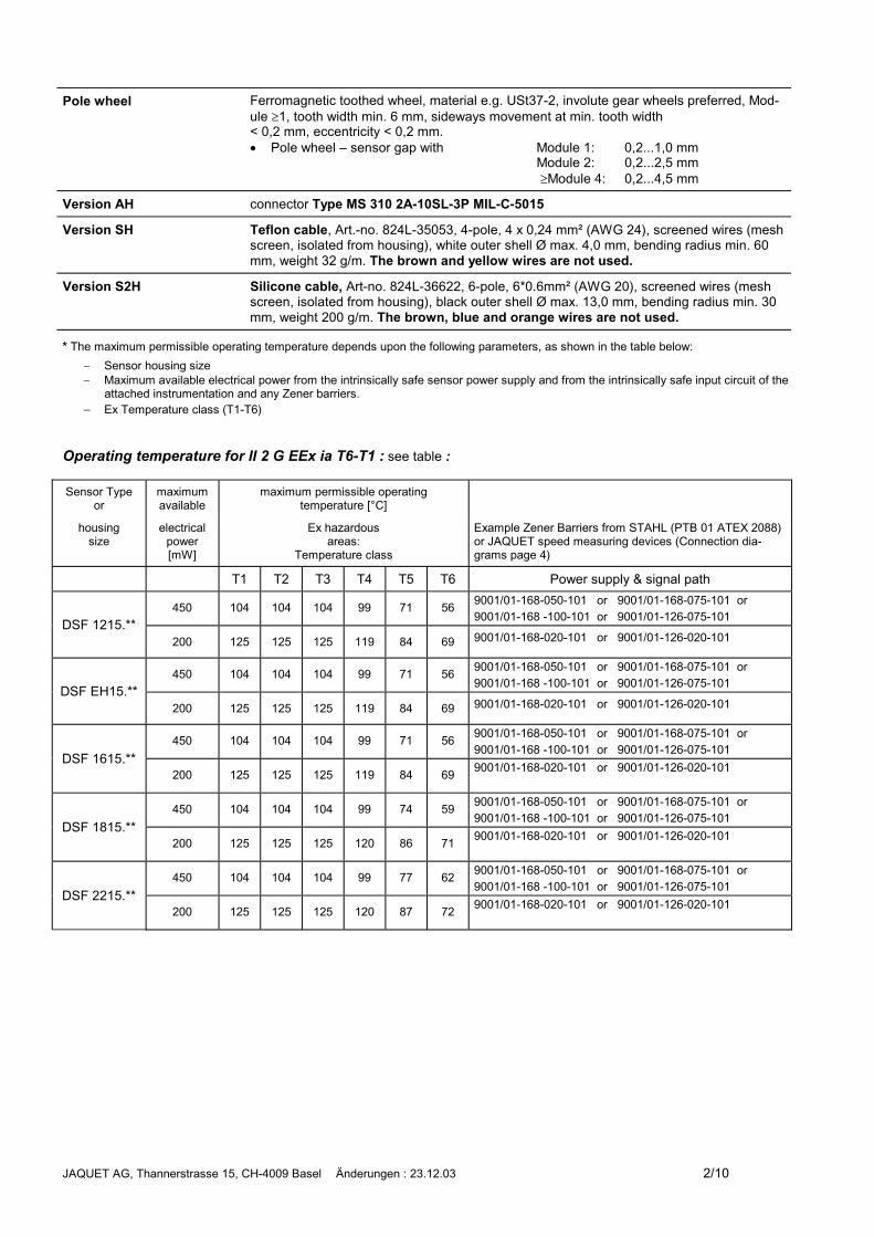
Version AH connector Type MS 310 2A-10SL-3P MIL-C-5015
Version SH Teflon cable, Art.-no. 824L-35053, 4-pole, 4 x 0,24 mm² (AWG 24), screened wires (meshscreen, isolated from housing), white outer shell Ø max. 4,0 mm, bending radius min. 60mm, weight 32 g/m. The brown and yellow wires are not used.
Version S2H Silicone cable, Art-no. 824L-36622, 6-pole, 6*0.6mm² (AWG 20), screened wires (meshscreen, isolated from housing), black outer shell Ø max. 13,0 mm, bending radius min. 30mm, weight 200 g/m. The brown, blue and orange wires are not used.
* The maximum permissible operating temperature depends upon the following parameters, as shown in the table below:� Sensor housing size� Maximum available electrical power from the intrinsically safe sensor power supply and from the intrinsically safe input circuit of the
attached instrumentation and any Zener barriers.� Ex Temperature class (T1-T6)
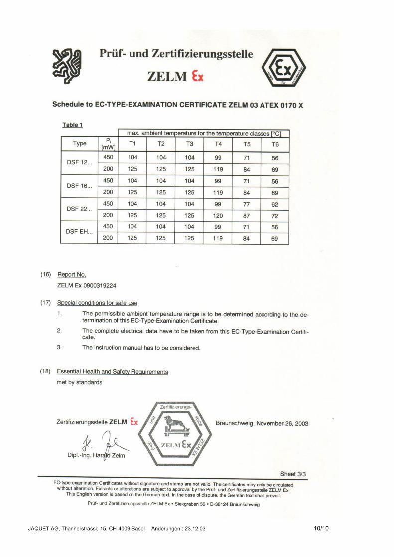
Operating temperature for II 2 G EEx ia T6-T1 : see table :
Sensor Typeor
maximumavailable
maximum permissible operatingtemperature [°C]
housingsize
electricalpower[mW]
Ex hazardousareas:
Temperature class
Example Zener Barriers from STAHL (PTB 01 ATEX 2088)or JAQUET speed measuring devices (Connection dia-grams page 4)
T1 T2 T3 T4 T5 T6 Power supply & signal path
450 104 104 104 99 71 56 9001/01-168-050-101 or 9001/01-168-075-101 or9001/01-168 -100-101 or 9001/01-126-075-101DSF 1215.**
200 125 125 125 119 84 69 9001/01-168-020-101 or 9001/01-126-020-101
450 104 104 104 99 71 56 9001/01-168-050-101 or 9001/01-168-075-101 or9001/01-168 -100-101 or 9001/01-126-075-101DSF EH15.**
200 125 125 125 119 84 69 9001/01-168-020-101 or 9001/01-126-020-101
450 104 104 104 99 71 56 9001/01-168-050-101 or 9001/01-168-075-101 or9001/01-168 -100-101 or 9001/01-126-075-101
DSF 1615.**200 125 125 125 119 84 69 9001/01-168-020-101 or 9001/01-126-020-101
450 104 104 104 99 74 59 9001/01-168-050-101 or 9001/01-168-075-101 or9001/01-168 -100-101 or 9001/01-126-075-101
DSF 1815.**200 125 125 125 120 86 71 9001/01-168-020-101 or 9001/01-126-020-101
450 104 104 104 99 77 62 9001/01-168-050-101 or 9001/01-168-075-101 or9001/01-168 -100-101 or 9001/01-126-075-101
DSF 2215.**200 125 125 125 120 87 72 9001/01-168-020-101 or 9001/01-126-020-101
JAQUET AG, Thannerstrasse 15, CH-4009 Basel Änderungen : 23.12.03 3/10
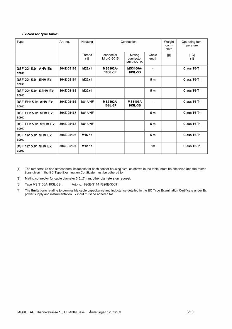
Ex-Sensor type table:
Type Art.-no. Housing Connection Weightcom-plete
Operating tem-perature
Thread(1)
connectorMIL-C-5015
Matingconnector
MIL-C-5015
Cablelength
[g] [°C](1)
DSF 2215.01 AHV Exatex
304Z-05163 M22x1 MS3102A-10SL-3P
MS3106A-10SL-3S
- Class T6-T1
DSF 2215.01 SHV Exatex
304Z-05164 M22x1 5 m Class T6-T1
DSF 2215.01 S2HV Exatex
304Z-05165 M22x1 5 m Class T6-T1
DSF EH15.01 AHV Exatex
304Z-05166 5/8“ UNF MS3102A-10SL-3P
MS3106A10SL-3S
- Class T6-T1
DSF EH15.01 SHV Exatex
304Z-05167 5/8“ UNF 5 m Class T6-T1
DSF EH15.01 S2HV Exatex
304Z-05168 5/8“ UNF 5 m Class T6-T1
DSF 1615.01 SHV Exatex
304Z-05196 M16 * 1 5 m Class T6-T1
DSF 1215.01 SHV Exatex
304Z-05197 M12 * 1 5m Class T6-T1
(1) The temperature and atmosphere limitations for each sensor housing size, as shown in the table, must be observed and the restric-tions given in the EC Type Examination Certificate must be adhered to.
(2) Mating connector for cable diameter 3,5...7 mm, other diameters on request.
(3) Type MS 3106A-10SL-3S : Art.-no. 820E-31141/820E-30691
(4) The limitations relating to permissible cable capacitance and inductance detailed in the EC Type Examination Certificate under Expower supply and instrumentation Ex input must be adhered to!
JAQUET AG, Thannerstrasse 15, CH-4009 Basel Änderungen : 23.12.03 4/10
Connection The sensor wires are sensitive to electrical interference.The following 2 points should therefore be noted:� A screened 2 core cable must always be used for sensor connections. The screen must be
taken all the way to the terminal provided on the instrumentation and not earthed.� The sensor cables should be laid as far as possible from large electrical machines and on
no account laid parallel to high voltage/current power lines.The maximum permissible cable length is a function of the sensor voltage, cable routing, thecapacitance and inductance characteristics of the cable and the max. signal frequency. In gen-eral however, it is advisable to keep the distance between sensor and instrumentation as shortas possible. The sensor cables can be extended using junction boxes having IP20 rated termi-nals. (corresponding to DIN 40050 or IEC 529) We recommend the use of JAQUET extensioncable art. no. 824L-31081.
The screen must be connected to 0 Volts at the analysing device.
Installation The sensor should be mounted with the middle of the front face over the middle of the tooth.With radial sensor mounting around gear or slotted wheels, the sensor is normally mounted overthe centre of the wheel. Dependent upon gear width, a degree of axial movement is then per-missible. The middle of the sensor must however be a minimum of 3 mm from either edge of thepole wheel under all operating conditions.
Solid and vibration free mounting of the sensor is important.
The sensors are insensitive to oil, grease etc and can be installed in arduous conditions. Shouldthe cable be subjected to aggressive materials, then Teflon cable should be specified. Duringinstallation the smallest allowable pole wheel to sensor air gap should be set. The gap shouldhowever be set so as to prevent the face of the sensor ever touching the pole wheel. The overallsystem calibration is not influenced by the air gap.
Maintenance Sensors are maintenance free.
The sensors are fully potted and sealed and cannot be repaired.
Ex A connection diagram for use with Zener barriers is provided on page 5.
Protection class : II 2 G EEx ia IIC T6-T1The restrictions given in the EC Type Examination Certificate and appropriate standards(e.g. IEC 79-14 or DIN VDE 0165) must be adhered to.
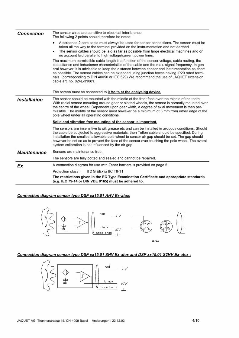
Connection diagram sensor type DSF xx15.01 AHV Ex-atex:
Connection diagram sensor type DSF xx15.01 SHV Ex-atex and DSF xx15.01 S2HV Ex-atex :
JAQUET AG, Thannerstrasse 15, CH-4009 Basel Änderungen : 23.12.03 5/10
Connection using Zener barriers:
JAQUET AG, Thannerstrasse 15, CH-4009 Basel Änderungen : 23.12.03 6/10
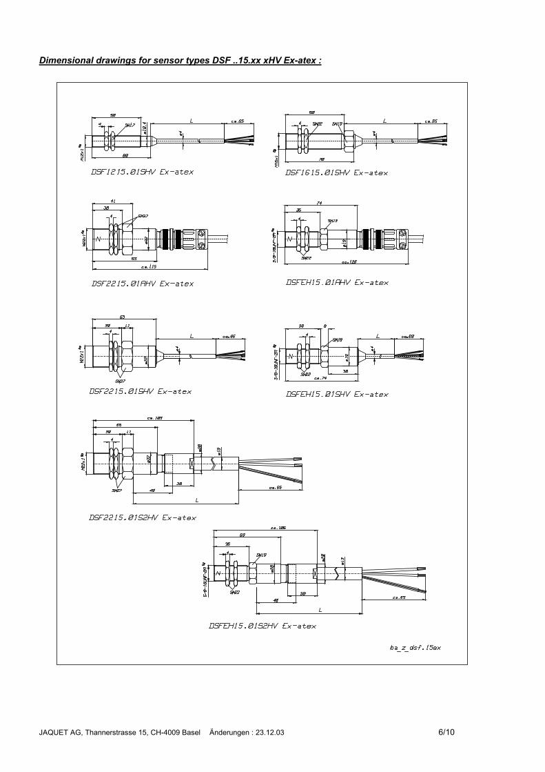
Dimensional drawings for sensor types DSF ..15.xx xHV Ex-atex :
JAQUET AG, Thannerstrasse 15, CH-4009 Basel Änderungen : 23.12.03 7/10
JAQUET AG, Thannerstrasse 15, CH-4009 Basel Änderungen : 23.12.03 8/10
JAQUET AG, Thannerstrasse 15, CH-4009 Basel Änderungen : 23.12.03 9/10
JAQUET AG, Thannerstrasse 15, CH-4009 Basel Änderungen : 23.12.03 10/10
JAQUET AG, Thannerstrasse 15, CH 4009 Basel Änderungen: 01.09.03 1/6
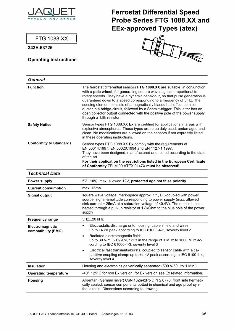
Ferrostat Differential SpeedProbe Series FTG 1088.XX andEEx-approved Types (atex)
FTG 1088.XX343E-63725
Operating instructions
GeneralFunction
Safety Notice
Conformity to Standards
The ferrostat differential sensors FTG 1088.XX are suitable, in conjunctionwith a pole wheel, for generating square wave signals proportional torotary speeds. They have a dynamic behaviour, so that pulse generation isguaranteed down to a speed corresponding to a frequency of 5 Hz. Thesensing element consists of a magnetically biased hall effect semicon-ductor in a bridge-circuit, followed by a Schmitt-trigger. This latter has anopen collector output connected with the positive pole of the power supplythrough a 1.8k resistor.
Sensor types FTG 1088.XX Ex are certified for applications in areas withexplosive atmospheres. These types are to be duly used, undamaged andclean. No modifications are allowed on the sensors if not expressly listedin these operating instructions.
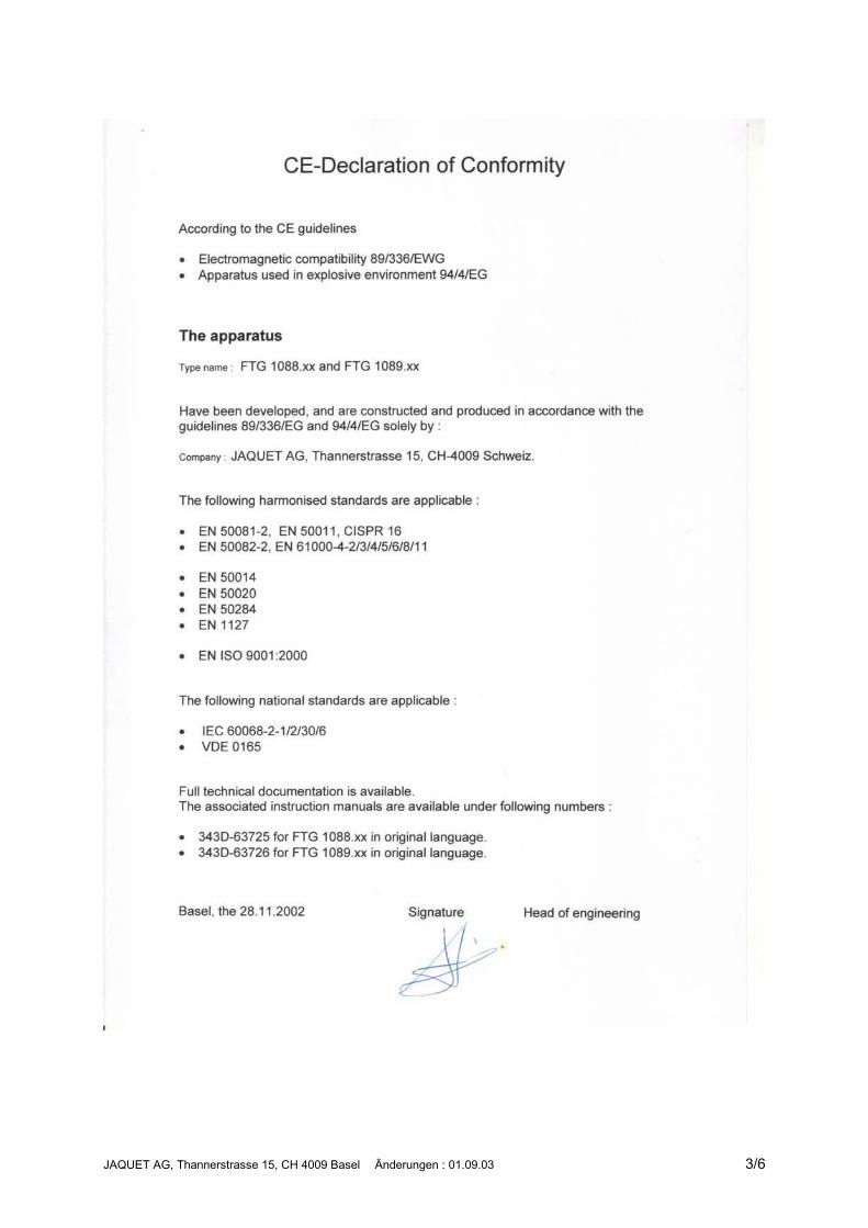
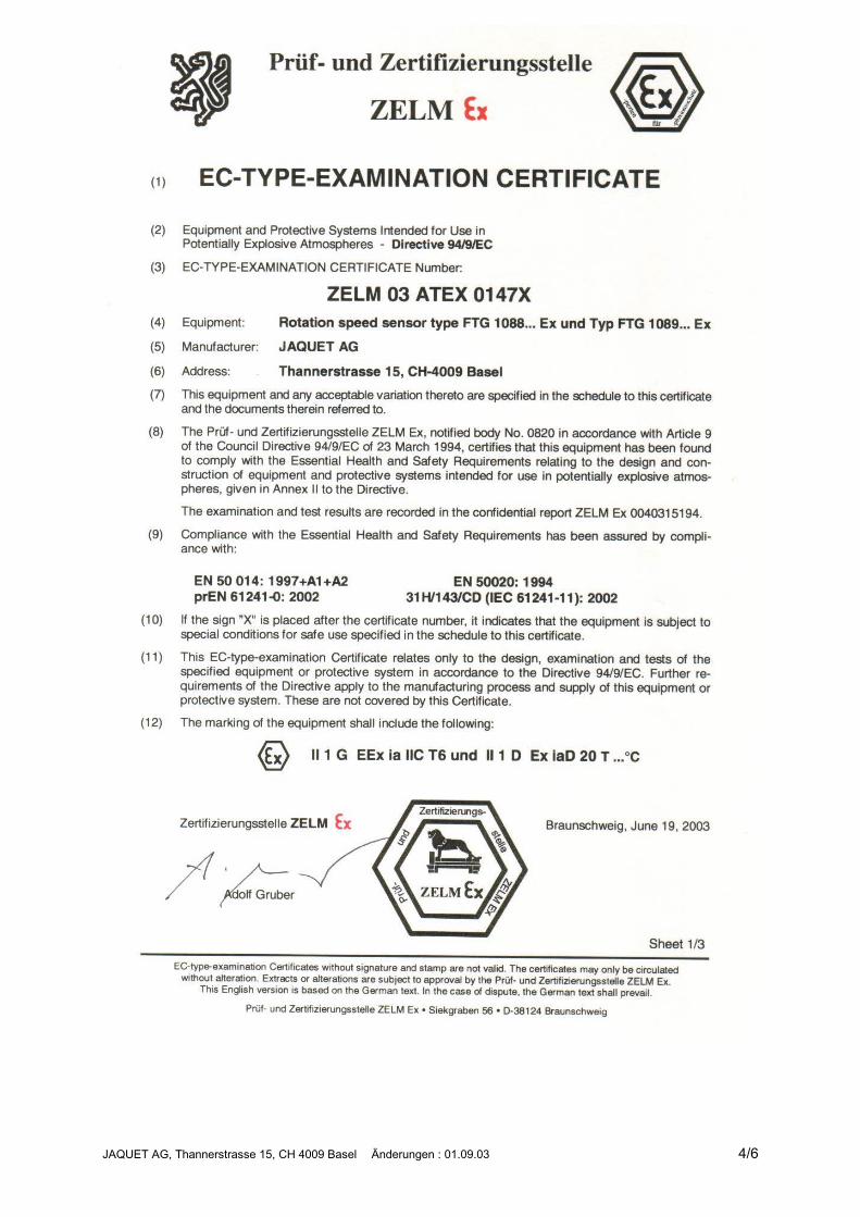
Sensor types FTG 1088.XX Ex comply with the requirements ofEN 50014:1997, EN 50020:1994 and EN 1127-1:1997.They have been designed, manufactured and tested according to the stateof the art.For their application the restrictions listed in the European Certificateof Conformity ZELM 00 ATEX 0147X must be observed!
Technical DataPower supply 5V ±10%, max. allowed 12V, protected against false polarity
Current consumption max. 16mA
Signal output square wave voltage, mark-space approx. 1:1, DC-coupled with powersource, signal-amplitude corresponding to power supply (max. allowedsink current = 25mA at a saturation voltage of <0.4V). The output is con-nected through a pull-up resistor of 1.8kOhm to the plus pole of the powersupply
Frequency range 5Hz...20 kHz
Electromagneticcompatibility (EMC)
� Electrostatic discharge onto housing, cable shield and wires:up to �4 kV peak according to IEC 61000-4-2, severity level 2
� Radiated electromagnetic field:up to 30 V/m, 50% AM, 1kHz in the range of 1 MHz to 1000 MHz ac-cording to IEC 61000-4-3, severity level 3
� Electrical fast transients/bursts, coupled to sensor cable with a ca-pacitive coupling clamp: up to �4 kV peak according to IEC 6100-4-4,severity level 4
Insulation Housing and electronics galvanically separated (500 V/50 Hz/ 1 Min.)
Operating temperature -40/+125°C for non Ex version, for Ex version see Ex related information.
Housing Argentan (German silver) CuNi10Zn42Pb DIN 2.0770, front side hermeti-cally sealed, sensor components potted in chemical and age proof syn-thetic resin. Dimensions according to drawing.
JAQUET AG, Thannerstrasse 15, CH 4009 Basel Änderungen : 01.09.03 2/6
Protection IP68 (head) IP67 (connection)
Vibration immunity 3 g in the range 4...100 Hz
Shock immunity 20 g during 11 ms, half-sine wave
Weight see type list
Pole wheel Ferromagnetic toothed wheel (eg. USt 37-2), involute gear wheel pre-ferred, module �0.5, minimum tooth width 3mm, side offset < 0.2mm, ec-centricity < 0.2mmPole wheel - sensor gap with Module 0.5: 0.1...1.4 mm
Module 1.0: 0.1...1.0 mm� Module 2.0: 0.1...1.3 mm
Connection Type A: Teflon insulated wires, length 40 cm, 0.22 mm² (AWG 24)Type B: Molex-plug, Type 03-06-2031, Part-No. 343C-72577
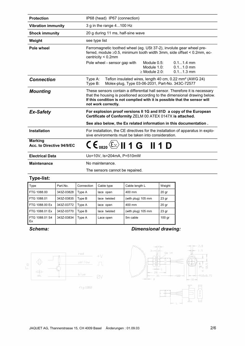
Mounting These sensors contain a differential hall sensor. Therefore it is necessarythat the housing is positioned according to the dimensional drawing below.If this condition is not complied with it is possible that the sensor willnot work correctly.
Ex-Safety For explosion proof versions II 1G and II1D a copy of the EuropeanCertificate of Conformity ZELM 00 ATEX 0147X is attached.
See also below, the Ex related information in this documentation .
Installation For installation, the CE directives for the installation of apparatus in explo-sive environments must be taken into consideration.
MarkingAcc. to Directive 94/9/EC 0820 II 1 G II 1 DElectrical Data Uo=10V, Is=204mA, P=510mW
Maintenance No maintenance.
The sensors cannot be repaired.
Type-list:Type Part.No. Connection Cable type Cable length L Weight
FTG 1088.00 343Z-03828 Type A lace open 400 mm 20 gr
FTG 1088.01 343Z-03835 Type B lace twisted (with plug) 105 mm 23 gr
FTG 1088.00 Ex 343Z-03772 Type A lace open 400 mm 20 gr
FTG 1088.01 Ex 343Z-03770 Type B lace twisted (with plug) 105 mm 23 gr
FTG 1088.01 S4Ex
343Z-03834 Type A Lace open 5m cable 100 gr
Schema: Dimensional drawing:
JAQUET AG, Thannerstrasse 15, CH 4009 Basel Änderungen : 01.09.03 3/6
JAQUET AG, Thannerstrasse 15, CH 4009 Basel Änderungen : 01.09.03 4/6

JAQUET AG, Thannerstrasse 15, CH 4009 Basel Änderungen : 01.09.03 5/6

JAQUET AG, Thannerstrasse 15, CH 4009 Basel Änderungen : 01.09.03 6/6
JAQUET AG, Thannerstrasse 15, CH 4009 Basel Änderungen: 01.09.03 1/6
Ferrostat Differential SpeedProbe Series FTG 1089.XX andEEx-approved Types (atex)
FTG 1089.XXOperating instructions343E-63726
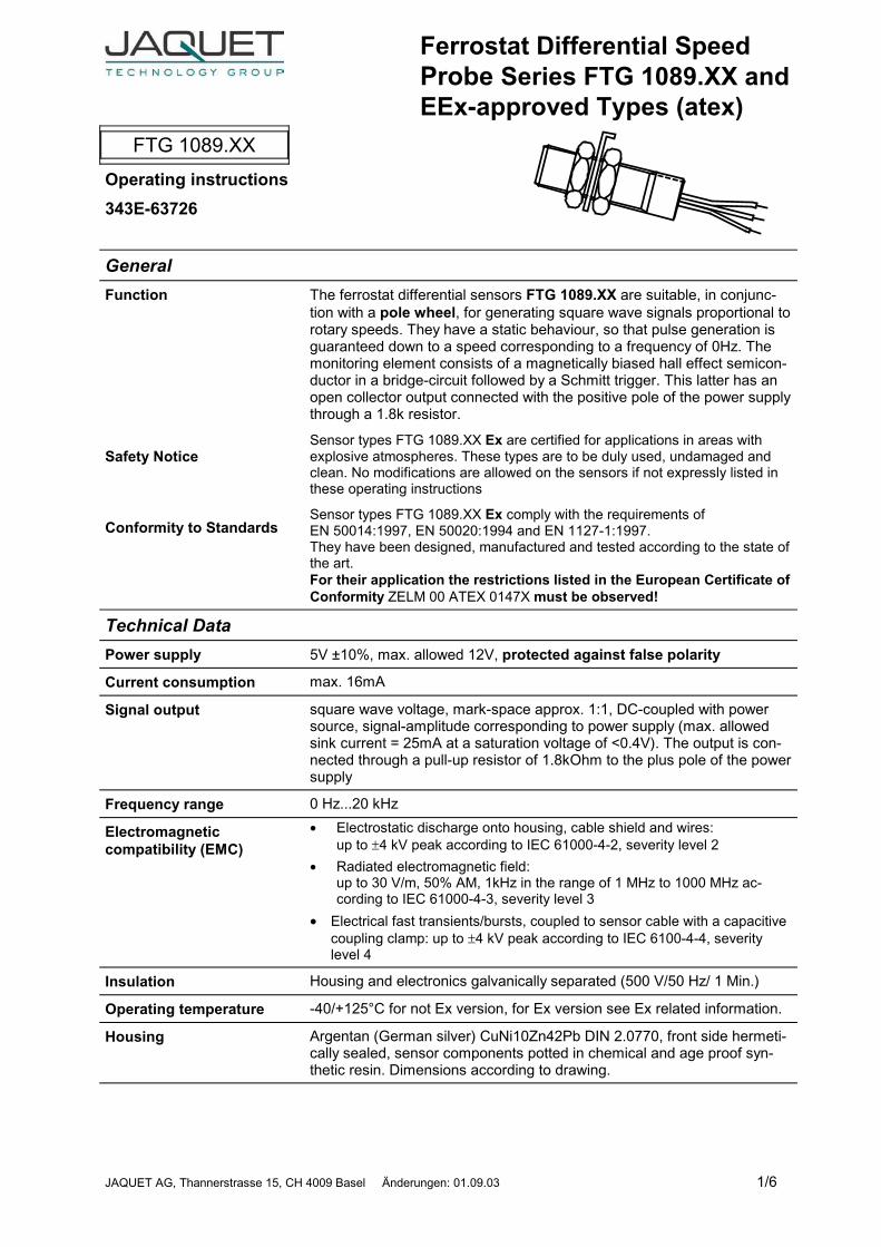
GeneralFunction
Safety Notice
Conformity to Standards
The ferrostat differential sensors FTG 1089.XX are suitable, in conjunc-tion with a pole wheel, for generating square wave signals proportional torotary speeds. They have a static behaviour, so that pulse generation isguaranteed down to a speed corresponding to a frequency of 0Hz. Themonitoring element consists of a magnetically biased hall effect semicon-ductor in a bridge-circuit followed by a Schmitt trigger. This latter has anopen collector output connected with the positive pole of the power supplythrough a 1.8k resistor.
Sensor types FTG 1089.XX Ex are certified for applications in areas withexplosive atmospheres. These types are to be duly used, undamaged andclean. No modifications are allowed on the sensors if not expressly listed inthese operating instructions
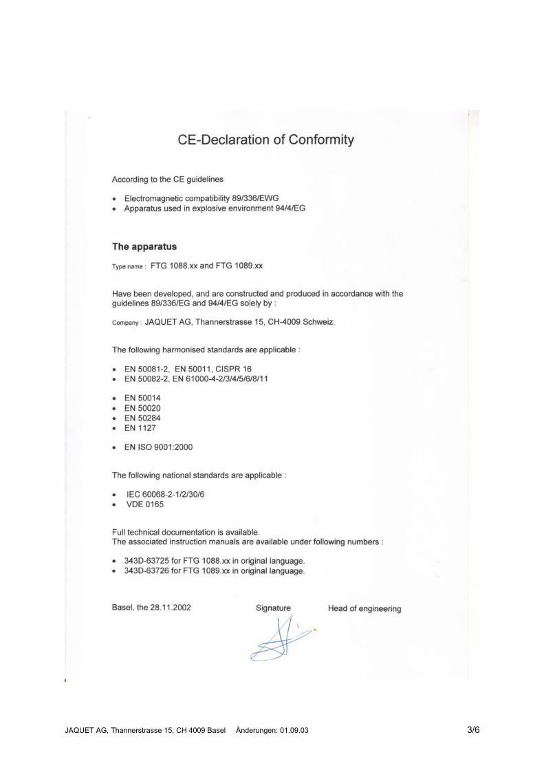
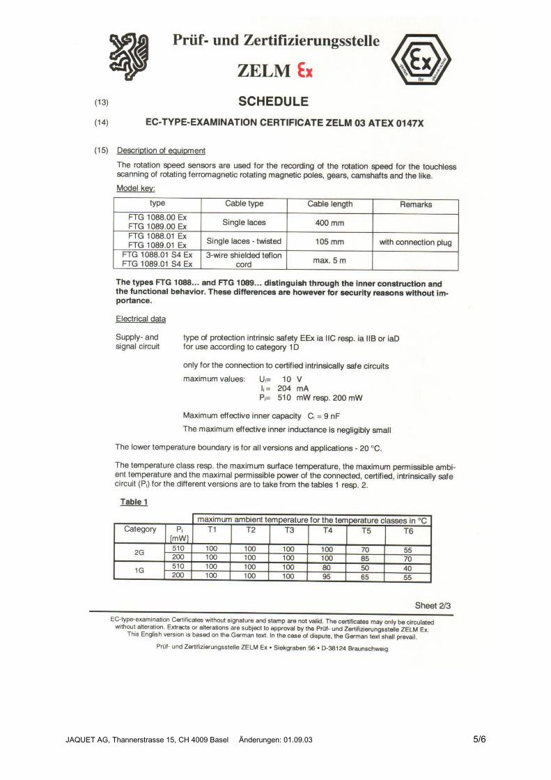
Sensor types FTG 1089.XX Ex comply with the requirements ofEN 50014:1997, EN 50020:1994 and EN 1127-1:1997.They have been designed, manufactured and tested according to the state ofthe art.For their application the restrictions listed in the European Certificate ofConformity ZELM 00 ATEX 0147X must be observed!
Technical DataPower supply 5V ±10%, max. allowed 12V, protected against false polarity
Current consumption max. 16mA
Signal output square wave voltage, mark-space approx. 1:1, DC-coupled with powersource, signal-amplitude corresponding to power supply (max. allowedsink current = 25mA at a saturation voltage of <0.4V). The output is con-nected through a pull-up resistor of 1.8kOhm to the plus pole of the powersupply
Frequency range 0 Hz...20 kHz
Electromagneticcompatibility (EMC)
� Electrostatic discharge onto housing, cable shield and wires:up to �4 kV peak according to IEC 61000-4-2, severity level 2
� Radiated electromagnetic field:up to 30 V/m, 50% AM, 1kHz in the range of 1 MHz to 1000 MHz ac-cording to IEC 61000-4-3, severity level 3
� Electrical fast transients/bursts, coupled to sensor cable with a capacitivecoupling clamp: up to �4 kV peak according to IEC 6100-4-4, severitylevel 4
Insulation Housing and electronics galvanically separated (500 V/50 Hz/ 1 Min.)
Operating temperature -40/+125°C for not Ex version, for Ex version see Ex related information.
Housing Argentan (German silver) CuNi10Zn42Pb DIN 2.0770, front side hermeti-cally sealed, sensor components potted in chemical and age proof syn-thetic resin. Dimensions according to drawing.
JAQUET AG, Thannerstrasse 15, CH 4009 Basel Änderungen: 01.09.03 2/6
Protection IP68 (head)/IP67 (connection)
Vibration immunity 3 g in the range 4...100 Hz
Shock immunity 20 g during 11 ms, half-sine wave
Weight see type list
Pole wheel Ferromagnetic toothed wheel (eg. USt 37-2), involute gear wheel pre-ferred, module �1, minimum tooth width 3mm, side offset < 0.2mm, ec-centricity < 0.2mm,Pole wheel - sensor gap with Module 1: 0.1...0.5 mm
Module 2: 0.1...1.3 mm� Module 4: 0.1...1.5 mm
Connection Type A: Teflon insulated wires, length 40 cm, 0.22 mm² (AWG 24)Type B: Molex-plug, Type 03-06-2031, Part-No. 343C-72577
Mounting These sensors contain a differential hall sensor. Therefore it is necessarythat the housing is positioned according to the dimensional drawing be-low. If this condition is not being complied with it is possible that thesensor will not work correctly.
Ex-Safety For explosion proof versions II 1G and II1D a copy of the EuropeanCertificate of Conformity ZELM 00 ATEX 0147X is attached.
See also below, the Ex related information in this documentation .
Installation For installation, the CE directives for the installation of apparatus in explosiveenvironment must be taken into consideration.
MarkingAcc. to Directive 94/9/EC 0820 II 1 G II 1 DElectrical Data Uo=10V, Is=204mA, P=510mW
Maintenance No maintenance.
The sensors can not be repaired.
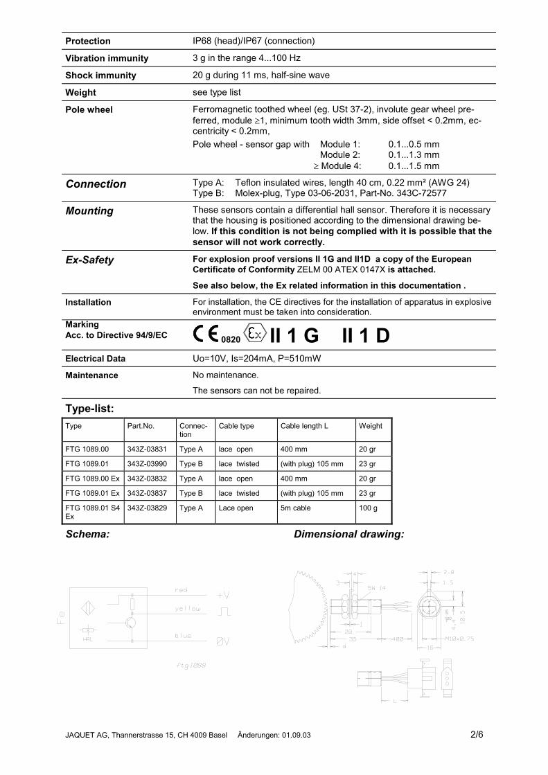
Type-list:Type Part.No. Connec-
tionCable type Cable length L Weight
FTG 1089.00 343Z-03831 Type A lace open 400 mm 20 gr
FTG 1089.01 343Z-03990 Type B lace twisted (with plug) 105 mm 23 gr
FTG 1089.00 Ex 343Z-03832 Type A lace open 400 mm 20 gr
FTG 1089.01 Ex 343Z-03837 Type B lace twisted (with plug) 105 mm 23 gr
FTG 1089.01 S4Ex
343Z-03829 Type A Lace open 5m cable 100 g
Schema: Dimensional drawing:
JAQUET AG, Thannerstrasse 15, CH 4009 Basel Änderungen: 01.09.03 3/6

JAQUET AG, Thannerstrasse 15, CH 4009 Basel Änderungen: 01.09.03 4/6
JAQUET AG, Thannerstrasse 15, CH 4009 Basel Änderungen: 01.09.03 5/6
JAQUET AG, Thannerstrasse 15, CH 4009 Basel Änderungen: 01.09.03 6/6