Davina Ruppal Paveljeet Singh BSc (Hons), MIE C. Engg, FIE ...
24
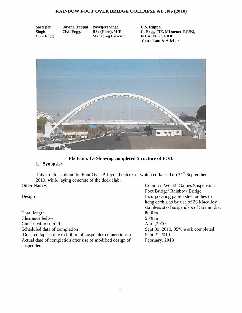
-1- RAINBOW FOOT OVER BRIDGE COLLAPSE AT JNS (2010) Sareljeet Singh Civil Engg. Davina Ruppal Civil Engg. Paveljeet Singh BSc (Hons), MIE Managing Director G.S. Ruppal C. Engg, FIE, MI struct E(UK), FICA, FICC, FIIBE Consultant & Advisor Photo no. 1:- Showing completed Structure of FOB. 1. Synopsis:- This article is about the Foot Over Bridge, the deck of which collapsed on 21 st September 2010, while laying concrete of the deck slab. Other Names Common Wealth Games Suspension Foot Bridge/ Rainbow Bridge Design Incorporating paired steel arches to hang deck slab by use of 26 Macalloy stainless steel suspenders of 36 mm dia. Total length 80.0 m Clearance below 5.70 m Construction started April,2010 Scheduled date of completion Sept 30, 2010, 95% work completed Deck collapsed due to failure of suspender connections on Sept 21,2010 Actual date of completion after use of modified design of suspenders February, 2013
Transcript of Davina Ruppal Paveljeet Singh BSc (Hons), MIE C. Engg, FIE ...
-1-
RAINBOW FOOT OVER BRIDGE COLLAPSE AT JNS (2010)
Sareljeet
Singh
Civil Engg.
Davina Ruppal
Civil Engg.
Paveljeet Singh
BSc (Hons), MIE
Managing Director
G.S. Ruppal
C. Engg, FIE, MI struct E(UK),
FICA, FICC, FIIBE
Consultant & Advisor
Photo no. 1:- Showing completed Structure of FOB.
1. Synopsis:-
This article is about the Foot Over Bridge, the deck of which collapsed on 21st September
2010, while laying concrete of the deck slab.
Other Names Common Wealth Games Suspension
Foot Bridge/ Rainbow Bridge
Design Incorporating paired steel arches to
hang deck slab by use of 26 Macalloy
stainless steel suspenders of 36 mm dia.
Total length 80.0 m
Clearance below 5.70 m
Construction started April,2010
Scheduled date of completion Sept 30, 2010, 95% work completed
Deck collapsed due to failure of suspender connections on Sept 21,2010
Actual date of completion after use of modified design of
suspenders
February, 2013
-2-
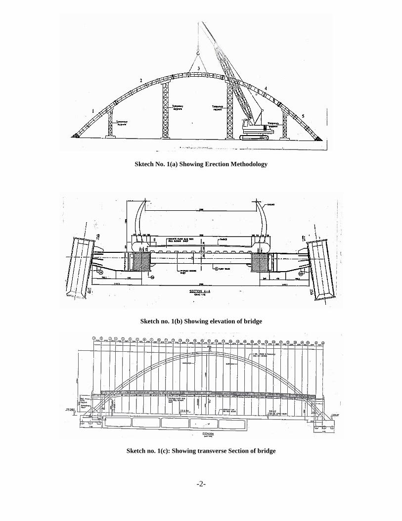
Sktech No. 1(a) Showing Erection Methodology
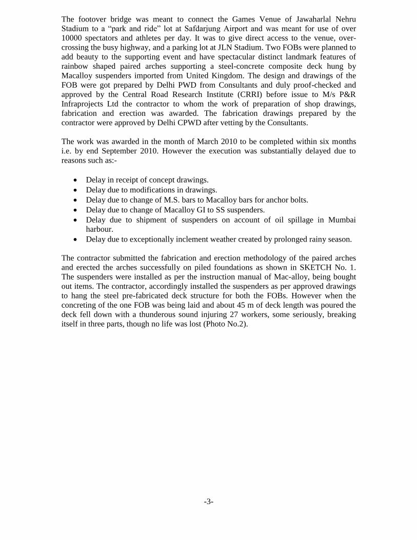
Sketch no. 1(b) Showing elevation of bridge
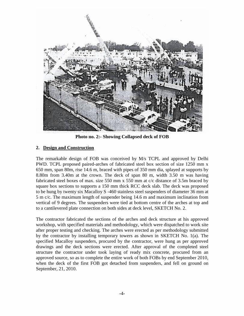
Sketch no. 1(c): Showing transverse Section of bridge
-3-
The footover bridge was meant to connect the Games Venue of Jawaharlal Nehru
Stadium to a “park and ride” lot at Safdarjung Airport and was meant for use of over
10000 spectators and athletes per day. It was to give direct access to the venue, over-
crossing the busy highway, and a parking lot at JLN Stadium. Two FOBs were planned to
add beauty to the supporting event and have spectacular distinct landmark features of
rainbow shaped paired arches supporting a steel-concrete composite deck hung by
Macalloy suspenders imported from United Kingdom. The design and drawings of the
FOB were got prepared by Delhi PWD from Consultants and duly proof-checked and
approved by the Central Road Research Institute (CRRI) before issue to M/s P&R
Infraprojects Ltd the contractor to whom the work of preparation of shop drawings,
fabrication and erection was awarded. The fabrication drawings prepared by the
contractor were approved by Delhi CPWD after vetting by the Consultants.
The work was awarded in the month of March 2010 to be completed within six months
i.e. by end September 2010. However the execution was substantially delayed due to
reasons such as:-
Delay in receipt of concept drawings.
Delay due to modifications in drawings.
Delay due to change of M.S. bars to Macalloy bars for anchor bolts.
Delay due to change of Macalloy GI to SS suspenders.
Delay due to shipment of suspenders on account of oil spillage in Mumbai
harbour.
Delay due to exceptionally inclement weather created by prolonged rainy season.
The contractor submitted the fabrication and erection methodology of the paired arches
and erected the arches successfully on piled foundations as shown in SKETCH No. 1.
The suspenders were installed as per the instruction manual of Mac-alloy, being bought
out items. The contractor, accordingly installed the suspenders as per approved drawings
to hang the steel pre-fabricated deck structure for both the FOBs. However when the
concreting of the one FOB was being laid and about 45 m of deck length was poured the
deck fell down with a thunderous sound injuring 27 workers, some seriously, breaking
itself in three parts, though no life was lost (Photo No.2).
-4-
Photo no. 2:- Showing Collapsed deck of FOB
2. Design and Construction
The remarkable design of FOB was conceived by M/s TCPL and approved by Delhi
PWD. TCPL proposed paired-arches of fabricated steel box section of size 1250 mm x
650 mm, span 80m, rise 14.6 m, braced with pipes of 350 mm dia, splayed at supports by
8.80m from 3.40m at the crown. The deck of span 80 m, width 3.50 m was having
fabricated steel boxes of max. size 550 mm x 550 mm at c/c distance of 3.5m braced by
square box sections to supports a 150 mm thick RCC deck slab. The deck was proposed
to be hung by twenty six Macalloy S -460 stainless steel suspenders of diameter 36 mm at
5 m c/c. The maximum length of suspender being 14.6 m and maximum inclination from
vertical of 9 degrees. The suspenders were tied at bottom centre of the arches at top and
to a cantilevered plate connection on both sides at deck level, SKETCH No. 2.
The contractor fabricated the sections of the arches and deck structure at his approved
workshop, with specified materials and methodology, which were dispatched to work site
after proper testing and checking. The arches were erected as per methodology submitted
by the contractor by installing temporary towers as shown in SKETCH No. 1(a). The
specified Macalloy suspenders, procured by the contractor, were hung as per approved
drawings and the deck sections were erected. After approval of the completed steel
structure the contractor under took laying of ready mix concrete, procured from an
approved source, so as to complete the entire work of both FOBs by end September 2010,
when the deck of the first FOB got detached from suspenders, and fell on ground on
September, 21, 2010.

-5-
SKETCH No. 2: Transverse Sectional Elevation at Crown of Arch
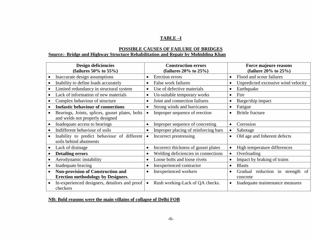
3. Possible causes of failure of bridges
As per recent international studies it has been established that major bridges keep on
failing and collapsing, around the globe, with a frequency of 30 years, causing loss of life
and humiliation to the engineers due to the three main reasons, out of the all possible
reasons, as enumerated in TABLE No. I, namely:-
Design deficiencies
Construction errors
Force- majeure, natural phenomena and extreme events
Records also show that fifty percent of failures are attributed to design deficiencies and
Twenty Five Percent each to construction errors and natural causes, respectively.
-6-
TABLE –I
POSSIBLE CAUSES OF FAILURE OF BRIDGES
Source:- Bridge and Highway Structure Rehabilitation and Repair by Mohiddina Khan
Design deficiencies
(failures 50% to 55%)
Construction errors
(failures 20% to 25%)
Force majeure reasons
(failure 20% to 25%)
Inaccurate design assumptions Erection errors Flood and scour failures
Inability to define loads accurately False work failures Unpredicted excessive wind velocity
Limited redundancy in structural system Use of defective materials Earthquake
Lack of information of new materials Un-suitable temporary works Fire
Complex behaviour of structure Joint and connection failures Barge/ship impact
Inelastic behaviour of connections Strong winds and hurricanes Fatigue
Bearings, Joints, splices, gusset plates, bolts
and welds not properly designed
Improper sequence of erection Brittle fracture
Inadequate access to bearings Improper sequence of concreting Corrosion
Indifferent behaviour of soils Improper placing of reinforcing bars Sabotage
Inability to predict behaviour of different
soils behind abutments
Incorrect prestressing Old age and Inherent defects
Lack of drainage Incorrect thickness of gusset plates High temperature differences
Detailing errors Welding deficiencies in connections Overloading
Aerodynamic instability Loose bolts and loose rivets Impact by braking of trains
Inadequate bracing Inexperienced contractor Blasts
Non-provision of Construction and
Erection methodology by Designers.
Inexperienced workers Gradual reduction in strength of
concrete
In-experienced designers, detailors and proof
checkers
Rush working-Lack of QA checks. Inadequate maintenance measures
NB: Bold reasons were the main villains of collapse of Delhi FOB
-7-
4. Enquiry committees for collapse of FOB
Immediate on collapse of the FOB the NCR-Delhi Government constituted two
committees to enquire into the causes of the failure, to pin point the responsibilities and
to suggest measures to avoid recurrence of such incidences as under:-
Technical Investigations (Dogra
committee)
Comprising of Er. HM Dogra ex. DG of
CPWD and Dr. Ashok Gupta of IIT Delhi
Forensic Investigations The Delhi Police crime branch appointed
IIT Roorkee to conduct forensic
investigation who detailed Dr. Bhupender
Singh and Dr. Vipul Parkash to deal with
the case.
Of their own the contractors, M/s P&R Infraprojects Ltd, appointed the following three
independent and reputed agencies to conduct the technical investigations of failure:-
PRABHU STRUCTURALS
Consultant & Engineers – N. Delhi
Futura Design Consultants Pvt. Ltd. – Ludhiana
Kiri Associates Pvt. LTd. Consultants, Architects, Engineers & Builders – N.
Delhi
All the three above agencies are well experienced in conceptualization of shapes,
designing, drawings, construction and supervision of all types of steel and concrete
bridges including suspension bridges and FOBs.
All enquiry committees visited the site of the accident, collected samples of materials,
took photographs, took statements of the representatives of the TCPL, PWD engineers,
contractors representatives and workers and also collected copies of the relevant
documents in regard to design, drawings, MTRS, construction methodology, QA reports
etc. etc. as deemed necessary for in depth study of the case.
-8-
4.1 Reports of Enquiry committees and private consultants.
Firstly the contractor received the technical reports of the three independent Consultants
appointed by him which were forwarded to the two committees appointed by the Delhi
PWD. These Consultants reported the following causes of the collapse:-
Brief of Report of PRABHU STRUCTURALS:-
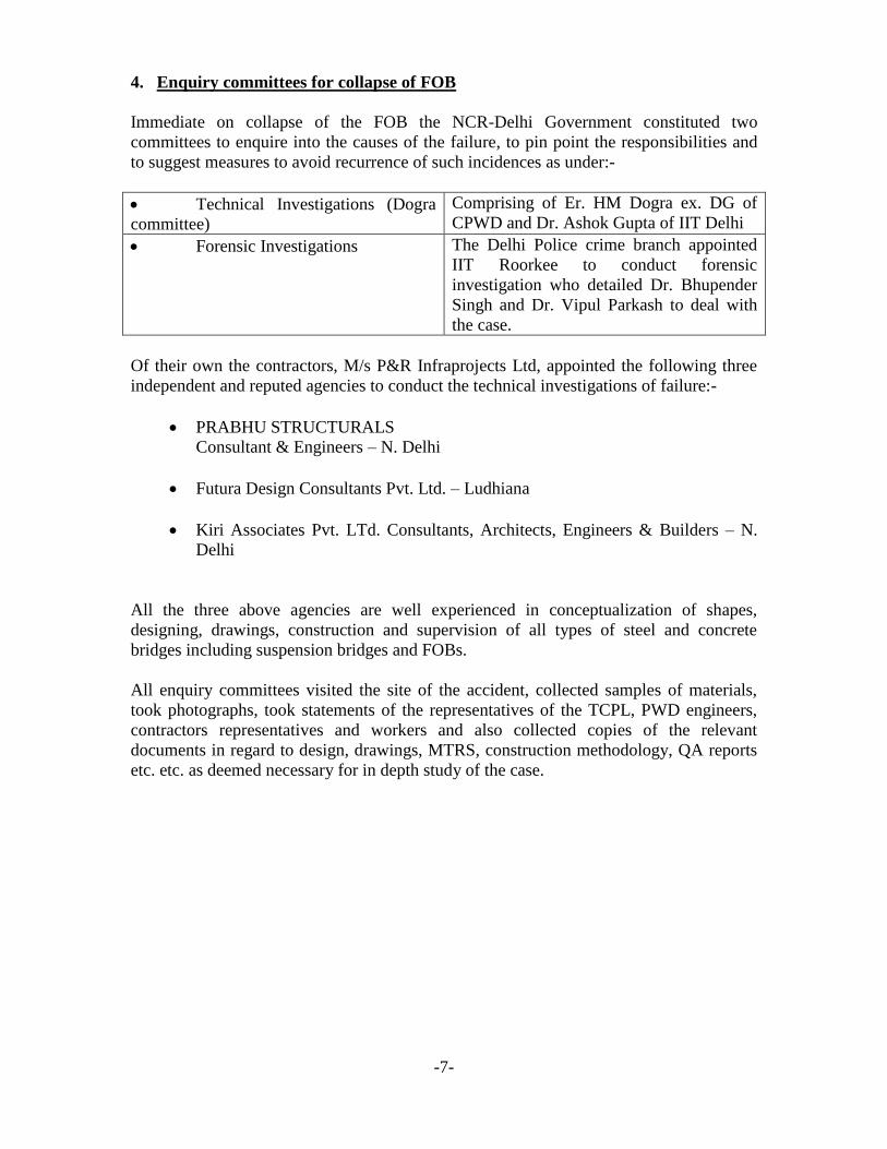
1. It is obvious that the suspension fork and pin have given way because the pin has been
detailed by the designer perpendicular to the axis of the bridge which restricted the
movement of the suspender around the pin to cater to the changing deflection caused by
the loading. The eye lets of the fork opened out due to inadequate fastening/ locking of
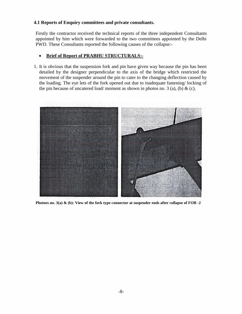
the pin because of uncatered load/ moment as shown in photos no. 3 (a), (b) & (c).
Photoes no. 3(a) & (b): View of the fork type connector at suspender ends after collapse of FOB -2
-9-
Photo no. 3(c): Bending of the arm of the fork type connector was seen in almost all the suspender
rods retrieved from the site.
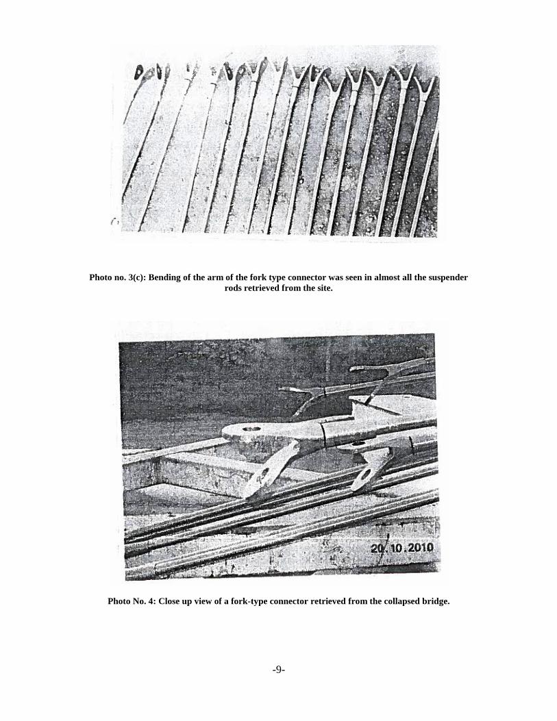
Photo No. 4: Close up view of a fork-type connector retrieved from the collapsed bridge.
-10-
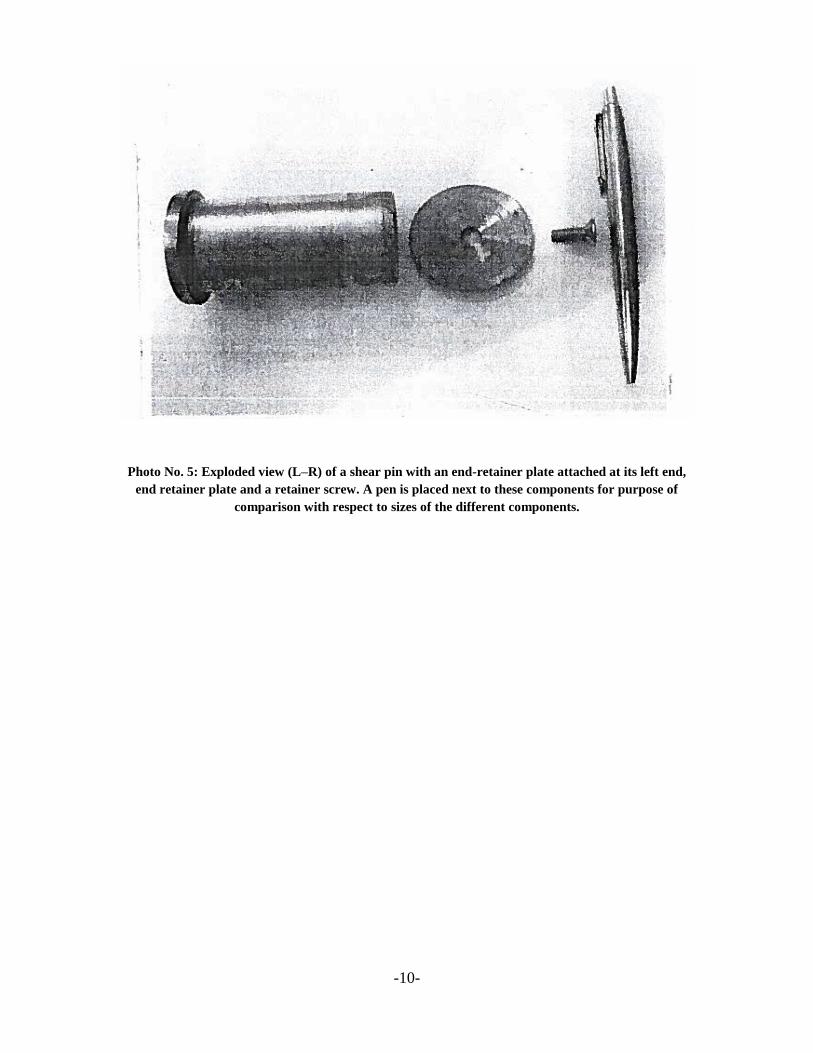
Photo No. 5: Exploded view (L–R) of a shear pin with an end-retainer plate attached at its left end,
end retainer plate and a retainer screw. A pen is placed next to these components for purpose of
comparison with respect to sizes of the different components.
-11-
2. To provide a welded cleat connection of ISAs to the box girder, in the cantilever
portion to hang the suspenders, with fillet welds at 144 mm distance, as shown in
SKETCH No. 2 is a very wrong idea which was subjected to bending moment over
and above the shear force. The welds were subjected to heavy impact load when the
bridge fell and hit the ground damaging connections
On the whole the bridge collapsed on account of the above said points and express the
want of correct designing of the details of the joints whether it is a suspension or a girder
bridge
4.2 Report of Futura Design Consultants Pvt. Ltd.:-
The following design inadequacies were observed in the FOB of JNL Stadium:-
1. Restriction to Thermal Expansion/ Moment:-
There is no scope for movement due to thermal expansion/ contraction at
support locations. The deck should be provided with bearings at location of
crossing of the arch or at the ends where it is supported on columns or both
locations. However it has been bolted at columns locations, which has arrested
the scope of movement & builds stresses in the structure, which are avoidable.
On the contrary, the deck has been welded to the arch and its movement
therefore is restrained, which is very unusual for particularly long span bridge,
where the movement from centre will be of the order of 40 mm (+20/-20mm) on
either side.
2. Rigidity vs flexibility
The arrangement of deck provided i.e. suspended with hangers is essentially a
flexible structure, has been contradicted by detailing. Providing a very rigid deck
truss and restraining its movement at ends at arch & deck made by providing
forks in perpendicular direction it rigid structure, the detailing does not leave any
scope for rotation at ends in transverse direction, the basic purpose of provision of
fork end arrangement at hanger ends both at arch & deck is defeated. The deck
grid structure has been made very rigid.
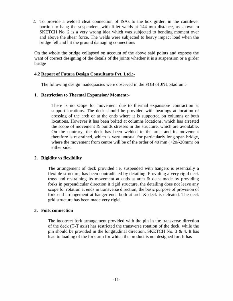
3. Fork connection
The incorrect fork arrangement provided with the pin in the transverse direction
of the deck (T-T axis) has restricted the transverse rotation of the deck, while the
pin should be provided in the longitudinal direction, SKETCH No. 3 & 4. It has
lead to loading of the fork arm for which the product is not designed for. It has
-12-
caused failure/ bending of the fork arm, hence the pin and thus the bridge. It is
clear from the failure pattern of different hangers shown in photo 3 & 4.
SKETCH NO. 3: Typical arrangement of a fork-type connector and names
of its parts.
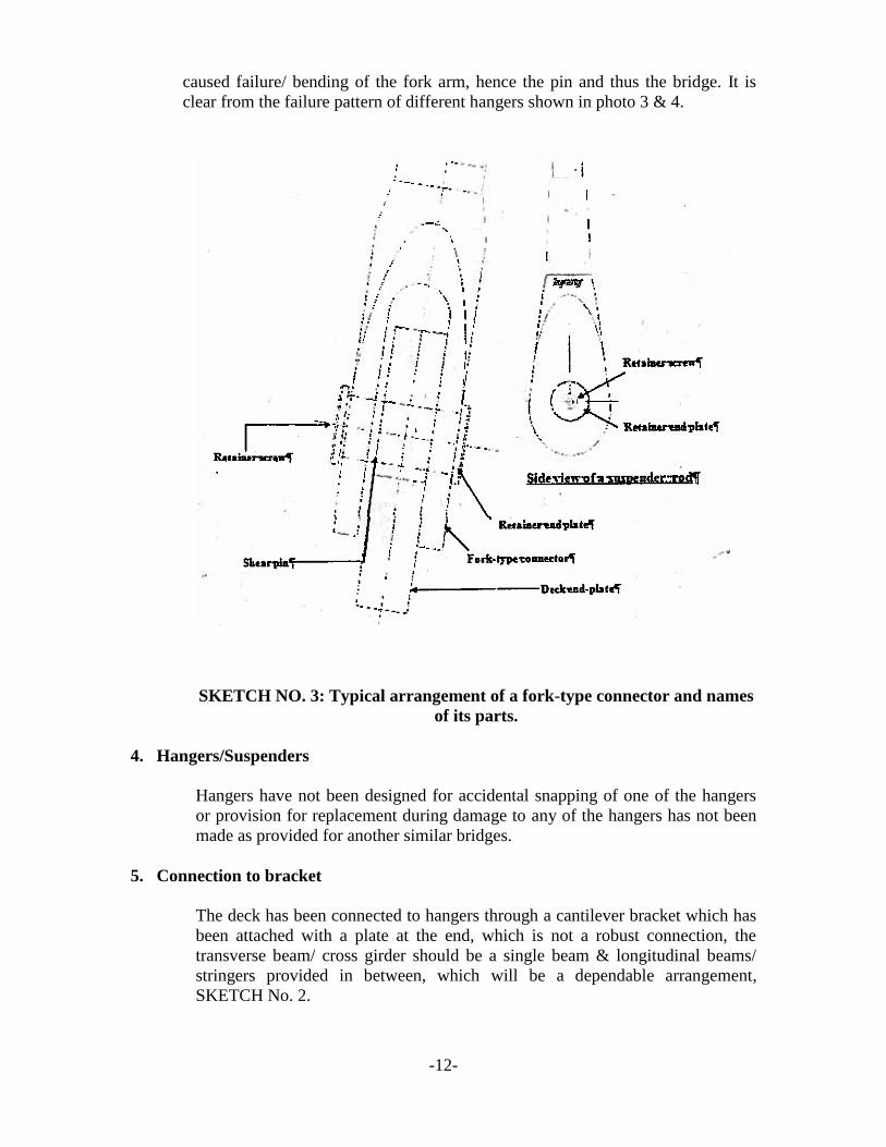
4. Hangers/Suspenders
Hangers have not been designed for accidental snapping of one of the hangers
or provision for replacement during damage to any of the hangers has not been
made as provided for another similar bridges.
5. Connection to bracket
The deck has been connected to hangers through a cantilever bracket which has
been attached with a plate at the end, which is not a robust connection, the
transverse beam/ cross girder should be a single beam & longitudinal beams/
stringers provided in between, which will be a dependable arrangement,
SKETCH No. 2.
-13-
6. Erection Methodology
The drawings do not indicate erection methodology required to be adopted for the
bridge, which is a must for such state of the art structure.
7. Example of Road Bridge
Reference may be made to bridge on NH – 21, bridge, designed by CES, where two
sets of hangers have been provided to allow transverse rotation of the deck. The
direction of provision of plate is facing the direction of traffic, the pin being in the
direction of the traffic. Also double set of hangers has been provided to allow easy
replacement of hangers and also accidental snapping of one of the hangers. Also this
transverse girder has been provided as single beam which is main connection with the
hanger rather than depending upon a bracket connection for main load carrying
member.
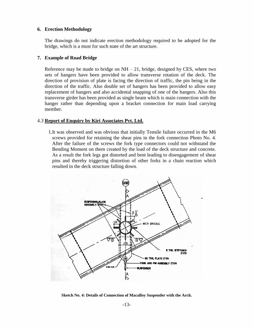
4.3 Report of Enquiry by Kiri Associates Pvt. Ltd.
1.It was observed and was obvious that initially Tensile failure occurred in the M6
screws provided for retaining the shear pins in the fork connection Photo No. 4.
After the failure of the screws the fork type connectors could not withstand the
Bending Moment on them created by the load of the deck structure and concrete.
As a result the fork legs got distorted and bent leading to disengagement of shear
pins and thereby triggering distortion of other forks in a chain reaction which
resulted in the deck structure falling down.
Sketch No. 4: Details of Connection of Macalloy Suspender with the Arch.
-14-
2. As per design calculations of TCPL the suspenders are subjected to a maximum
load of 14.6 Tonne in worst scenario. The suspenders being hung at an angle of 9
degrees to the vertical could have generated a horizontal force of 2.284 tonue on the
fork legs when subjected to this load. This horizontal force is transmitted to the
screw M – 6 (4.5mm nominal rod diameter) and a Bending moment in the fork for
which these were not designed. The Retainer screws M-6 have a rated Tensile
Breaking strength of 0.667 Tonne and will fail at appreciably less than the 2.284
Tonne load that they could be subjected to at the Maximum Loading. Accordingly
after Tensile failure of the retainer screws, the two legs of the fork type connectors
got splayed and became independent of each other, and Bending Moment caused
one or both the legs to bend outwards and disengage from the shear pin, resulting in
total lack of support for the Deck structure as show in Photo No. 3.
3. During observation at site no defect in materials used and workmanship could be
found.
4. There is no doubt whatsoever about the fact that the failure occurred primarily due
to ignorance, inexperience and gross negligence on the part of the Designers and the
Approving Authority.
4.3.1 Report of Dogra Committee appointed by Delhi – PWD (As per PTI release)
The panel, set up to probe the collapse of the foot over bridge near JN Stadium
just before the Commonwealth Games, has blamed PWD for “supervisory
failures” while it held P&R Infraprojects Ltd for carrying out the project in a great
hurry as reported in a newspaper release:-
According to the official release, the panel has pointed out that the design
consultant M/s TCPL did not give the methodology of construction and the
contractor devised the procedure on its own without taking any necessary
approval. Sources said that since the project had to be completed within one
week, the contractor did not submit any construction methodology and it never
came up for approval. PWD officials said that the contractor was not a „novice‟
since it had executed major projects by then.
The release said, “As per the report, the cause of the collapse could be
asymmetrical loading more than permissible level which resulted into over-
stressing of Maccalloy joint connecting the deck slab with the Macalloy
suspenders that were imported from UK. The committee also brought out that
while fabricating the deck, a slightly thicker gusset plate was used due to non
availability of the recommended size. “We had little time, so we went for slightly
thicker gusset plates. But those were manufactured by the best companies,” a
senior PWD official said.
The report said that UK firm M/s Macalloy which supplied the suspenders had
said after the incident that it felt “the orientation of the gusset plate was in the
wrong plane.” However, no such observations were made by them when the
-15-
drawings were forwarded to them in April 2010 by the contractor for fabrication
of the system. When asked by the probe committee to clarify why this suggestion
was not given in April 2010, M/s Macalloy have not provided any response,
government said.
NONE TO BLAME: PWD official said that the contractor was not a „novice‟
since it had executed many other major projects.
44.1 Report of Forensive Investigation Team
The Delhi Police crime branch was assigned to conduct forensic investigations in
association with IIT Roorkee in regard to the general and standard aspects of:-
Expert interviews of witnesses.
Checking technical aspects like knowledge, experience and competency of
consultant, contractor and client.
Use of detective skills to check the quality of materials used, tampering of samples,
authenticity of records, sabotage, mischief, pilferage, hiding and altering records
etc.
Legal aspects of the damage caused.
Work place safety and liability.
Compliance with codes.
Corruptive practices.
Causes of failure as the primary objective
The Police Department did not find any of the above defects but came to a
unsubstantiated conclusion that the collapse occurred due to lack of suspervision and
hasty execution of works. The injured persons were suitably compensated as per
directions of the Honble Court by the contractor.
4.4.2 Report of Collapse of the Foot Bridge by Department of Civil Engineering IIT
– Roorkee:-
As a consequence of detailed examination of the fallen bridge structure, design
calculations, proof checking, construction methodology adopted, the quality of materials
used, quality assurance systems observed and work site supervision aspects the IIT
Roorkee submitted its report with the following predominant and important observation:-
(a) The IIT Roorkee observed the following nine deficiencies in design of the
bridge:-
-16-
DEFICIENCY : 1 It is not understood why the suspenders are provided at a longitudinal c/c spacing of 5.0 m i.e. at
locations of alternate X-girders, rather than at 2.5 m intervals, i.e. at the locations at which the X-
girders have been provided both in the arch and in the lateral steel floor truss carrying the RCC
deck slab.
DEFICIENCY : 2 It is not understood why the suspenders had to be stainless steel bars, M36 Macalloy S460
Stainless steel bar system (including and forks & pins) or equivalent and capable of in-situ length
adjustments using end-forks to be procured from specialist supplier.
DEFICIENCY : 3 It is not understood why the structural designer did not choose to shorten the gravity load path
and make it more robust.
DEFICIENCY : 4 It is not understood why the structural designer chose to provide the cantilever brackets.
DEFICIENCY : 5 The x-section of the cantilever bracket and the X-girder between the L-girders are sized
disproportionately to the design requirement.
DEFICIENCY : 6 The X-girders between the L-girders are considered as hinged at their connections with L-girder
in STAAD computer analysis.
DEFICIENCY : 7: The site splice detail between arch segments appears to be incapable of transmitting bending
moments from one segment to the other, except small amount due to friction and pre-tension of
the bolts.
DEFICIENCY : 8 The 8 mm thick chequered plate is too thick from any design considerations or from
considerations of good engineering practice.
DEFICIENCY : 9 It is nor understood that when steps and landings in the staircases leading to the bridge could be
in steel, why a similar steel deck not deemed suitable for the bridge. What was the necessity of
providing a much heavier 150 mm thick RCC deck slab.
(b) Based upon the impact of the nine design deficiencies and the mode of failure
taken place during collapse of the bridge the IIT Roorkee gave the Conclusion as
under:-
Conclusion by IIT Roorkee:-
Nine critical deficiencies in the structural design were identified, reasons for considering
them as deficiencies were provided, and better design alternatives were also suggested.
This way of presentation was chosen to facilitate the structural designer in providing the
needed clarifications to dispel there deficiencies.
-17-
Without the needed clarifications, it can be concluded that all these deficiencies arose
owing to short- circuiting of the structural design process by the designer of the bridge,
who chose to omit the preliminary analysis and design phase. Owing to this omission, the
designer failed to visualize the gravity and lateral load paths for this structure.
Consequently computer analyses was carried out based on wrong design decisions,
reflected in Deficiencies 1, 3, 4, 5, 6 and 9, which became the basis for an uneconomic
and unsafe design. Deficiencies 2 and 8 especially show that the designers were not
sensitive towards achieving an economical design outcome.
Preliminary analysis and design was to be carried out manually and members and their
connections were to be designed in the sequence dictated by the load paths, which are
shown in (SKETCH – 4) for this bridge. This preliminary analysis and design document
was to be submitted along with computer analysis and design notes and drawings for
proof checking the design. Only then proof-checking could and should have been ideally
carried out.
The preliminary analysis and design document could and should also have been checked
by the government department entrusted with the task of getting a public facility
constructed, so as to ensure an economical and safe structure. This checking would also
have equipped the government department with the understanding needed to supervise
the construction of the bridge with the needed quality control at the site. This checking
would also have enabled the government department with the understanding needed to
maintain the structure during its service life.
These deficiencies resulted in an unsafe as-well-as an uneconomical bridge, which
collapsed while it was being constructed.
Owning to deficiencies 1 and 9, the bridge was especially vulnerable to progressive
collapse on failure of a single suspender, which could have occurred at any time during
the service life of the bridge.
The post collapse evidence was reviewed. It was concluded that a progressive collapse
occurred due to the failure of “Architectural” components in the fork-type connectors at
the ends of suspenders Photo – 3. This progressive collapse of the bridge was aided by
the heavy RCC deck slab (Deficiency 9), and the larger suspender spacing chosen by its
designers (Deficiency 1).
The unwarranted choice of the Macalloy stainless steel bars as suspenders is specified in
the General Arrangement Drawing (Deficiency 2). As per product technical approval
document available on Macalloy‟s internet website, the chosen product was suitable only
for predominantly static loads, and not for sudden or impact loads, nor for systematic
bending. Further, the product needed to be accessible in order to facilitate replacement of
individual components at any time.
The above conclusion almost matches with the findings of the other Consultants and
Committees as narrated above.
(c) As regards review of the Construction aspects the IIT Roorkee opined as under:-
-18-
The arches were to be erected in a total of five segments and the erection methodology
proposed by the contractor of the bridge was found to be satisfactory. A perusal of site
records made available to the technical team indicates that a reasonable quality control
system related to the various construction activities was in place at site. As part of quality
control, regular third party testing of steel, paint and welding consumables has been
carried out during the course of the bridge construction and the material test reports
indicate compliance with specifications and have been seen to be compiled in a proper
manner and are available for ready inspection. It is noted that the paints have been
sourced from a reputed manufacturer like AkzoNobel and welding consumables were opf
Esab make, another reputed supplier. The test reports show that the medium and high
strength micro alloyed structural stele was sourced from Steel Authority India Ltd. a
known manufacturer of such material. TATA steel supplied the hot rolled coils for the
bridge. The test results of the high yield strength steel reinforcement bars of 16 mm and
20 mm diameter indicate compliance with requirements of IS: 1786-2008.
Records of site inspection reports related to Fit-up, welding and painting processes during
fabrication of the arch segments and the deck have been maintained at site and upon
review were found to be satisfactory. The ultrasonic test reports made available to the
technical team do not indicate any distress in the welded joints or the steel plates which
were subjected to testing in the bridge structure.
A review of the quality management in the construction of the FOB – 2 indicates that the
quality assurance and the quality control techniques were reasonably commensurate with
the scale of the project though greater involvement of site representatives of the client in
the quality management would have been desirable. A majority of the quality control
reports indicate the complete absence of first party, i.e. the client. Therefore, there is no
independent check on the activities of the second party, i.e. the contractor, and the third
party i.e. the testing agency in the quality control process.
5. Macalloy SS Suspenders S – 460:-
Macalloy Prefabricated Tension Rod System. The European Technical Approval for the
stainless steel tension rod systems specifies as under:-
The tension rod systems are intended for the use in structures with predominantly static
loads
The tension rod systems are not subjected to systematic bending.
Design is carried out by the designer of the structure experienced in the field of steel
structures.
All the above important stipulation were contradicted by the Designers of the Foot Over
Bridge.
6. Mode of Collapse
The eye witnesses including workers engaged for concreting of the deck slab, reported
that the concreting of the deck was started in the noon of September 21st by pumping of
-19-
readymix concrete from the road side. When about 50 m of the deck length was concreted
they felt some sudden jerks sounding as “Karakk” and the deck slightly vibrated. Soon
two of the suspenders at middle of the span suddenly snapped, shaking the bridge
vigorously and triggering a chain reaction of snapping of all suspenders of both sides.
The deck broke in three pieces and fell on ground with a thud shaking the ground like a
mild earth quake. Some of the workers jumped off the bridge and others fell down
alongwith the deck. Fortunately none was buried under the fallen bridge parts. The
workers on the ground fled away as soon as they heard the sound of snapping of
suspenders, shaking of the deck, cries of the workers and falling of the deck.
7. Actual Cause of Collapse of Deck Slab:-
The undisputable cause of collapse, as indicated in the various Enquiry Reports, and
studied by the authors, is tensile failure of the Retainer Screw of M -6 (Nominal rod
diameter 4.5 mm) due to Bending moment caused in the Fork legs due to inclination of 9
degrees of the suspender and incorrect orientation of the Fork/ pin as shown in SKETCH
– 4).
Due to inclination of the suspenders by 9 degrees to the vertical a horizontal force of
about 1108 Kgs was generated and imposed on the leg of the fork of size 6.5 cm x 1.5 cm
at the critical section due the dead weight of the steel deck, concrete laid, construction
load and self loads of the suspender. This horizontal load subjected the leg of the fork to a
Bending Moment of 1108 x 14 = 15512 Kgcm while the moment of resistance of the fork
leg was only 11213 Kgcm. The excessive bending moment transmitted a tensile force of
1108 Kgs on the washer of the pin which was further transmitted to the restraining M-6
screw which could sustain a force of only 574 Kgs only. The screw broke away by
elongation, popped away disconnecting the suspenders from the deck, triggering a chain
reaction of failure of all other succeeding and proceeding suspenders and falling down of
the deck breaking in three pieces. The edges of the end pieces of the deck struck the
ground on one end thus causing impact waves which damaged the connections and
cantilevers. The central portion fell upon the road central verge and broke in two pieces
as shown in Photo No. 2.
It is worthwhile to pinpoint that some other minor deficiencies in construction, as brought
out by the consultants had no role to play in the collapse of the bridge as these were not
found to be damaged after the collapse.
8. Inaccuracies in the Enquiry Report of the Dogra Committee:-
The report is technically correct as far as the reason of collapse is concerned which is
attributed to the asymmetrical loading more than permissible level which resulted into
over stressing of Macalloy joint connecting the deck slab with Macalloy suspenders due
to wrong orientation, that were imported from UK. However the authors differs with
other contents of the report as follows:-
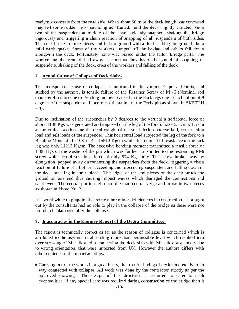
Carrying out of the works in a great hurry, that too for laying of deck concrete, is in no
way connected with collapse. All work was done by the contractor strictly as per the
approved drawings. The design of the structures is required to cater to such
eventualities. If any special care was required daring construction of the bridge then it
-20-
was mundane for the Consultants to mention such cautions in the construction drawings
and to be pointed out during routine site visits. Hind sight unsubstantiated comments
are condemnable.
The contractor did submit a detailed methodology for his work of fabrication and
erection of the arches upon which no objections were communicated by the Owner.
No methodology for installation of suspenders was necessary to be submitted by the
contractor because being bought out items from the specified source the suspenders
were to be installed as per manual of the supplier and drawings issued by the Delhi
PWD under their supervision.
Use of a slightly thicker plates, which were rolled within the permissible limits of
thickness for the gussets was in no way responsible for collapse or any other
eventuality. However such eventualities are required to be catered in the design
calculations and drawings.
The contractor did raise questions of deficiencies in design pin-pointing wrong
orientation of the fork and the pin, the wrong fixity at both ends of the bridge and
wrong welding of the deck with the arches at the meeting points etc. etc. during routine
meetings with the owner and Designers.
Fairly and squarely the Designers were responsible for the collapse of the deck structure.
The contractor followed best construction practices and is in no manner blame-worthy.
Had the orientation of the fork pin kept in the direction of the deck collapse all the fuss
made would have not happened.
9. Comments on Design Aspects of the foot over bridge as per the study of the
authors:-
Failures are open books. The causes of failures can be accurately ascertained by checking
of any design deficiencies, construction errors, use of bad materials, wrong application of
new technologies, supervisory glitches and natural calamities etc. In this case there were
several design deficiencies which lead to collapse such as:-
Wrong application of the Macalloy 460 –S suspenders of 36 mm diameter against the
instruction of the European Technical Approval.
Wrong use of the suspenders which are meant for only static loads and not dynamic
loads.
Wrong orientation of the fork connection for a bridge which is subjected to dynamic
loading.
Wrong end connections of the suspenders with the box girder by providing a
cantilevered cleat connection in lieu of simple bolted connections.
-21-
Splaying the arches from c/c distance of 2.4 m at crown to c/c distance of 8.80m at the
end supports on foundation was wrong which resulted in inclination of suspenders. Had
the suspenders been vertical there could have been no Bending moment on the fork
connection suspenders.
Restrictions created by welding of the deck with the arches, at the deck level, and fixing
the ends by anchor bolts to absorb the thermal expension and moments was against
normal practice.
The arrangement of the suspended deck with suspenders is essentially a flexible
structure which has been made rigid in detailing. The basic purpose of the fork
connection was defeated.
The detailed design of the joint of Macallay suspender with the deck of FOB in terms
of asymmetrical loading and rotation of the gusset plate was not done.
The consultants very well realized the mistake of using of a pin connection as seen
from the design of connections of the other similar bridges, designed after collapse of
this bridge, where nut-bolt replaced the pin connection.
Due to the above in-herent design deficiencies, inaccurate assumptions, lack of
experience of use of new materials and technology, inelastic behaviour of connections,
detailing errors and inexperience of detailor the FOB was bound to collapse sooner or
later. Had the deck collapsed when under use of the spectators and athletes it would have
resulted in catastrophy of gargantuan nature bringing national shame and possible fall of
the governments!
10. Pinning Responsibility of collapse
Modern bridge architecture is any thing but a breeze. The Designers and Architects keep
on evolving new novel shapes and sizes which when accomplished become land marks.
Modern bridges depict cultures and social ethos of the countries. Sydeny-Australia is
known for its Darling Horbour Bridge, New York is known for George Washington
Bridge, London is known for its Tower Bridge and Millenium Foot Over Bridge,
Mumbai is known for its Mumbai- Sea link bridge and Kolkatta is known for its Howrah
Bridge. Innovations are always risky but without risk we don‟t advance. At the cutting
edge, uncertainty is an occupational hazard.
Though the design of the FOB, for main elements, was found to be over-designed, but
errors crept in due to faulty connection details of suspenders. Such errors inadvertently
occur in designs for which proof checkers are appointed. In this case the fault equally lies
with the Designers as well as the proof checkers, who failed in detecting and pointing out
the detailing deficiencies.
11. Reconstruction of the Foot Over Bridge
The foundations and the paired arches of both the FOBs, costing about 70% of the total
price of the bridges, were safe, sound and intact. The deck structure of one FOB was also
-22-
intact on which concrete was not laid. Due to collapse of the deck structure of one FOB
60% reinforced concrete laid on it were lost.
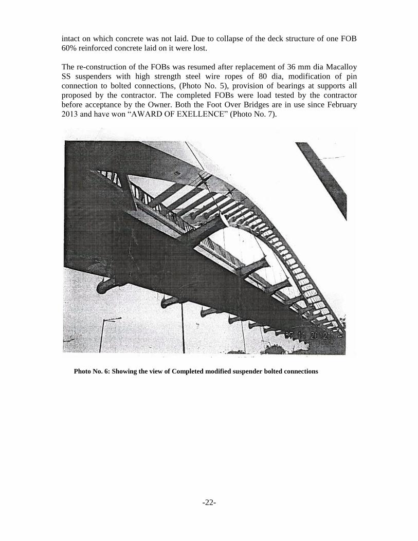
The re-construction of the FOBs was resumed after replacement of 36 mm dia Macalloy
SS suspenders with high strength steel wire ropes of 80 dia, modification of pin
connection to bolted connections, (Photo No. 5), provision of bearings at supports all
proposed by the contractor. The completed FOBs were load tested by the contractor
before acceptance by the Owner. Both the Foot Over Bridges are in use since February
2013 and have won “AWARD OF EXELLENCE” (Photo No. 7).
Photo No. 6: Showing the view of Completed modified suspender bolted connections
-23-
12. Media Report:-
On occurrence of such construction failures the country most active media
immediately cries for throat of the contractor which is unethical and immoral because
it causes immense harm to the reputation of the contractor who may be innocent. The
responsibility of failure can be pin-pointed only after the actual causes of failure are
ascertained after thorough investigations.
13. Lessons Learnt:
Bridge building is a risky business. Absolute safety for the design and
construction of the bridges is unattainable. The risks of unintended and unwanted
events are always present, but forewarned is forearmed. Use of new technologies
and new materials necessitates thorough checks to ensure that the designs,
drawings and detailing are correctly prepared to avoid loss of lives, interruption of
traffic, costly repairs and replacements.
The proof checking of designs should be assigned only to reputed experienced
and competent consultants.
The well experienced fabricators and erectors should be consulted by the Bridge
Designer, to devise construction and erection methodologies which should be
invariably be provided in the Construction Drawings.
Adequate attention should be paid to accuracy of design parameters and
assumptions, temporary erection arrangements and erection methodology,
construction crew and competency of supervisory personnel and consultants.
The suppliers of sophisticated materials of new technology like anchors,
suspenders, hangers, bearings, expansion joints, prestressing materials and
equipment membrane, roof sheeting, admixers, formwork, cranes, special paints,
and lifting equipment etc. etc. should be consulted for complex bridge projects
and new technologies.
Adequate construction period should be allowed to avoid rush work or working in
inclement weather to meet the dead lines.
Free and frank communications among the consultant, fabricator, erector,
construction crew and supervisory staff are essential for success of any bridge
project.
Third party inspection of materials and workmanship greatly helps in avoiding
design deficiencies and construction errors.
It is the duty and responsibility of the consultants, contractor and supervisory
engineers to work as a close-knit team to avoid failures which bring bad
reputation to the profession public wrath, bad publicity by media and
irresponsible statements by politicians.

-24-
Failures strengthen pillars of success for future structures when the lessons learnt
are made use in design and construction.