Corners for Layout: End-to-End Layout Recovery …Corners for Layout: End-to-End Layout Recovery...
10
Corners for Layout: End-to-End Layout Recovery from 360 Images Clara Fernandez-Labrador 1,2,* Jose M. Facil 1,* Alejandro Perez-Yus 1 [email protected] [email protected] [email protected] C´ edric Demonceaux 2 Javier Civera 1 Jose J. Guerrero 1 [email protected] [email protected] [email protected] 1 University of Zaragoza 2 Universit´ e Bourgogne Franche-Comt´ e Abstract The problem of 3D layout recovery in indoor scenes has been a core research topic for over a decade. However, there are still several major challenges that remain un- solved. Among the most relevant ones, a major part of the state-of-the-art methods make implicit or explicit assump- tions on the scenes –e.g. box-shaped or Manhattan layouts. Also, current methods are computationally expensive and not suitable for real-time applications like robot navigation and AR/VR. In this work we present CFL (Corners for Lay- out), the first end-to-end model for 3D layout recovery on 360 ◦ images. Our experimental results show that we out- perform the state of the art, making less assumptions on the scene than other works, and with lower cost. We also show that our model generalizes better to camera position varia- tions than conventional approaches by using EquiConvs, a convolution applied directly on the spherical projection and hence invariant to the equirectangular distortions. 1. Introduction Recovering the 3D layout of an indoor scene from a sin- gle view has attracted the attention of computer vision and graphics researchers in the last decade. The idea is go- ing beyond pure geometrical reconstructions and provide higher-level contextual information about the scene, even in the presence of clutter. Layout estimation is a key technol- ogy in several emerging application markets, such as aug- mented and virtual reality and robot navigation. But also for more traditional ones, like real estate [22]. Layout estimation, however, is not a trivial task and there are several major problems that still remain unsolved. For example, most existing methods are based on strong as- sumptions on the geometry (e.g. Manhattan scenes) or the over-simplification of the room types (e.g. box-shaped lay- outs), often underfitting the richness of real indoor spaces. The limited field of view of conventional cameras leads to * Equal contribution CFL: End-to-End Layout Recovery Figure 1. Corners for Layout: The first end-to-end model from the sphere to the 3D layout. ambiguities, which could be solved by considering a wider context. For this reason it is advantageous to use wide fields of view, like 360 ◦ panoramas. In these cases, however, the methods for conventional cameras are not suitable due to the image distortions and new ones have to be developed. In the last years, the main improvements in layout recov- ery from panoramas have come from the application of deep learning. The high-level features learned by deep networks have proven to be as useful for this problem as for many others. Nevertheless, these techniques entail other prob- lems such as the lack of data or overfitting. State-of-the- art methods require additional pre- and/or post-processing. As a consequence they are very slow, and this is a major drawback considering the aforementioned applications for real-time layout recovery. In this work, we present Corners for Layout (CFL) the first end-to-end neural network that recovers the 3D lay- out from a single 360 ◦ image (Figure 1). CFL predicts a map of the corners of the room that is directly used to obtain the layout without further processing. This makes CFL more than 100 times faster than the state of the art, while still outperforming the accuracy of current ap- proaches. Furthermore, our proposal is not limited by typ- ical scene assumptions, meaning that it can predict com- plex geometries, such as rooms with more than four walls or non-Manhattan structures. Additionally, we propose a novel implementation of the convolution for 360 ◦ images [30, 6] in the equirectangular projection. We deform [7] the kernel to compensate the distortion and make CFL more ro- 1 arXiv:1903.08094v2 [cs.CV] 25 Mar 2019
Transcript of Corners for Layout: End-to-End Layout Recovery …Corners for Layout: End-to-End Layout Recovery...
Corners for Layout: End-to-End Layout Recovery from 360 Images
Clara Fernandez-Labrador1,2,* Jose M. Facil1,* Alejandro Perez-Yus1
[email protected] [email protected] [email protected]
Cedric Demonceaux2 Javier Civera1 Jose J. Guerrero1
[email protected] [email protected] [email protected] University of Zaragoza 2 Universite Bourgogne Franche-Comte
Abstract
The problem of 3D layout recovery in indoor scenes hasbeen a core research topic for over a decade. However,there are still several major challenges that remain un-solved. Among the most relevant ones, a major part of thestate-of-the-art methods make implicit or explicit assump-tions on the scenes –e.g. box-shaped or Manhattan layouts.Also, current methods are computationally expensive andnot suitable for real-time applications like robot navigationand AR/VR. In this work we present CFL (Corners for Lay-out), the first end-to-end model for 3D layout recovery on360◦ images. Our experimental results show that we out-perform the state of the art, making less assumptions on thescene than other works, and with lower cost. We also showthat our model generalizes better to camera position varia-tions than conventional approaches by using EquiConvs, aconvolution applied directly on the spherical projection andhence invariant to the equirectangular distortions.
1. Introduction
Recovering the 3D layout of an indoor scene from a sin-gle view has attracted the attention of computer vision andgraphics researchers in the last decade. The idea is go-ing beyond pure geometrical reconstructions and providehigher-level contextual information about the scene, even inthe presence of clutter. Layout estimation is a key technol-ogy in several emerging application markets, such as aug-mented and virtual reality and robot navigation. But alsofor more traditional ones, like real estate [22].
Layout estimation, however, is not a trivial task and thereare several major problems that still remain unsolved. Forexample, most existing methods are based on strong as-sumptions on the geometry (e.g. Manhattan scenes) or theover-simplification of the room types (e.g. box-shaped lay-outs), often underfitting the richness of real indoor spaces.The limited field of view of conventional cameras leads to
∗Equal contribution
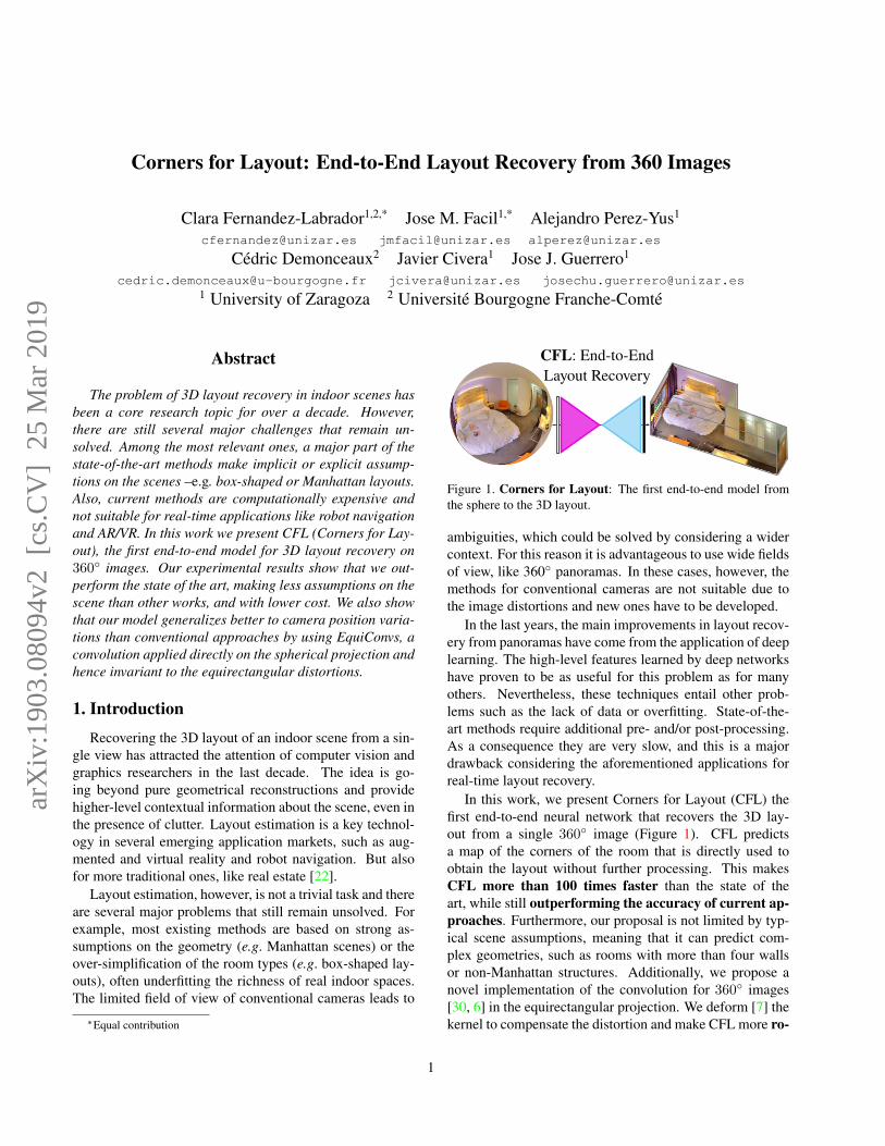
CFL: End-to-EndLayout Recovery
Figure 1. Corners for Layout: The first end-to-end model fromthe sphere to the 3D layout.
ambiguities, which could be solved by considering a widercontext. For this reason it is advantageous to use wide fieldsof view, like 360◦ panoramas. In these cases, however, themethods for conventional cameras are not suitable due tothe image distortions and new ones have to be developed.
In the last years, the main improvements in layout recov-ery from panoramas have come from the application of deeplearning. The high-level features learned by deep networkshave proven to be as useful for this problem as for manyothers. Nevertheless, these techniques entail other prob-lems such as the lack of data or overfitting. State-of-the-art methods require additional pre- and/or post-processing.As a consequence they are very slow, and this is a majordrawback considering the aforementioned applications forreal-time layout recovery.
In this work, we present Corners for Layout (CFL) thefirst end-to-end neural network that recovers the 3D lay-out from a single 360◦ image (Figure 1). CFL predictsa map of the corners of the room that is directly used toobtain the layout without further processing. This makesCFL more than 100 times faster than the state of theart, while still outperforming the accuracy of current ap-proaches. Furthermore, our proposal is not limited by typ-ical scene assumptions, meaning that it can predict com-plex geometries, such as rooms with more than four wallsor non-Manhattan structures. Additionally, we propose anovel implementation of the convolution for 360◦ images[30, 6] in the equirectangular projection. We deform [7] thekernel to compensate the distortion and make CFL more ro-
1
arX
iv:1
903.
0809
4v2
[cs
.CV
] 2
5 M
ar 2
019
bust to camera rotation and pose variations. Hence, it isequivalent to applying directly a convolution operation tothe spherical image, which is geometrically more coherentthan applying a standard convolution on the equirectangu-lar panorama. We have extensively evaluated our network intwo public datasets with several training configurations, in-cluding data augmentation techniques to address occlusionsby enforcing the network to learn from the context. Ourcode and labeled dataset can be found here: CFL webpage.
2. Related WorkThe layout of a room provides a strong prior for other
visual tasks like depth recovery [11], realistic insertions ofvirtual objects into indoor images [18], indoor object recog-nition [3, 29] or human pose estimation [15]. A large vari-ety of methods have been developed for this purpose usingmultiple input images [31, 14] or depth sensors [35], whichdeliver high-quality reconstruction results. For the commoncase when a single RGB image is available, the problem be-comes considerably more challenging and researchers needvery often to rely on strong assumptions.
The seminal approaches to layout prediction from a sin-gle view were [9, 21], followed by [17, 27]. They basicallymodel the layout of the room with a vanishing-point-aligned3D box, being hence constrained to this particular roomgeometry and unable to generalize to others appearing fre-quently in real applications. Most recent approaches exploitCNNs and their excellent performance in a wide range ofapplications such as image classification, segmentation anddetection. [23, 24, 36, 38], for example, focus on predict-ing the informative edges separating the geometric classes(walls, floor and ceiling). Alternatively, Dasgupta et al. [8]proposed a FCN to predict labels for each of the surfacesof the room. All these methods require extra computationadded to the forward propagation of the network to retrievethe actual layout. In [20], for example, an end-to-end net-work predicts the layout corners in a perspective image, butafter that it has to infer the room type within a limited set ofmanually chosen configurations.
While layout recovery from conventional images hasprogressed rapidly with both geometry and deep learning,the works that address these challenges using omnidirec-tional images are still very few. Panoramic cameras havethe potential to improve the performance of the task: their360◦ field of view captures the entire viewing sphere sur-rounding its optical center, allowing to acquire the wholeroom at once and hence predicting layouts with more vi-sual information. PanoContext [37] was the first work thatextended the frameworks designed for perspective imagesto panoramas. It recovers both the layout, which is alsoassumed as a simple 3D box, and bounding boxes for themost salient objects inside the room. Pano2CAD [33] ex-tends the method to non-cuboid rooms, but it is limited by
its dependence on the output of object detectors. Motivatedby the need of addressing complex room geometries, [13]generates layout hypotheses by geometric reasoning from asmall set of structural corners obtained from the combina-tion of geometry and deep learning. The most recent worksalong this line are LayoutNet [39], that trains a FCN frompanoramas and vanishing lines, generating the layout mod-els from edge and corner maps, and DuLa-Net [34], thatpredicts Manhattan-world layouts leveraging a perspectiveceiling-view of the room. All of these approaches requirepre- or post-processing steps like line and vanishing pointextraction or room model fitting, that increase their cost.
In addition to all the challenges mentioned above,we also notice that there is an incrongruence betweenpanoramic images and conventional CNNs. The space-varying distortions caused by the equirectangular represen-tation makes the translational weight sharing ineffective.Very recently, Cohen et al. [6] did a relevant theoreticalcontribution by studying convolutions on the sphere us-ing spectral analysis. However, it is not clearly demon-strated whether Spherical CNNs can reach the same ac-curacy and efficiency on equirectangular images. OurEquiConvs have more in common with the idea of [30], thatproposes distortion-aware convolutional filters to train theirmodel using conventional perspective images and then useit to regress depth from panoramic images. We proposea novel parameterization and implementation of the de-formable convolutions [7] by following the idea of adaptingthe receptive field of the convolutional kernels by deformingtheir shape according to the distortion of the equirectangu-lar projection.
3. Corners for LayoutHere we describe our end-to-end approach for recover-
ing the layout, i.e. the main structure of the room, fromsingle 360◦ images. After introducing some details aboutthe target data, we describe the proposed network architec-ture and how we directly transform the output into the 3Dlayout. The network architecture is adapted for StandardConvolutions and for our proposed Equirectangular Convo-lutions implementation, the latest being explained in Sec-tion 4.
3.1. Ground truth
The ground truth (GT) for every panorama consists oftwo maps, m, one represents the room edges (m = e),i.e. intersections between walls, ceiling and floor, and theother encodes the corner locations (m = c). Both mapsare defined as Ym = {ym1 , . . . , ymi , . . .}, with pixel valuesymi ∈ {0, 1}. ymi has a value of 1 if it belongs to an edgeor a corner, and 0 otherwise. We do line thickening andGaussian blur for easier convergence during training sinceit makes the loss progression continuous instead of binary.
2
3
Skip-connections
Preliminarypredictions
ResNet-50
46
3
3
256x128Input Panorama
Skip-connections
Preliminarypredictions
ResNet-50
46
3
Standard Convolution
Equirectangular Convolution
Upconvolution
Pooling
Equirectangular Convolution + Unpooling
128x64Output Corner/Edge Maps
CFL StdConvs.
CFL EquiConvs.
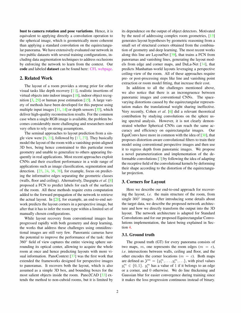
Figure 2. CFL architecture. Our network is built upon ResNet-50, adding a single decoder that jointly predicts edge and cornermaps. Here we propose two network variations: on top, the net-work applies StdConvs on the equirectangular panorama, whereasthe one on the bottom applies EquiConvs directly on the sphere.
The loss is gradually reduced as the prediction approachesthe target.
Notice here that our target is considerably simpler thanothers that usually divide the ground truth into differentclasses. This contributes to the small computational foot-print of our proposal. For example, [23, 38] use indepen-dent feature maps for background, wall-floor, wall-wall andwall-ceiling edges. A full image segmentation into left,front and right wall, ceiling and floor categories is per-formed in [8]. In [20], they represent a total of 48 differentcorner types by a 2D Gaussian heatmap centered at the truekeypoint location. Here, instead, we only use two probabil-ity maps, one for edges and another one for corners – seeoutputs in the Figure 2.
3.2. Network architecture
The proposed FCN follows the encoder-decoder struc-ture and builds upon ResNet-50 [16]. We replace the finalfully-connected layer with a decoder that jointly predictslayout edges and corners locations already refined. We il-lustrate the proposed architecture in Figure 2.
Encoder. Most of deep-learning approaches facing lay-out recovery problem have made use of the VGG16 [28] asencoder [23, 8, 20]. Instead, [38] builds their model overResNet-101 [16] outperforming the state of the art. Here,we use ResNet-50 [16], pre-trained on the ImageNet dataset[26], which leads to a faster convergence due to the gen-eral low-level features learned from ImageNet. Residual
1
1'
2 3
2' 3'
4
4' 4
4'1
1'
2
2'
2
2'
3
3'
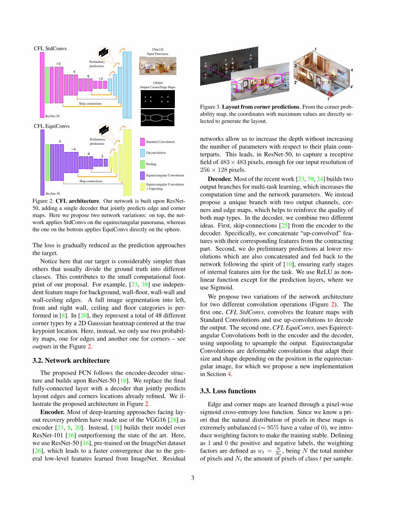
Figure 3. Layout from corner predictions. From the corner prob-ability map, the coordinates with maximum values are directly se-lected to generate the layout.
networks allow us to increase the depth without increasingthe number of parameters with respect to their plain coun-terparts. This leads, in ResNet-50, to capture a receptivefield of 483×483 pixels, enough for our input resolution of256× 128 pixels.
Decoder. Most of the recent work [23, 39, 24] builds twooutput branches for multi-task learning, which increases thecomputation time and the network parameters. We insteadpropose a unique branch with two output channels, cor-ners and edge maps, which helps to reinforce the quality ofboth map types. In the decoder, we combine two differentideas. First, skip-connections [25] from the encoder to thedecoder. Specifically, we concatenate “up-convolved” fea-tures with their corresponding features from the contractingpart. Second, we do preliminary predictions at lower res-olutions which are also concatenated and fed back to thenetwork following the spirit of [10], ensuring early stagesof internal features aim for the task. We use ReLU as non-linear function except for the prediction layers, where weuse Sigmoid.
We propose two variations of the network architecturefor two different convolution operations (Figure 2). Thefirst one, CFL StdConvs, convolves the feature maps withStandard Convolutions and use up-convolutions to decodethe output. The second one, CFL EquiConvs, uses Equirect-angular Convolutions both in the encoder and the decoder,using unpooling to upsample the output. EquirectangularConvolutions are deformable convolutions that adapt theirsize and shape depending on the position in the equirectan-gular image, for which we propose a new implementationin Section 4.
3.3. Loss functions
Edge and corner maps are learned through a pixel-wisesigmoid cross-entropy loss function. Since we know a pri-ori that the natural distribution of pixels in these maps isextremely unbalanced (∼ 95% have a value of 0), we intro-duce weighting factors to make the training stable. Definingas 1 and 0 the positive and negative labels, the weightingfactors are defined as wt = N
Nt, being N the total number
of pixels and Nt the amount of pixels of class t per sample.
3
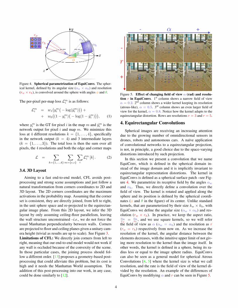
Figure 4. Spherical parametrization of EquiConvs. The spher-ical kernel, defined by its angular size (αw × αh) and resolution(rw × rh), is convolved around the sphere with angles φ and θ.
The per-pixel per-map loss Lmi is as follows:
Lmi = w1
(ymi(− log(ymi )
))+
+ w0
((1− ymi )
(− log(1− ymi )
)), (1)
where ymi is the GT for pixel i in the map m and ymi is thenetwork output for pixel i and map m. We minimize thisloss at 4 different resolutions k = {1, . . . , 4}, specificallyin the network output (k = 4) and 3 intermediate layers(k = {1, . . . , 3}). The total loss is then the sum over allpixels, the 4 resolutions and both the edge and corner maps
L =∑
k={1,...,4}
∑m={e,c}
∑i
Lmi [k] . (2)
3.4. 3D Layout
Aiming to a fast end-to-end model, CFL avoids post-processing and strong scene assumptions and just follow anatural transformation from corners coordinates to 2D and3D layout. The 2D corners coordinates are the maximumactivations in the probability map. Assuming that the cornerset is consistent, they are directly joined, from left to right,in the unit sphere space and re-projected to the equirectan-gular image plane. From this 2D layout, we infer the 3Dlayout by only assuming ceiling-floor parallelism, leavingthe wall structure unconstrained –i.e., we do not force theusual Manhattan perpendicularity between walls. Cornersare projected to floor and ceiling planes given a unitary cam-era height (trivial as results are up to scale). See Figure 3.Limitations of CFL: We directly join corners from left toright, meaning that our end-to-end model would not work ifany wall is occluded because of the convexity of the scene.In those particular cases, the joining process should fol-low a different order. [13] proposes a geometry-based post-processing that could alleviate this problem, but its cost ishigh and it needs the Manhattan World assumption. Theaddition of this post-processing into our work, in any case,could be done similarly to [12].
+
-
- +
Figure 5. Effect of changing field of view α (rad) and resolu-tion r in EquiConvs. 1st column shows a narrow field of viewα = 0.2. 2nd column shows a wider kernel keeping its resolution(atrous-like), α = 0.5. 3rd column shows an even larger field ofview for the kernel, α = 0.8. Notice how the kernel adapts to theequirectangular distortion. Rows are resolutions r = 3 and r = 5.
4. Equirectangular Convolutions
Spherical images are receiving an increasing attentiondue to the growing number of omnidirectional sensors indrones, robots and autonomous cars. A naıve applicationof convolutional networks to a equirectangular projection,is not, in principle, a good choice due to the space-varyingdistortions introduced by such projection.
In this section we present a convolution that we nameEquiConv, which is defined in the spherical domain in-stead of the image domain and it is implicitly invariant toequirectangular representation distortions. The kernel inEquiConvs is defined as a spherical surface patch –see Fig-ure 4. We parametrize its receptive field by the angles αwand αh. Thus, we directly define a convolution over thefield of view. The kernel is rotated and applied along thesphere and its position is defined by the spherical coordi-nates (φ and θ in the figure) of its center. Unlike standardkernels, that are parameterized by their size kw × kh, withEquiConvs we define the angular size (αw × αh) and res-olution (rw × rh). In practice, we keep the aspect ratio,αw
rw= αh
rh, and we use square kernels, so we will refer
the field of view as α (αw = αh) and the resolution as r(rw = rh) respectively from now on. As we increase theresolution of the kernel, the angular distance between theelements decreases, with the intuitive upper limit of not giv-ing more resolution to the kernel than the image itself. Inother words, the kernel is defined in a sphere, being its ra-dius less or equal to the image sphere radius. EquiConvscan also be seen as a general model for spherical AtrousConvolutions [4, 5] where the kernel size is what we callresolution, and the rate is the field of view of the kernel di-vided by the resolution. An example of the differences ofEquiConvs by modifiying α and r can be seen in Figure 5.
4
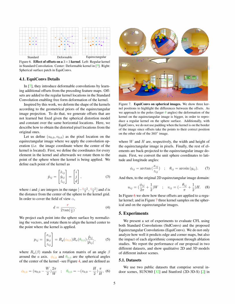
Standard Deformable EquirectangularFigure 6. Effect of offsets on a 3×3 kernel. Left: Regular kernelin Standard Convolution. Center: Deformable kernel in [7]. Right:Spherical surface patch in EquiConvs.
4.1. EquiConvs Details
In [7], they introduce deformable convolutions by learn-ing additional offsets from the preceding feature maps. Off-sets are added to the regular kernel locations in the StandardConvolution enabling free form deformation of the kernel.
Inspired by this work, we deform the shape of the kernelsaccording to the geometrical priors of the equirectangularimage projection. To do that, we generate offsets that arenot learned but fixed given the spherical distortion modeland constant over the same horizontal locations. Here, wedescribe how to obtain the distorted pixel locations from theoriginal ones.
Let us define (u0,0, v0,0) as the pixel location on theequirectangular image where we apply the convolution op-eration (i.e. the image coordinate where the center of thekernel is located). First, we define the coordinates for everyelement in the kernel and afterwards we rotate them to thepoint of the sphere where the kernel is being applied. Wedefine each point of the kernel as
pij =
xijyijzij
=
ijd
, (3)
where i and j are integers in the range [− r−12 , r−12 ] and d isthe distance from the center of the sphere to the kernel grid.In order to cover the field of view α,
d =r
2 tan(α2 ). (4)
We project each point into the sphere surface by normaliz-ing the vectors, and rotate them to align the kernel center tothe point where the kernel is applied.
pij =
xijyijzij
= Ry(φ0,0)Rx(θ0,0)pij|pij |
, (5)
where Ra(β) stands for a rotation matrix of an angle βaround the a axis. φ0,0 and θ0,0 are the spherical anglesof the center of the kernel –see Figure 4, and are defined as
φ0,0 = (u0,0 −W
2)2π
W; θ0,0 = −(v0,0 −
H
2)π
H, (6)
Figure 7. EquiConvs on spherical images. We show three ker-nel positions to highlight the differences between the offsets. Aswe approach to the poles (larger θ angles) the deformation of thekernel on the equirectangular image is bigger, in order to repro-duce a regular kernel on the sphere surface. Additionally, withEquiConvs, we do not use padding when the kernel is on the borderof the image since offsets take the points to their correct positionon the other side of the 360◦ image.
where W and H are, respectively, the width and height ofthe equirectangular image in pixels. Finally, the rest of el-ements are back-projected to the equirectangular image do-main. First, we convert the unit sphere coordinates to lati-tude and longitude angles:
φij = arctan (xijzij
) ; θij = arcsin (yij). (7)
And then, to the original 2D equirectangular image domain:
uij = (φij2π
+1
2)W ; vij = (−θij
π+
1
2)H. (8)
In Figure 6 we show how these offsets are applied to a regu-lar kernel; and in Figure 7 three kernel samples on the spher-ical and on the equirectangular images.
5. ExperimentsWe present a set of experiments to evaluate CFL using
both Standard Convolutions (StdConvs) and the proposedEquirectangular Convolutions (EquiConvs). We do not onlyanalyze how well it predicts edge and corner maps, but alsothe impact of each algorithmic component through ablationstudies. We report the performance of our proposal in twodifferent datasets, and show qualitative 2D and 3D modelsof different indoor scenes.
5.1. Datasets
We use two public datasets that comprise several in-door scenes, SUN360 [32] and Stanford (2D-3D-S) [2] in
5
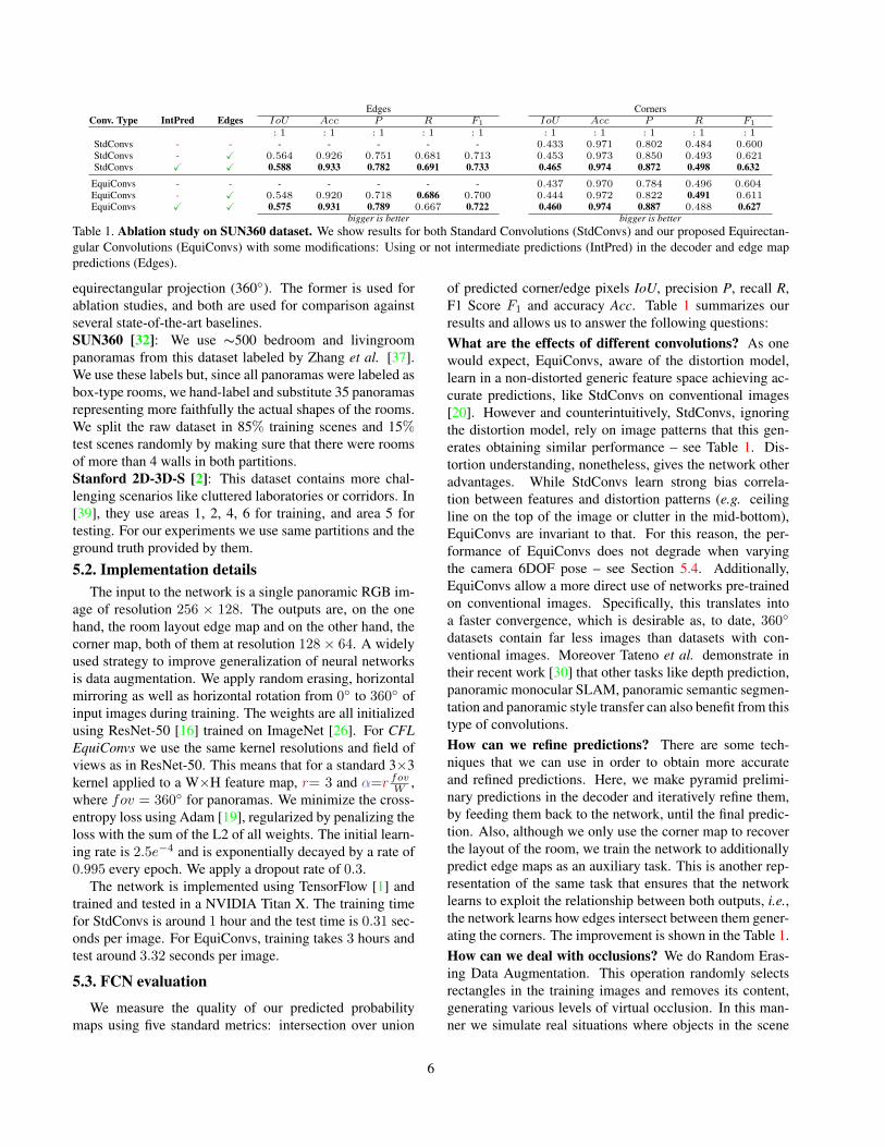
Edges CornersConv. Type IntPred Edges IoU Acc P R F1 IoU Acc P R F1
: 1 : 1 : 1 : 1 : 1 : 1 : 1 : 1 : 1 : 1StdConvs - - - - - - - 0.433 0.971 0.802 0.484 0.600StdConvs - X 0.564 0.926 0.751 0.681 0.713 0.453 0.973 0.850 0.493 0.621StdConvs X X 0.588 0.933 0.782 0.691 0.733 0.465 0.974 0.872 0.498 0.632
EquiConvs - - - - - - - 0.437 0.970 0.784 0.496 0.604EquiConvs - X 0.548 0.920 0.718 0.686 0.700 0.444 0.972 0.822 0.491 0.611EquiConvs X X 0.575 0.931 0.789 0.667 0.722 0.460 0.974 0.887 0.488 0.627
bigger is better bigger is betterTable 1. Ablation study on SUN360 dataset. We show results for both Standard Convolutions (StdConvs) and our proposed Equirectan-gular Convolutions (EquiConvs) with some modifications: Using or not intermediate predictions (IntPred) in the decoder and edge mappredictions (Edges).
equirectangular projection (360◦). The former is used forablation studies, and both are used for comparison againstseveral state-of-the-art baselines.SUN360 [32]: We use ∼500 bedroom and livingroompanoramas from this dataset labeled by Zhang et al. [37].We use these labels but, since all panoramas were labeled asbox-type rooms, we hand-label and substitute 35 panoramasrepresenting more faithfully the actual shapes of the rooms.We split the raw dataset in 85% training scenes and 15%test scenes randomly by making sure that there were roomsof more than 4 walls in both partitions.Stanford 2D-3D-S [2]: This dataset contains more chal-lenging scenarios like cluttered laboratories or corridors. In[39], they use areas 1, 2, 4, 6 for training, and area 5 fortesting. For our experiments we use same partitions and theground truth provided by them.
5.2. Implementation detailsThe input to the network is a single panoramic RGB im-
age of resolution 256 × 128. The outputs are, on the onehand, the room layout edge map and on the other hand, thecorner map, both of them at resolution 128× 64. A widelyused strategy to improve generalization of neural networksis data augmentation. We apply random erasing, horizontalmirroring as well as horizontal rotation from 0◦ to 360◦ ofinput images during training. The weights are all initializedusing ResNet-50 [16] trained on ImageNet [26]. For CFLEquiConvs we use the same kernel resolutions and field ofviews as in ResNet-50. This means that for a standard 3×3kernel applied to a W×H feature map, r= 3 and α=r fovW ,where fov = 360◦ for panoramas. We minimize the cross-entropy loss using Adam [19], regularized by penalizing theloss with the sum of the L2 of all weights. The initial learn-ing rate is 2.5e−4 and is exponentially decayed by a rate of0.995 every epoch. We apply a dropout rate of 0.3.
The network is implemented using TensorFlow [1] andtrained and tested in a NVIDIA Titan X. The training timefor StdConvs is around 1 hour and the test time is 0.31 sec-onds per image. For EquiConvs, training takes 3 hours andtest around 3.32 seconds per image.
5.3. FCN evaluation
We measure the quality of our predicted probabilitymaps using five standard metrics: intersection over union
of predicted corner/edge pixels IoU, precision P, recall R,F1 Score F1 and accuracy Acc. Table 1 summarizes ourresults and allows us to answer the following questions:What are the effects of different convolutions? As onewould expect, EquiConvs, aware of the distortion model,learn in a non-distorted generic feature space achieving ac-curate predictions, like StdConvs on conventional images[20]. However and counterintuitively, StdConvs, ignoringthe distortion model, rely on image patterns that this gen-erates obtaining similar performance – see Table 1. Dis-tortion understanding, nonetheless, gives the network otheradvantages. While StdConvs learn strong bias correla-tion between features and distortion patterns (e.g. ceilingline on the top of the image or clutter in the mid-bottom),EquiConvs are invariant to that. For this reason, the per-formance of EquiConvs does not degrade when varyingthe camera 6DOF pose – see Section 5.4. Additionally,EquiConvs allow a more direct use of networks pre-trainedon conventional images. Specifically, this translates intoa faster convergence, which is desirable as, to date, 360◦
datasets contain far less images than datasets with con-ventional images. Moreover Tateno et al. demonstrate intheir recent work [30] that other tasks like depth prediction,panoramic monocular SLAM, panoramic semantic segmen-tation and panoramic style transfer can also benefit from thistype of convolutions.How can we refine predictions? There are some tech-niques that we can use in order to obtain more accurateand refined predictions. Here, we make pyramid prelimi-nary predictions in the decoder and iteratively refine them,by feeding them back to the network, until the final predic-tion. Also, although we only use the corner map to recoverthe layout of the room, we train the network to additionallypredict edge maps as an auxiliary task. This is another rep-resentation of the same task that ensures that the networklearns to exploit the relationship between both outputs, i.e.,the network learns how edges intersect between them gener-ating the corners. The improvement is shown in the Table 1.How can we deal with occlusions? We do Random Eras-ing Data Augmentation. This operation randomly selectsrectangles in the training images and removes its content,generating various levels of virtual occlusion. In this man-ner we simulate real situations where objects in the scene
6
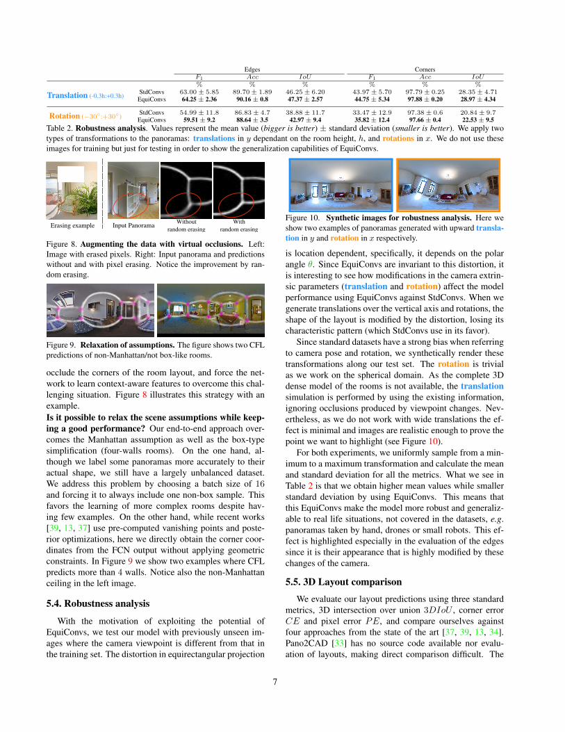
Edges CornersF1 Acc IoU F1 Acc IoU% % % % % %
Translation (-0.3h:+0.3h)StdConvs 63.00± 5.85 89.70± 1.89 46.25± 6.20 43.97± 5.70 97.79± 0.25 28.35± 4.71
EquiConvs 64.25± 2.36 90.16± 0.8 47.37± 2.57 44.75± 5.34 97.88± 0.20 28.97± 4.34
Rotation (−30◦:+30◦)StdConvs 54.99± 11.8 86.83± 4.7 38.88± 11.7 33.47± 12.9 97.38± 0.6 20.84± 9.7
EquiConvs 59.51± 9.2 88.64± 3.5 42.97± 9.4 35.82± 12.4 97.66± 0.4 22.53± 9.5Table 2. Robustness analysis. Values represent the mean value (bigger is better) ± standard deviation (smaller is better). We apply twotypes of transformations to the panoramas: translations in y dependant on the room height, h, and rotations in x. We do not use theseimages for training but just for testing in order to show the generalization capabilities of EquiConvs.
Input Panorama Without random erasing
Withrandom erasingErasing example
Figure 8. Augmenting the data with virtual occlusions. Left:Image with erased pixels. Right: Input panorama and predictionswithout and with pixel erasing. Notice the improvement by ran-dom erasing.
Figure 9. Relaxation of assumptions. The figure shows two CFLpredictions of non-Manhattan/not box-like rooms.
occlude the corners of the room layout, and force the net-work to learn context-aware features to overcome this chal-lenging situation. Figure 8 illustrates this strategy with anexample.Is it possible to relax the scene assumptions while keep-ing a good performance? Our end-to-end approach over-comes the Manhattan assumption as well as the box-typesimplification (four-walls rooms). On the one hand, al-though we label some panoramas more accurately to theiractual shape, we still have a largely unbalanced dataset.We address this problem by choosing a batch size of 16and forcing it to always include one non-box sample. Thisfavors the learning of more complex rooms despite hav-ing few examples. On the other hand, while recent works[39, 13, 37] use pre-computed vanishing points and poste-rior optimizations, here we directly obtain the corner coor-dinates from the FCN output without applying geometricconstraints. In Figure 9 we show two examples where CFLpredicts more than 4 walls. Notice also the non-Manhattanceiling in the left image.
5.4. Robustness analysis
With the motivation of exploiting the potential ofEquiConvs, we test our model with previously unseen im-ages where the camera viewpoint is different from that inthe training set. The distortion in equirectangular projection
Figure 10. Synthetic images for robustness analysis. Here weshow two examples of panoramas generated with upward transla-tion in y and rotation in x respectively.
is location dependent, specifically, it depends on the polarangle θ. Since EquiConvs are invariant to this distortion, itis interesting to see how modifications in the camera extrin-sic parameters (translation and rotation) affect the modelperformance using EquiConvs against StdConvs. When wegenerate translations over the vertical axis and rotations, theshape of the layout is modified by the distortion, losing itscharacteristic pattern (which StdConvs use in its favor).
Since standard datasets have a strong bias when referringto camera pose and rotation, we synthetically render thesetransformations along our test set. The rotation is trivialas we work on the spherical domain. As the complete 3Ddense model of the rooms is not available, the translationsimulation is performed by using the existing information,ignoring occlusions produced by viewpoint changes. Nev-ertheless, as we do not work with wide translations the ef-fect is minimal and images are realistic enough to prove thepoint we want to highlight (see Figure 10).
For both experiments, we uniformly sample from a min-imum to a maximum transformation and calculate the meanand standard deviation for all the metrics. What we see inTable 2 is that we obtain higher mean values while smallerstandard deviation by using EquiConvs. This means thatthis EquiConvs make the model more robust and generaliz-able to real life situations, not covered in the datasets, e.g.panoramas taken by hand, drones or small robots. This ef-fect is highlighted especially in the evaluation of the edgessince it is their appearance that is highly modified by thesechanges of the camera.
5.5. 3D Layout comparison
We evaluate our layout predictions using three standardmetrics, 3D intersection over union 3DIoU , corner errorCE and pixel error PE, and compare ourselves againstfour approaches from the state of the art [37, 39, 13, 34].Pano2CAD [33] has no source code available nor evalu-ation of layouts, making direct comparison difficult. The
7
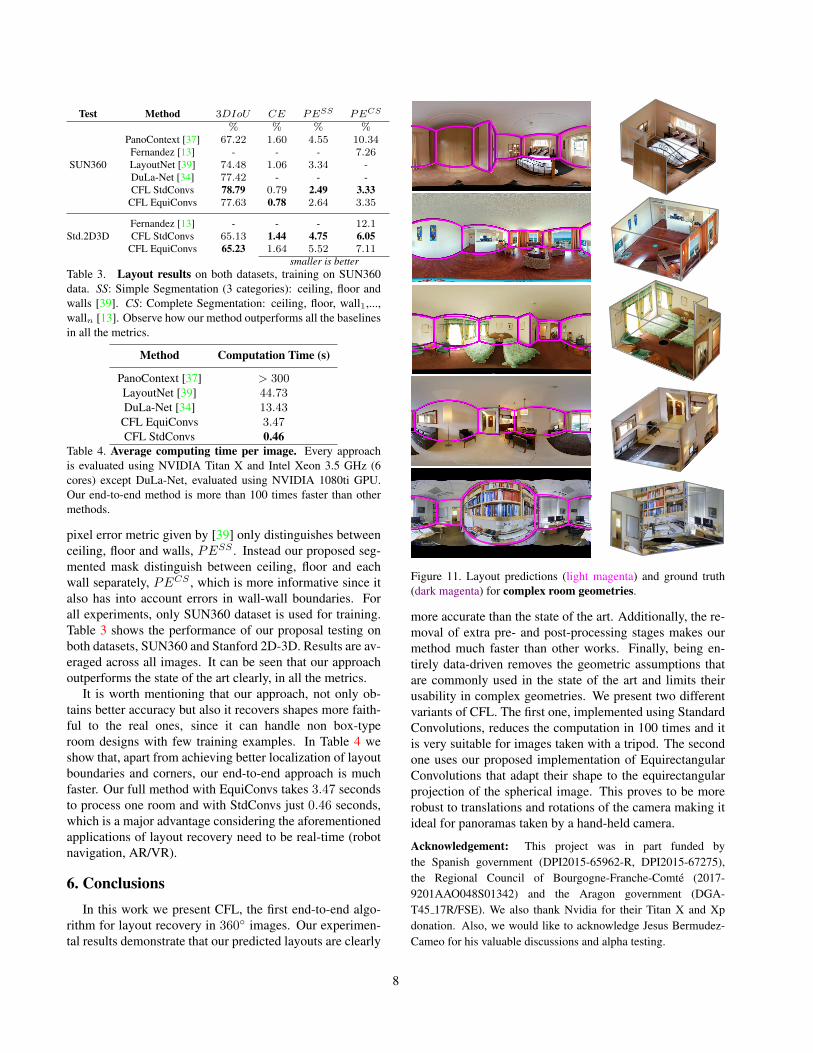
Test Method 3DIoU CE PESS PECS
% % % %
SUN360
PanoContext [37] 67.22 1.60 4.55 10.34Fernandez [13] - - - 7.26LayoutNet [39] 74.48 1.06 3.34 -DuLa-Net [34] 77.42 - - -CFL StdConvs 78.79 0.79 2.49 3.33
CFL EquiConvs 77.63 0.78 2.64 3.35
Std.2D3DFernandez [13] - - - 12.1CFL StdConvs 65.13 1.44 4.75 6.05
CFL EquiConvs 65.23 1.64 5.52 7.11smaller is better
Table 3. Layout results on both datasets, training on SUN360data. SS: Simple Segmentation (3 categories): ceiling, floor andwalls [39]. CS: Complete Segmentation: ceiling, floor, wall1,...,walln [13]. Observe how our method outperforms all the baselinesin all the metrics.
Method Computation Time (s)
PanoContext [37] > 300LayoutNet [39] 44.73DuLa-Net [34] 13.43
CFL EquiConvs 3.47CFL StdConvs 0.46
Table 4. Average computing time per image. Every approachis evaluated using NVIDIA Titan X and Intel Xeon 3.5 GHz (6cores) except DuLa-Net, evaluated using NVIDIA 1080ti GPU.Our end-to-end method is more than 100 times faster than othermethods.
pixel error metric given by [39] only distinguishes betweenceiling, floor and walls, PESS . Instead our proposed seg-mented mask distinguish between ceiling, floor and eachwall separately, PECS , which is more informative since italso has into account errors in wall-wall boundaries. Forall experiments, only SUN360 dataset is used for training.Table 3 shows the performance of our proposal testing onboth datasets, SUN360 and Stanford 2D-3D. Results are av-eraged across all images. It can be seen that our approachoutperforms the state of the art clearly, in all the metrics.
It is worth mentioning that our approach, not only ob-tains better accuracy but also it recovers shapes more faith-ful to the real ones, since it can handle non box-typeroom designs with few training examples. In Table 4 weshow that, apart from achieving better localization of layoutboundaries and corners, our end-to-end approach is muchfaster. Our full method with EquiConvs takes 3.47 secondsto process one room and with StdConvs just 0.46 seconds,which is a major advantage considering the aforementionedapplications of layout recovery need to be real-time (robotnavigation, AR/VR).
6. ConclusionsIn this work we present CFL, the first end-to-end algo-
rithm for layout recovery in 360◦ images. Our experimen-tal results demonstrate that our predicted layouts are clearly
Figure 11. Layout predictions (light magenta) and ground truth(dark magenta) for complex room geometries.
more accurate than the state of the art. Additionally, the re-moval of extra pre- and post-processing stages makes ourmethod much faster than other works. Finally, being en-tirely data-driven removes the geometric assumptions thatare commonly used in the state of the art and limits theirusability in complex geometries. We present two differentvariants of CFL. The first one, implemented using StandardConvolutions, reduces the computation in 100 times and itis very suitable for images taken with a tripod. The secondone uses our proposed implementation of EquirectangularConvolutions that adapt their shape to the equirectangularprojection of the spherical image. This proves to be morerobust to translations and rotations of the camera making itideal for panoramas taken by a hand-held camera.
Acknowledgement: This project was in part funded bythe Spanish government (DPI2015-65962-R, DPI2015-67275),the Regional Council of Bourgogne-Franche-Comte (2017-9201AAO048S01342) and the Aragon government (DGA-T45 17R/FSE). We also thank Nvidia for their Titan X and Xpdonation. Also, we would like to acknowledge Jesus Bermudez-Cameo for his valuable discussions and alpha testing.
8
References[1] M. Abadi, P. Barham, J. Chen, Z. Chen, A. Davis, J. Dean,
M. Devin, S. Ghemawat, G. Irving, M. Isard, et al. Tensor-flow: A system for large-scale machine learning. In OSDI,volume 16, pages 265–283, 2016. 6
[2] I. Armeni, A. Sax, A. R. Zamir, and S. Savarese. Joint 2D-3D-Semantic Data for Indoor Scene Understanding. ArXiv,Feb. 2017. 5, 6
[3] S. Y. Bao, M. Sun, and S. Savarese. Toward coherent objectdetection and scene layout understanding. Image and VisionComputing, 29(9):569–579, 2011. 2
[4] L.-C. Chen, G. Papandreou, I. Kokkinos, K. Murphy, andA. L. Yuille. Deeplab: Semantic image segmentation withdeep convolutional nets, atrous convolution, and fully con-nected crfs. IEEE transactions on pattern analysis and ma-chine intelligence, 40(4):834–848, 2018. 4
[5] L.-C. Chen, G. Papandreou, F. Schroff, and H. Adam. Re-thinking atrous convolution for semantic image segmenta-tion. arXiv preprint arXiv:1706.05587, 2017. 4
[6] T. S. Cohen, M. Geiger, J. Kohler, and M. Welling. Sphericalcnns. arXiv preprint arXiv:1801.10130, 2018. 1, 2
[7] J. Dai, H. Qi, Y. Xiong, Y. Li, G. Zhang, H. Hu, andY. Wei. Deformable convolutional networks. CoRR,abs/1703.06211, 1(2):3, 2017. 1, 2, 5
[8] S. Dasgupta, K. Fang, K. Chen, and S. Savarese. Delay: Ro-bust spatial layout estimation for cluttered indoor scenes. InIEEE Conference on Computer Vision and Pattern Recogni-tion, pages 616–624, 2016. 2, 3
[9] E. Delage, H. Lee, and A. Y. Ng. A dynamic bayesian net-work model for autonomous 3D reconstruction from a sin-gle indoor image. In IEEE Computer Society Conference onComputer Vision and Pattern Recognition, volume 2, pages2418–2428, 2006. 2
[10] A. Dosovitskiy, P. Fischer, E. Ilg, P. Hausser, C. Hazirbas,V. Golkov, P. van der Smagt, D. Cremers, and T. Brox.Flownet: Learning optical flow with convolutional networks.In Proceedings of the IEEE International Conference onComputer Vision, pages 2758–2766, 2015. 3
[11] D. Eigen and R. Fergus. Predicting depth, surface normalsand semantic labels with a common multi-scale convolu-tional architecture. In IEEE International Conference onComputer Vision, pages 2650–2658, 2015. 2
[12] C. Fernandez-Labrador, J. M. Facil, A. Perez-Yus, C. De-monceaux, and J. J. Guerrero. Panoroom: From the sphereto the 3d layout. arXiv preprint arXiv:1808.09879, 2018. 4
[13] C. Fernandez-Labrador, A. Perez-Yus, G. Lopez-Nicolas,and J. J. Guerrero. Layouts from panoramic images withgeometry and deep learning. IEEE Robotics and AutomationLetters, 3(4):3153–3160, 2018. 2, 4, 7, 8
[14] A. Flint, D. Murray, and I. Reid. Manhattan scene under-standing using monocular, stereo, and 3d features. In Com-puter Vision (ICCV), 2011 IEEE International Conferenceon, pages 2228–2235. IEEE, 2011. 2
[15] D. F. Fouhey, V. Delaitre, A. Gupta, A. A. Efros, I. Laptev,and J. Sivic. People watching: Human actions as a cue forsingle view geometry. International journal of computer vi-sion, 110(3):259–274, 2014. 2
[16] K. He, X. Zhang, S. Ren, and J. Sun. Deep residual learningfor image recognition. In Proceedings IEEE Conference onComputer Vision and Pattern Recognition, pages 770–778,2016. 3, 6
[17] V. Hedau, D. Hoiem, and D. Forsyth. Recovering the spatiallayout of cluttered rooms. In IEEE International Conferenceon Computer Vision, pages 1849–1856, 2009. 2
[18] K. Karsch, V. Hedau, D. Forsyth, and D. Hoiem. Renderingsynthetic objects into legacy photographs. ACM Transac-tions on Graphics (TOG), 30(6):157, 2011. 2
[19] D. P. Kingma and J. Ba. Adam: A method for stochasticoptimization. arXiv preprint arXiv:1412.6980, 2014. 6
[20] C. Lee, V. Badrinarayanan, T. Malisiewicz, and A. Rabi-novich. RoomNet: End-to-end room layout estimation. InIEEE International Conference on Computer Vision, 2017.2, 3, 6
[21] D. C. Lee, M. Hebert, and T. Kanade. Geometric reason-ing for single image structure recovery. In IEEE Conferenceon Computer Vision and Pattern Recognition (CVPR), pages2136–2143, 2009. 2
[22] C. Liu, A. G. Schwing, K. Kundu, R. Urtasun, and S. Fidler.Rent3d: Floor-plan priors for monocular layout estimation.In The IEEE Conference on Computer Vision and PatternRecognition (CVPR), June 2015. 1
[23] A. Mallya and S. Lazebnik. Learning informative edge mapsfor indoor scene layout prediction. In IEEE InternationalConference on Computer Vision, pages 936–944, 2015. 2, 3
[24] Y. Ren, S. Li, C. Chen, and C.-C. J. Kuo. A coarse-to-fineindoor layout estimation (cfile) method. In Asian Conferenceon Computer Vision, pages 36–51, 2016. 2, 3
[25] O. Ronneberger, P. Fischer, and T. Brox. U-net: Convolu-tional networks for biomedical image segmentation. In MIC-CAI, pages 234–241, 2015. 3
[26] O. Russakovsky, J. Deng, H. Su, J. Krause, S. Satheesh,S. Ma, Z. Huang, A. Karpathy, A. Khosla, M. Bernstein,et al. Imagenet large scale visual recognition challenge.International Journal of Computer Vision, 115(3):211–252,2015. 3, 6
[27] A. G. Schwing, S. Fidler, M. Pollefeys, and R. Urtasun. Boxin the box: Joint 3D layout and object reasoning from sin-gle images. In IEEE International Conference on ComputerVision, pages 353–360, 2013. 2
[28] K. Simonyan and A. Zisserman. Very deep convolutionalnetworks for large-scale image recognition. arXiv preprintarXiv:1409.1556, 2014. 3
[29] S. Song and J. Xiao. Deep sliding shapes for amodal 3d ob-ject detection in rgb-d images. In Proceedings of the IEEEConference on Computer Vision and Pattern Recognition,pages 808–816, 2016. 2
[30] K. Tateno, N. Navab, and F. Tombari. Distortion-aware con-volutional filters for dense prediction in panoramic images.In Proceedings of the European Conference on Computer Vi-sion (ECCV), pages 707–722, 2018. 1, 2, 6
[31] G. Tsai, C. Xu, J. Liu, and B. Kuipers. Real-time indoorscene understanding using bayesian filtering with motioncues. In Computer Vision (ICCV), 2011 IEEE InternationalConference on, pages 121–128. IEEE, 2011. 2
9
[32] J. Xiao, K. Ehinger, A. Oliva, and A. Torralba. Recognizingscene viewpoint using panoramic place representation. InIEEE Conference on Computer Vision and Pattern Recogni-tion, pages 2695–2702, 2012. 5, 6
[33] J. Xu, B. Stenger, T. Kerola, and T. Tung. Pano2CAD: Roomlayout from a single panorama image. In IEEE Winter Con-ference on Applications of Computer Vision, pages 354–362,2017. 2, 7
[34] S.-T. Yang, F.-E. Wang, C.-H. Peng, P. Wonka, M. Sun, andH.-K. Chu. Dula-net: A dual-projection network for estimat-ing room layouts from a single rgb panorama. arXiv preprintarXiv:1811.11977, 2018. 2, 7, 8
[35] J. Zhang, C. Kan, A. G. Schwing, and R. Urtasun. Estimatingthe 3d layout of indoor scenes and its clutter from depth sen-sors. In 2013 IEEE International Conference on ComputerVision, pages 1273–1280. IEEE, 2013. 2
[36] W. Zhang, W. Zhang, K. Liu, and J. Gu. Learning to predicthigh-quality edge maps for room layout estimation. Trans-actions on Multimedia, 19(5):935–943, 2017. 2
[37] Y. Zhang, S. Song, P. Tan, and J. Xiao. PanoContext: Awhole-room 3D context model for panoramic scene under-standing. In European Conference on Computer Vision,pages 668–686. Springer, 2014. 2, 6, 7, 8
[38] H. Zhao, M. Lu, A. Yao, Y. Guo, Y. Chen, and L. Zhang.Physics inspired optimization on semantic transfer features:An alternative method for room layout estimation. arXivpreprint arXiv:1707.00383, 2017. 2, 3
[39] C. Zou, A. Colburn, Q. Shan, and D. Hoiem. Layoutnet:Reconstructing the 3d room layout from a single rgb image.In Proceedings IEEE Conference on Computer Vision andPattern Recognition, pages 2051–2059, 2018. 2, 3, 6, 7, 8
10