BEST 70P Cyclotron Factory Test
3
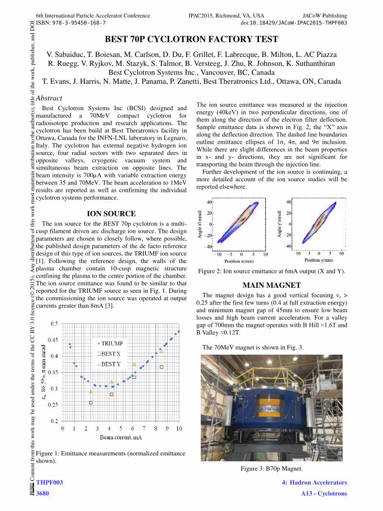
BEST 70P CYCLOTRON FACTORY TEST V. Sabaiduc, T. Boiesan, M. Carlson, D. Du, F. Grillet, F. Labrecque, B. Milton, L. AC Piazza R. Ruegg, V. Ryjkov, M. Stazyk, S. Talmor, B. Versteeg, J. Zhu, R. Johnson, K. Suthanthiran Best Cyclotron Systems Inc., Vancouver, BC, Canada T. Evans, J. Harris, N. Matte, J. Panama, P. Zanetti, Best Theratronics Ltd., Ottawa, ON, Canada Abstract Best Cyclotron Systems Inc (BCSI) designed and manufactured a 70MeV compact cyclotron for radioisotope production and research applications. The cyclotron has been build at Best Theratronics facility in Ottawa, Canada for the INFN-LNL laboratory in Legnaro, Italy. The cyclotron has external negative hydrogen ion source, four radial sectors with two separated dees in opposite valleys, cryogenic vacuum system and simultaneous beam extraction on opposite lines. The beam intensity is 700μA with variable extraction energy between 35 and 70MeV. The beam acceleration to 1MeV results are reported as well as confirming the individual cyclotron systems performance. ION SOURCE The ion source for the BEST 70p cyclotron is a multi- cusp filament driven arc discharge ion source. The design parameters are chosen to closely follow, where possible, the published design parameters of the de facto reference design of this type of ion sources, the TRIUMF ion source [1]. Following the reference design, the walls of the plasma chamber contain 10-cusp magnetic structure confining the plasma to the centre portion of the chamber. The ion source emittance was found to be similar to that reported for the TRIUMF source as seen in Fig. 1. During the commissioning the ion source was operated at output currents greater than 8mA [3]. Figure 1: Emittance measurements (normalized emittance shown). The ion source emittance was measured at the injection energy (40keV) in two perpendicular directions, one of them along the direction of the electron filter deflection. Sample emittance data is shown in Fig. 2, the “X” axis along the deflection direction. The dashed line boundaries outline emittance ellipses of 1σ, 4σ, and 9σ inclusion. While there are slight differences in the beam properties in x- and y- directions, they are not significant for transporting the beam through the injection line. Further development of the ion source is continuing, a more detailed account of the ion source studies will be reported elsewhere. Figure 2: Ion source emittance at 6mA output (X and Y). MAIN MAGNET The magnet design has a good vertical focusing ν z > 0.25 after the first few turns (0.4 at full extraction energy) and minimum magnet gap of 45mm to ensure low beam losses and high beam current acceleration. For a valley gap of 700mm the magnet operates with B Hill ≈1.6T and B Valley ≈0.12T. The 70MeV magnet is shown in Fig. 3. Figure 3: B70p Magnet. 6th International Particle Accelerator Conference IPAC2015, Richmond, VA, USA JACoW Publishing ISBN: 978-3-95450-168-7 doi:10.18429/JACoW-IPAC2015-THPF003 THPF003 3680 Content from this work may be used under the terms of the CC BY 3.0 licence (© 2015). Any distribution of this work must maintain attribution to the author(s), title of the work, publisher, and DOI. 4: Hadron Accelerators A13 - Cyclotrons
Transcript of BEST 70P Cyclotron Factory Test
BEST 70P CYCLOTRON FACTORY TEST
V. Sabaiduc, T. Boiesan, M. Carlson, D. Du, F. Grillet, F. Labrecque, B. Milton, L. AC Piazza
R. Ruegg, V. Ryjkov, M. Stazyk, S. Talmor, B. Versteeg, J. Zhu, R. Johnson, K. Suthanthiran
Best Cyclotron Systems Inc., Vancouver, BC, Canada
T. Evans, J. Harris, N. Matte, J. Panama, P. Zanetti, Best Theratronics Ltd., Ottawa, ON, Canada
Abstract
Best Cyclotron Systems Inc (BCSI) designed and
manufactured a 70MeV compact cyclotron for
radioisotope production and research applications. The
cyclotron has been build at Best Theratronics facility in
Ottawa, Canada for the INFN-LNL laboratory in Legnaro,
Italy. The cyclotron has external negative hydrogen ion
source, four radial sectors with two separated dees in
opposite valleys, cryogenic vacuum system and
simultaneous beam extraction on opposite lines. The
beam intensity is 700µA with variable extraction energy
between 35 and 70MeV. The beam acceleration to 1MeV
results are reported as well as confirming the individual
cyclotron systems performance.
ION SOURCE
The ion source for the BEST 70p cyclotron is a multi-
cusp filament driven arc discharge ion source. The design
parameters are chosen to closely follow, where possible,
the published design parameters of the de facto reference
design of this type of ion sources, the TRIUMF ion source
[1]. Following the reference design, the walls of the
plasma chamber contain 10-cusp magnetic structure
confining the plasma to the centre portion of the chamber.
The ion source emittance was found to be similar to that
reported for the TRIUMF source as seen in Fig. 1. During
the commissioning the ion source was operated at output
currents greater than 8mA [3].
Figure 1: Emittance measurements (normalized emittance
shown).
The ion source emittance was measured at the injection
energy (40keV) in two perpendicular directions, one of
them along the direction of the electron filter deflection.
Sample emittance data is shown in Fig. 2, the “X” axis along the deflection direction. The dashed line boundaries
outline emittance ellipses of 1σ, 4σ, and 9σ inclusion. While there are slight differences in the beam properties
in x- and y- directions, they are not significant for
transporting the beam through the injection line.
Further development of the ion source is continuing, a
more detailed account of the ion source studies will be
reported elsewhere.
Figure 2: Ion source emittance at 6mA output (X and Y).
MAIN MAGNET
The magnet design has a good vertical focusing νz >
0.25 after the first few turns (0.4 at full extraction energy)
and minimum magnet gap of 45mm to ensure low beam
losses and high beam current acceleration. For a valley
gap of 700mm the magnet operates with B Hill ≈1.6T and B Valley ≈0.12T.
The 70MeV magnet is shown in Fig. 3.
Figure 3: B70p Magnet.
6th International Particle Accelerator Conference IPAC2015, Richmond, VA, USA JACoW PublishingISBN: 978-3-95450-168-7 doi:10.18429/JACoW-IPAC2015-THPF003
THPF0033680
Cont
entf
rom
this
wor
km
aybe
used
unde
rthe
term
soft
heCC
BY3.
0lic
ence
(©20
15).
Any
distr
ibut
ion
ofth
isw
ork
mus
tmai
ntai
nat
tribu
tion
toth
eau
thor
(s),
title
ofth
ew
ork,
publ
isher
,and
DO
I.
4: Hadron AcceleratorsA13 - Cyclotrons
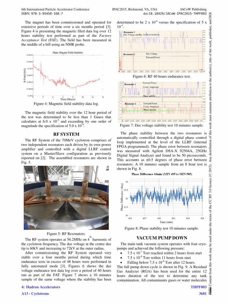
The magnet has been commissioned and operated for
extensive periods of time over a six months period [3].
Figure 4 is presenting the magnetic filed data log over 12
hours stability test performed as part of the Factory
Acceptance Test (FAT). The field has been measured in
the middle of a hill using an NMR probe.
Figure 4: Magnetic field stability data log.
The magnetic field stability over the 12 hour period of
the test was determined to be less than 1 Gauss that
calculates at 6.0 x 10⁻⁵
and exceeding by one order of
magnitude the specification of 5.0 x 10⁻⁴
.
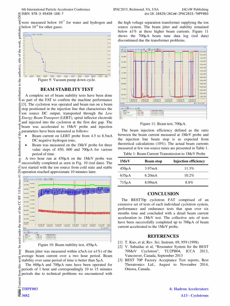
RF SYSTEM
The RF System of the 70MeV cyclotron comprises of
two independent resonators each driven by its own power
amplifier and controlled with a digital LLRF control
system on a Master/Slave configuration as previously
reported on [2]. The assembled resonators are shown in
Fig. 5.
Figure 5: RF Resonators.
The RF system operates at 56.2MHz on 4th
harmonic of
the cyclotron frequency. The dee voltage at the centre dee
tip is 60kV and increasing to 72kV at the outer radius.
After commissioning the RF System operated very
stable over a four months period during which time
endurance tests in excess of 48 hours were performed in
fully automated mode [3]. Figures 6 shows the dee
voltage endurance test data log over a period of 40 hours
run as part of the FAT. Figure 7 shows a 10 minutes
sample of the same voltage where the stability has been
determined to be 2 x 10⁻⁴
versus the specification of 5 x
10-4
.
Figure 6: RF 40 hours endurance test.
Figure 7: Dee voltage stability test 10 minutes sample.
The phase stability between the two resonators is
automatically controlled through a digital phase control
loop implemented at the level of the LLRF (internal
FPGA programmed). The phase error between resonators
was measured with Agilent DSA-X 92504A, 25GHz
Digital Signal Analyzer and found to be 50 picoseconds.
This accounts as ±0.5 degrees of phase error between
resonators. A 10 minutes sample from an 8 hour test is
shown in Fig. 8.
Figure 8: Phase stability test 10 minutes sample.
VACUUM PUMP DOWN
The main tank vacuum system operates with four cryo-
pumps and achieved the following pressure: 7.5 x 10⁻⁷
Torr reached within 2 hours from start 7.5 x 10⁻⁸
Torr within 11 hours from start Falling below 7.5 x 10⁻⁸
Torr after 12 hours.
The full pump down cycle is shown in Fig. 9. A Residual
Gas Analyzer (RGA) has been used for the entire 12
hours duration of the test to determine any tank
contamination. All contaminants gases or water molecules
6th International Particle Accelerator Conference IPAC2015, Richmond, VA, USA JACoW PublishingISBN: 978-3-95450-168-7 doi:10.18429/JACoW-IPAC2015-THPF003
4: Hadron AcceleratorsA13 - Cyclotrons
THPF0033681
Cont
entf
rom
this
wor
km
aybe
used
unde
rthe
term
soft
heCC
BY3.
0lic
ence
(©20
15).
Any
distr
ibut
ion
ofth
isw
ork
mus
tmai
ntai
nat
tribu
tion
toth
eau
thor
(s),
title
ofth
ew
ork,
publ
isher
,and
DO
I.
were measured below 10-7
for water and hydrogen and
below 10-8
for other gases.
Figure 9: Vacuum pump down cycle.
BEAM STABILITY TEST
A complete set of beam stability tests have been done
as part of the FAT to confirm the machine performance
[3]. The cyclotron was operated and beam run on a beam
stop positioned in the injection line that characterises the
ion source DC output, transported through the Low
Energy Beam Transport (LEBT), spiral inflector electrode
and injected into the cyclotron at the first dee gap. The
beam was accelerated to 1MeV probe and injection
parameters have been measured as follows: Beam current on LEBT probe from 4.5 to 8.5mA
DC negative hydrogen ions, Beam was measured on the 1MeV probe for three
value steps of 450, 600 and 700µA for various
period of time.
A two hour run at 450µA on the 1MeV probe was
successfully completed as seen in Fig. 10 (red data). The
test started with the ion source from cold state and stable
operation reached approximate 10 minutes later.
Figure 10: Beam stability test, 450µA.
Beam jitter was measured within ±5uA (or ±1%) of the
average beam current over a two hour period. Beam
stability over same period of time is better than 5µA.
The 600µA and 700µA runs have been operated for
periods of 1 hour and correspondingly 10 to 15 minutes
periods due to technical problems we encountered with
the high voltage separation transformer supplying the ion
source system. The beam jitter and stability remained
below ±1% at these higher beam currents. Figure 11
shows the 700µA beam tune data log (red data)
discontinued due the transformer problems.
Figure 11: Beam test, 700µA.
The beam injection efficiency defined as the ratio
between the beam current measured at 1MeV probe and
the injection line beam stop is as expected from
theoretical calculations (10%). The actual beam currents
measured at few ion source tunes are presented in Table 1.
Table 1: Beam Current Transmission to 1MeV Probe
1MeV Beam stop Injection efficiency
450µA 3.97mA 11.3%
635µA 6.20mA 10.2%
715µA 8.09mA 8.8%
CONCLUSION
The BEST70p cyclotron FAT comprised of an
extensive set of tests of each individual cyclotron system,
performance and endurance tests that span over six
months time and concluded with a detail beam current
acceleration to 1MeV test. The collective sets of tests
have been successfully completed up to 700µA of beam
current accelerated to the 1MeV probe.
REFERENCES
[1] T. Kuo, et al, Rev. Sci. Instrum. 69, 959 (1998).
[2] V. Sabaiduc et al, “Resonator System for the BEST 70MeV Cyclotron”, TU2PB04, ICCA 2013, Vancouver, Canada, September 2013
[3] BEST 70P Factory Acceptance Test reports, Best
Theratronics Ltd., August to November 2014,
Ottawa, Canada.
6th International Particle Accelerator Conference IPAC2015, Richmond, VA, USA JACoW PublishingISBN: 978-3-95450-168-7 doi:10.18429/JACoW-IPAC2015-THPF003
THPF0033682
Cont
entf
rom
this
wor
km
aybe
used
unde
rthe
term
soft
heCC
BY3.
0lic
ence
(©20
15).
Any
distr
ibut
ion
ofth
isw
ork
mus
tmai
ntai
nat
tribu
tion
toth
eau
thor
(s),
title
ofth
ew
ork,
publ
isher
,and
DO
I.
4: Hadron AcceleratorsA13 - Cyclotrons