
Austin Morris1100 Handbook
171
CN Y I ct trt .E ct y = 11OO Mk 2,3,1 3OO Mk 1,2,3, America 1968-T 4 Autobook By Kenneth Ball Associate Member. Gurld of Motorino Writers and the Autopress Team of Technical-Writers Austin, Morris 1 1 00 Mk2,3, 1 968 -73 Austin, Morris 1300 Mk 1, 2,3,GT 1 968-74 Austin America 1968-72 M.G.1 1 00 Mk2,1 300 Mk 1 ,2,3,1 968-71 Rifey 1 1 00 Mk2,1 300Mk 1 ,2,1968-69 Vanden-Plas Princess 1100 Mk2,1300 1968-74 Wolseley 1 1 00 Mk2,1 300 Mk'1 ,2,3,1 968-73 Autopress Ltd.Golden Lane Brighton BN1 2QJ England
-
Upload
csharpplus -
Category
Documents
-
view
173 -
download
19
Transcript of Austin Morris1100 Handbook

CNY
I
cttrt
.Ecty=
11OO Mk 2,3,1 3OO Mk 1,2,3, America 1968-T 4AutobookBy Kenneth BallAssoc ia te Member . Gur ld o f Motor ino Wr i te rsand the Autopress Team o f Techn ica l -Wr i te rs
Austin, Morris 1 1 00 Mk2,3, 1 968 -73Austin, Morris 1300 Mk 1, 2,3,GT 1 968-74Austin America 1968-72M.G.1 1 00 Mk2,1 300 Mk 1 ,2,3,1 968-71Rifey 1 1 00 Mk2,1 300 Mk 1 ,2,1968-69Vanden-Plas Princess 1100 Mk 2,1300 1968-74Wolseley 1 1 00 Mk 2,1 300 Mk'1 ,2,3,1 968-73
Autopress Ltd. Golden Lane Brighton BN1 2QJ England
The AUTO BOO K ser ies o f Workshop Manua lsis the la rges t in the wor ld and covers themajor i t y o f Br i t i sh and Cont inenta l motor cars ,as we l l as a l l ma jor Japanese and Aust ra l ianmode ls . For a fu l l l i s t see the back o f th ism a n u a l .
C O N T E N T S
ln t roduc t ion
Acknowledgement
Chapter 1 The Eng ine
Chapter 2 The Fuel System
Chapter 3 The lgni t ion System
Chapter 4 The Cool ing System
Chapter 5 The C lu tch
Chapter 6 The Synchromesh Transmission
Chapter 7 Automat ic Transmiss ion
Chapter 8 The Drive Shafts andSuspens ion
Chapter 9 The Steering Gear
Chapter 10 The Brak ing Sys tem
Chapter 1 1 The Electr ical System
Chapter 12 The Bodywork
Append ix
2tr
496 5
6 1
61
l 9
9 1
1 0 5
1 1 1
121
145

t s B N 0 8 5 1 4 7 4 8 1 0
F i r s t Ed i t i on 1970Rep r i n ted 1971Second Ed i t i on , f u l l y r ev i sed 1971Th i rd Ed i t i on , f u l l y r ev i sed 1972Repr inted 1972Fou r th Ed i t i on , f u l l y r ev i sed 1973Rep r i n ted 1 973F i f t h Ed i t i on , f u l l y r ev i sed 1974Rep r i n ted 1974
OAu top ress L td 1974
Al l r ights reserved. No part of th is publ icat ion may bereproduced, stored in a retr ieval system, or t ransmit ted in
any form or by any means, e lectronic, mechanical ,photocopying, recording or otherwise, wi thout the pr iorpermission of Autopress Ltd.
Printed and bound in Brighton England for Autopress Ltd by G Beard & Son Ltd
A C K N O W L E D G E M E N T
Mv thanks are due to The Bri t ish Leyland Motor Corporat ion Ltd for theiruns t in ted co-opera t ion and a lso fo r supp ly ing da ta and i l lus t ra t ions .
I am a lso gra te fu l to a cons iderab le number o f owners who have d iscussed the i rcars a t len l tn and many o f whose suggest ions have been inc luded in th is manua l .
Kenneth Bal lAssociate Membel Gui ld of Motor ing Wri tersDi tch l ing Sussex Eng land.
I N T R O D U C T I O N
Th is do - i t - you rse l f Workshop Manua l has been spec ia l l y w r i t t en f o r t he ownerwho w ishes to ma in ta in h i s ca r i n f i r s t c l ass cond i t i on and to ca r r y ou t h t s ownse rv i c i ng and repa i r s . Cons rde rab le sav ings on ga rage cha rges can be made , andone can d r i ve i n sa fe t y and con f i dence know ing the work has ! ; ecn donepropef ly .
Comprehens i ve s tep -by -s tep i ns t ruc t i ons and i l l us t ra t i ons a re g i ven on a i i d i s -man t l i ng , ove rhau l i ng and assemb l i ng ope ra t i ons . Ce r ta in assemb l i es requ i rethe use o f expens i ve spec ia l t oo l s , t he pu rchase o f wh i ch wou ld be un jus t i f i ed .l n t hese cases i n fo rma t i on i s i nc luded bu t t he reade r i s recommended to handthe un i t t o t he agen t f o r a t t en t i on .
Th roughou t t he Manua l h in t s and t i ps a re i nc luded wh ich w i l l be f oundinva luab le , and the re i s an easy to f o l l ow fau l t d i agnos i s a t t he end o f eachchap te r .Whi ls t everv care has been taken to ensure correctness of in format ton i t isobviously not possib le to guarantee complete f reedom from errors or to acceptl i ab i l i t y a r i s i ng f r om such e r ro rs o r om iss ions .
l ns t ruc t i ons may re fe r t o t he r i gh thand o r l e f t hand s ides o f t he veh i c l e o r t hecomponen ts . These a re t he same as the r i gh thand o r l e f t hand o f an obse rve rs tand ing beh ind the ca r and l ook ing fo rwa rd .
CHAPTER 1
T H E E I U G I N E
1 : 11 : 21 : 31 : 41 : 51 : 61 : 71 : 8
Desc r i p t i onRemov ing eng ine and synch romesh gea rboxRemov ing eng ine and au toma t i c t r ansm iss i onRemov ing and re f i t t i ng t he cy l i nde r headSe rv i c i ng t he head and va l ve gea rSe rv i c i ng t he va l ve t im ing gea rSe rv i c i ng t he camsha f tRemov ing and rep lac i ng t he f l ywhee l andc lu t ch
1 : 9 Remov ing t he f l ywhee l hous ing1 : 10 Remov ing t he synch romesh t r ansm iss i on1 : 11 Se rv i c i ng t he c ranksha f t p r ima ry gea r1 : 12 P i s t ons and connec t i ng rods . 1098cc eng ine1 : 13 C ranksha f t and ma in bea r i ngs . Synch romesh
gea rbox
1 : 1 Desc r i p t i on
The eng ines f i t t ed t o t he ca rs cove red by t h i s manua la re p roduced i n seve ra l ve r s i ons acco rd i ng t o eng inecapac i t y , ca rbu re t t e r i ns ta l l a t i on and t r ansm iss i on t ype -au toma t i c o r synch romesh . I n a l l cases t he eng ine i s con -structed in uni t wi th the t ransmission system and in thrschapter ment ion wi l l be made only of those operat ionsaf fect ing the engine. Where the type of t ransmission systemrequ i res a d i f f e ren t p rocedu re t he ope ra t i ons w i l l becove red unde r app rop r i a te head ings .
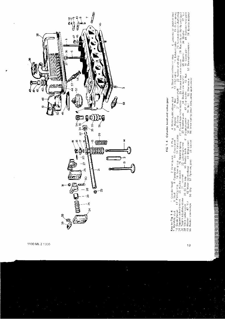
The eng ine and t r ansm iss i on un i t i s shown i n tw in ca r -bu re t t e r f o rm rn t he sec t i ona l v i ew o f F IG 1 : 1 . The eng inei s a f ou r - cy l i nde r un i t o f e i t he r 1 098 o r 1275 cc capac i t ywi th oushrod oDerated overhead valves and rs mountedtransversely across the f ront of the car, dr iv ing the f rontwhee l s t h rough two sho r t d r i v i ng sha f t s . De ta i l s o f t hebore s ize, st roke and compression ratros wi l l be found inTechn i ca l Da ta a t t he end o f t he manua l .
The va l ves , se t i n l i ne i n t he l e f t hand s i de o f t he cy l i nde rhead, have oi l seals f i t ted to the stems and are givenc lea rance ad jus tmen t by an ad lus tab le sc rew and l ocknu t
1 1 0 0 M k 2 1 3 0 0
F l ywhee l s t a r t e r r i ng . Synch romesh gea rboxThe o i l pump . Synch romesh gea rboxLub r i ca t i on . O i l f i l t e r and re l i e f va l veCrankcase em iss i on con t ro lV a l v e t i m i n gReassemb l i ng t he eng ineVa l ve rocke r ad jus tmen tOpe ra t i ons a f f ec ted by au toma t i ct r ansm iss i onSpec ia f ope ra t i ons on 1275 cc eng ineO i l con t ro l p i s t on r i ngsExhaus t em iss i on con t ro lEng ine s teady rodFau l t d i agnos i s
1 : 1 41 : 1 51 : 1 61 : 1 7
: 1 8: 1 9: 2 Q: 2 1
: 2 2: 2 3: 2 4: 2 5: 2 6
i n t he rocke r a rm . The camsha f t , r unn ing i n t h ree wh i t e -metal bear ings, is dr iven by chain f rom the crankshaft wi thsyn the t r c r ubbe r r i ngs ac t i ng as cha in s i l ence rs and t en -s ioners. The oi l pump is dr iven f rom the other end of thecamshaft and also the dist r ibutor through a t ransversesha f t .
The pistons have three compression r ings and ones lo t t ed o i l con t ro l r i ng . Gudgeon p i ns a re f u l l y f l oa t i ng i nt he 1098 cc eng ine , and p ressed i n t o t he sma l l end o f t heconnec t i ng rod i n t he 1275 cc eng ine . The connec t i ngrod bea r i ngs a re s tee l - backed she l l s w i t h l ead / i nd ium o rl ead / t i n l i n i ngs .
The o i l supp l y f o r t he eng ine , gea rs an<J d i f f e ren t i a l i scarr ied in the t ransmission case below the crankcasewhence i t is drawn by the rotary o i l pump at the rear endo{ the crankcase and del ivered to a fu l l f low external f i l ter ,and on t h rough d r i l l ed passages t o t he ma in , b i g -end andcamshaft bear ings. The overhead valve gear is fed atreduced pressure f rom the f ront camshaft bear ing, the ot lr e t u rn i ng t o t he sump down t he push rod ho les , l ub r i ca t i ngthe tappets on the way.
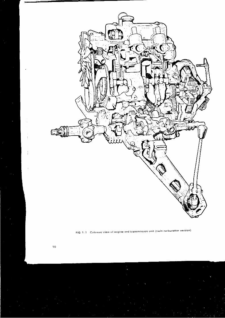
F I G 1 : 1 C u t a w a y v i e w o f e n g i n e a n d t r a n s m i s s i o n u n i t ( t w i n c a r b u r e t t e r v e r s r o n )
\
I
\ .,,,
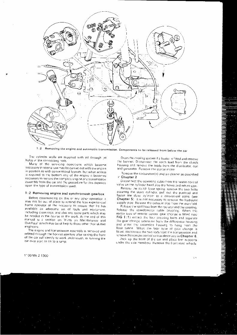
2 R e m o v i n g t h e e n g i n e a n d a u t o m a t i c t r a n s m i s s i o n . c o m p o n e n t s t o b e r e l e a s e d i r o m b e l o w t h e c a r
The cy l i nde r wa l l s a re supp l i ed w i t h o i l t h rough j e tho les i n t he connec t i ng rods .
Many o f t he se rv r c i ng ope ra t j ons wh i ch becomenecessa ry i n no rma l use may be ca r r j ed ou t w i t h t he eng inein pos i t i on as w i t h conven t i ona l l ayou t s , bu t when ac i essi s r equ i r ed t o t he bo t t om end o f t he eng ine i t becomesnecessa ry t o r emove t he comp le te eng ine and t r ansm iss i onassemb ly f r om the ca r and t he p rocedu re f o r t h i s dependsupon t he t ype o f t r ansm iss i on used .
1 : 2 R e m o v i n g e n g i n e a n d s y n c h r o m e s h g e a r b o x
Be fo re commenc ing on t h i s o r any o the r ope ra t i on i tmay no t be ou t o f p l ace t o r em ind t he l ess expe r i encedhome ope ra to r o f t he necess r t y t o ensu re t ha l he hasava i l ab l e an adequa te se t o { t oo l s and equ ipmen r .r nc l ud ing c l ean rags , and a l so any spa re pa r t s wh i ch maybe needed i n t he cou rse o f t he wo rk . A t t he end o f t h r sm a n u a t r s a s e c t t o n o n ' H i n t s o n M a i n t e n a n c e a n dOve rhau l 'wh i ch may be o f he lp t o t hose o the r t han sk j l r eoeng i nee rs .
The eng ine and t r ansm iss ron assemb ly i s r emoved andre f i t t ed t h rough t he bonne t ape r t u re a f t e r r a i s i ng t he f r on to f t he ca r su f f i c i en t l y t o wo rk unde rnea th , o r r unn ing t heca r ove r a p i t o r on t o a r amp .
1 1 0 0 M k 2 1 3 0 0
Dra in t he coo l i ng sys tem i f a hea te r i s f i t t ed and removethe bonne t . D i sconnec t t he ea r t h l ead f r om the c l u t chhous ing and remove t he l eads f r om the d i s t r i bu to r . co t tand gene ra to r Remove t he s ta r t e r mo to r .
Remove t he ca rbu re t t e r ( s ) and a i r c l eane r as desc r i oedi n C h a p t e r 2 .
D i sconnec t t he ope ra t i ng cab le f r om the hea te r con t ro lva l ve on t he cy l i nde r head a l so t he hoses and re tu rn p i pe .
Re lease t he c l u t ch l eve r sp r rng , r en tove t he two bo l t ssecu r i ng t he s l ave cy l i nde r , pu l l ou t t he push rod andfas ten t he s l ave cy l i nde r 1o a conven ien t po in t ( seeChap te r 5 ) . l t i s no t necessa ry t o r emove t he hyd rau l i csupp l y p i pe . Re lease t he exhaus t p i pe f r om the man i f o ro .
Re lease t he sp i i l hose f r om the rad j a t o r and t he cow l i ng .Re lease t he speedome te r cab le coup l i ng . When t heea r l r e r t ype o f r emo te con t ro l gea r chanqe i s f i t t ed ( seeF IG 1 : 1 ) ex t r ac t t he f ou r secu r i ng bo l t s and sepa ra tethe gea r change ex tens ion f r om the d i f f e ren t i a l hous rngand a i l ow t he ex tens ion hous rng t o hang f r om {hef l oo r t unne l . When t he l a t e f t ype o f gea r change i sf i t t ed , d i sconnec t t he two rods f r om the t r ansm iss i on andremove t he f emo te con t ro l un i t as desc r i bed i n Chap te r 6 .
Jack up t he f r on t o f t he ca r and p l ace f i rm suppo r t sunde r t he s rde members . Remove t he f r on t r oad whee l s .
1 1
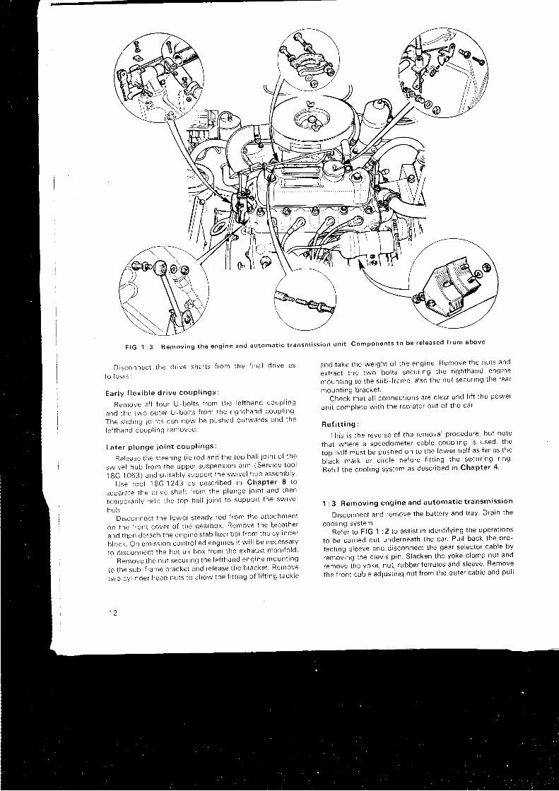
F I G 1 : 3 R e m o v i n g t h e e n g i n e a n d a u t o m a t i c t r a n s m i s s i o n u n i t
Disconnec t t he d r i ve sha f t s f r om the f i na l d r i ve as
fo l l ows I
E a r l y f l e x i b l e d r i v e c o u P l i n g s :
Remove a l l f ou r U -bo l t s f r om the l e f t hand coup l i ng
and t he two ou te r U 'bo l t s f r om the r i gh thand coup l l ng '
The s l i d i ng l o i n t s can now be pushed ou twa rds and t he
le f t hand coup l i ng removed
L a t e r p l u n g e j o i n t c o u P l i n g s :
Re lease t he s tee r i ng t i e r od and t he t op ba l l Jo i n t o f t he
sw ive l hub f r om the uppe r suspens ion a rm (Se rv i ce t oo l
1 8 G . 1 0 6 3 ) a n d s u i t a b l y s u p p o r t t h e s w i v e l h u b a s s e m b l y
Use t oo l 18G.1243 as desc r i bed i n Chap te r 8 t o
sepa ra te t he d r i ve sha f t f r om the p l unge l o i n t and t hen
tempo ra r i l y r e f i t t he t op ba l l l o i n t t o suppo r t t he sw i ve l
n u D .D i sconnec t t he I owe r s t eady rod f r om the a t t achmen t
on t he f r on t cove r o f t he gea rbox . Remove t he b rea the r
and t hen de tach t he eng ine s tab i l i ze r ba r f r om the cy l i nde r
b l ock . On em iss i on con t ro l l ed eng ines i t w i l l be necessa ry
to d i sconnec t t he ho t a i r box f r om the exhaus t man i f o l d
Remove t he nu t secu r i ng t he l e f t hand eng rne moun t t ng
to t he sub f r ame b racke t and re l ease t he b racke t Remove
two cy l i nde r head nu t s t o a l l ow t he { i t t i ng o f I i f t i ng t ack l e
1 2
and t ake t he we igh t o f t he eng ine Remove t he nu t s and
ex t rac t t he two bo l t s secu r i ng t he r i gh thand eng lne
moun t i ng t o t he sub f r ame , a l so t he nu t secu r l ng t ne rea r
moun t i ng b racke t .Check t ha t a l l connec t i ons a re c l ea r and l i f t t he power
un i t comp le te w i l h t he rad la to r ou t o f t he ca r '
Re f i t t i ng :
Th i s i s t he reve rse o f t he remova l p rocedu re ' bu t no te
tha t whe re a speedome te r cab le coup l i ng i s used ' t he
too ha l f mus t be pushed on t o t he l owe r ha l f as f a r as t he
b lack mark o r c i r c l e be fo re f i t t i ng t he secu r i ng r i ng
Re f i l l t he coo l i ng sys tem as desc r i bed i n Chap te r 4
1 : 3 Remov ing eng ine and au toma t i c t r ansm iss i on
Disconnect and remove the bat tery and t ray Drain the
coo l r ng sys l em.Re fe r t o F IG 1 : 2 t o ass i s t i n i den t i f y i ng t he ope ra t rons
to be ca r r i ed ou t unde rnea th t he ca r ' Pu l l back t he p ro -
tect ing s leeve and disconnect the gear selector cable by
re .ou ing t he c l ev i s p i n S lacken t he yoke c l amp nu t and
,"mou" ih" yoke, nut , rubber ferru les and s leeve Remove
the f r on t cab le ad jus t i ng nu t f r om the ou te r cab le and pu l l
C o m p o n e n t s t o b e r e l e a s e d f r o m a b o v e
f - u > = :
7 ' i r ! cj : ! i - o I to ; ! ; = t
! U ! ; D O! >
3 3 3 € * : o -3 i l i . i s: i ; 3 " o9 B : a o- ? " 5 ; . '
> A t o :@ ; a y
; 2 2 = _: f
r x - = o -J U : '
: $ o ; B o 5
i E ! o : =; ! e m \ F: , -' q : o
: ; x >O E E : i :
! t l t ? - s E- : = ' ? i d : :
: - > F
@ l
: d : ;; N € i N i
: E - * o l !: , ' 1 : r : ' ^ ?a a z : r < = |
L { o , i * o
> : F : = ^ . 2 -
S 5 3 o = i
Y - - = : i - o - a
Q E a U T J : Ec { = - g 3 : € !:
- . : r ; ; = -
r 5 0 4 o o) , r O
v i
- p :s : a " _ - u. L - o : a = - <r : > ! i 9 :
I 9 > ; Y . I "r , 9 o 9 ' ) { n P
v - = . - ; _ '
* : . i : : go g , ^ ) )
? - N ; - o
i . ? Y l :) : = - o :N a : o ; o
: w : = - =. : - r ; o 5 r- - u o o n
t o _ .
- : L ^ ) = 5 ?
i " P
- o o- - L r !
> : a " oO O c
L _ t
N I : :
S - 9 - o
+ - : : q ; - !- : 9 ? - = _ : :. " = : 8 9
_o ! a - - : : -
q U : : ; O T ^
o - = : E + ; 3 €l * ' r ; ; ; = ;o - o s O @ @ 6
Y r - N o o s 6
s = ? q T J,,d dx
1 1 0 0 M k 2 1 3 0 0
P#P",-
8 4 2
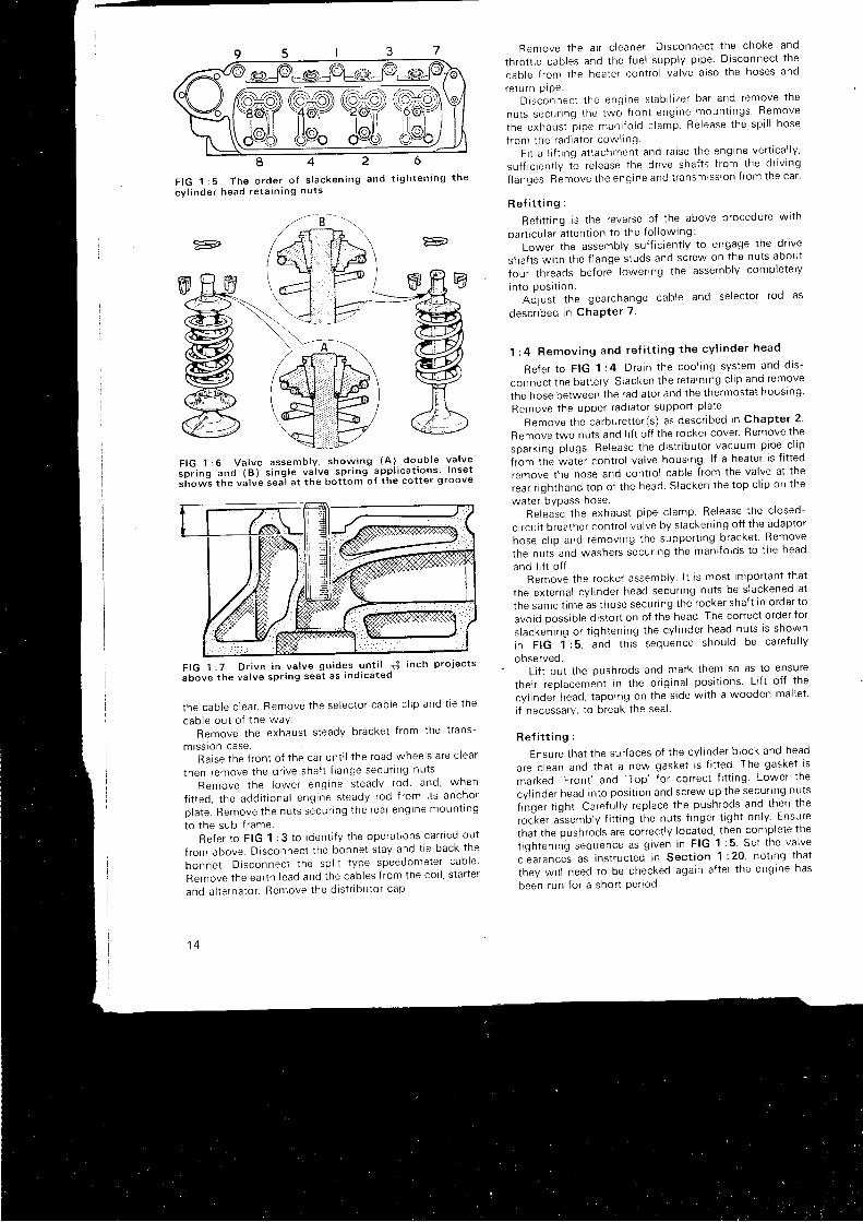
F I G 1 : 5 T h e o r d e r o f s l a c k e n i n g a n d
c y l i n d e r h e a d r e t a i n i n g n u t s
Remove t he a i r c l eane r . D i sconnec t t he choke and
th ro t t l e cab les and t he f ue l supp l y p i pe D i sconnec t t he
cab le f r om the hea te r con t ro l va l ve a l so t he hoses and
re tu rn p iPe .D i sconnec t t he eng ine s tab l l i ze r ba r and remove t he
nu t s secu r i ng t he two f r on t eng ine moun t i ngs ' Remove
the exhaus t p i pe man i f o l d c l amp Re lease t he sp i l l hose
{ rom the rad ia to r cow l l ngF i t a l i f t i ng a t t achmen t and ra i se t he eng ine ve r t i ca l l y '
su f f i c i en t l y t o r e l ease t he d r i ve sha f t s f r om the d r i v i ng
f l an -oes . Remove t he eng ine and t r ansm iss i on f r om the ca r '
R e f i t t i n g :
Ref i t t ing is the reverse of the above procedure wi th
pa r t i cu l a r a t t en t i on t o t he f o l l ow ing :
Lower the assembly suf f ic ient ly to engage the dr ive
shafts wi th the f lange studs and screw on the nuts about
{our threads before lower ing the assembly completely
i n to pos t t t on .Ai just the gearchange cable and selector rod as
desc r i bed i n ChaP te r 7 .
1 : 4 Remov ing and re f i t t i ng t he cy l i nde r head
Re fe r t o F IG ' l : 4 . D ra i n t he coo l i ng sys tem and d i s -
connect the bat tery. Slacken the reta in ing c l ip and remove
the hose be tween t he rad ia to r and t he t he rmos ta l hous ing
Remove t he uppe r r ad ia to r suppo r t p l a te
Remove t he ca rbu re t t e r ( s ) as desc r i bed i n Chap te r 2 '
Remove two nuts and l i f t of f the rocker cover ' Remove the
spa rk i ng p l ugs . Re lease t he d i s t r i bu to r vacuum p ipe c l l p
t iom tne waGr contro l valve housing l f a heater is f i t ted
remove the hose and contro l cable f rom the valve at the
rear r ighthand top of the head Slacken the top c l ip on the
water bvpass hoseRe lease t he exhaus t p i pe c l amp Re lease t he c l osed
circurt breather contro l valve by s lackening of f the adaptor
hose c l ip and removing the support ing bracket Remove
the nuts and washers secur ing the mani fo lds to the head
and l i f t of f .Remove the rocker assembly l t is most important that
the external cy l inder head secur ing nuts be s lackened at
the same t ime as those secur ing the rocker shaf t in order to
avoid possib le d istor t ion of the head The correct order for
s l acken ing o r t i gh ten ing t he cy l i nde r head nu t s l s shown
in F IG 1 :5 , and t h i s sequence shou ld be ca re fu l l y
observed.Li f t out the pushrods and mark them so as to ensure
their replacement in the or ig inal posi t ions Li f t of { the
cyl inder head, tapping on the s ide wi th a wooden mal let '
i f necessary, to break the seal
R e f i t t i n g :
Ensure that the surfaces of the cyl inder b lock and head
are c lean and that a new gasket is f i t ted The gasket is
marked 'Front '
and 'Top' for correct f i t t ing Lower the
cy l i nde r head i n t o pos i t i on and sc rew up t he secu r i ng nu t s
f inger t ight . Careful ly replace the pushrods and then the
roc-ker a isembly f i t t ing the nuts f inger t ight only Ensure
that the pushrods are correct ly located, then complete the
t i gh ten ing sequence as g i ven i n F IG 1 : 5 -Se t t he va l ve
" l ""arunc" i as instructed in Sect ion 1 :20. not ing that
they wi l l need to be checked again af ter the engine has
been run for a short Per iod
6
t i g h t e n i n g t h e
--; -t ' \
=
F I G 1 : 6 V a l v e a s s e m b l y , s h o w i n g ( A ) . d o u b l e v a l v e
s o r i n q a n c l ( B ) s i n g l e v a l v e s p r i n g a p p l i c a t i o n s l n s e t
s 'how-s the va lve sea l a t the bo t tom o f the co t te r 9 roove
t he cab le c l ea r . Remove t he se lec to t cab le c l i p and t l e t he
cab le ou t o f t he waYRemove the exhaust steady bracket f rom the t rans-
m tss ron case .Ra i se t he f r on t o f t he ca r un t i l t he r oad whee l s a re c l ea r
t hen remove t he d r i ve sha f t f l ange secu r t ng nu t s '
Remove t he l owe r eng ine s teady rod , and , when
f i t t ed , t he add i t i ona l eng ine s teady rod f r om i t s ancho r
p la te . Remove t he nu t s secu r i ng t he rea r eng tne moun t i ng
to t he sub f r ame .Refer to FIG 1 :3 to ident i fy the operatrons carr led out
f rom above. Disconnect the bonnet stay and t ie back the
bonne t . D i sconnec t t he sp l i t t ype speedome te r cab le
Remove the earth lead and the cables f rom the cor l ' s tar ter
and a l t e rna to r . Remove t he d i s t r i bu to r cap
1 4
F I G 1 : 7 D r i v e i n v a l v e g u i d e s u n t i l 1 ; i n c h p r o 1 e c t s
a b o v e t h e v a l v e s p r i n g s e a t a s i n d i c a t e d
, : : > : o
+ a - 6 6
: i 3 ; Ft r ( 9
- F O O :
N N = ' -> ^ 5 :
99 E',e o
H - E - -
- o o
i r o r i ?, ^ ; N 8 d- : =
! r - g
f f \ - '
- : o
! N : : O
^ - - o < =
F 3 i -a 7 - o
; N Oo o
> 6
E , E E s iF 9 = ; e ;z . 9 - F : 3 ao i 9 > : ?o > : ^ v * i
t s s 9 r - Q ^O X U Y
a > ; : N
o - , o i
E . 3 t ; E' : o 6 0 o oC
- ! 6
a - 9 0o 9 E ( J
! o ; d :
c : 9 ? " ?; e ? ; i: c > o - '
h o ; - : o
. = \ ; 6 -
| 6 o E t i. ! u m o
o o ) . : - 6
e z r - r
( , N 6= F-
- : N
- - . : - -o - > = o o
: - - : ; c
c - = 6 " .o -L tr ;
- ! x r ^
: 3 - R 9 -- ;F ; 2 '
* E ; = . !> * l 2 E P- i o o o P
! . * > io o , ^
* O _ - . SF a Y !- ' 9 a
o ) o ! :L ! - c 5
; : 'A 9 a.H9 - o s + sY @ - N o s
F
1 1 0 0 M k 2 1 3 0 0

F IG ' l : 9 T im ing gea r assemb ly show ing pos i t i on o f t hetwo t im ing marks
The remainder of the ref i t t ing operat ion is a reversal oft he remova l p rocedu re .
Re f i l l and check t he coo l i ng sys tem. Check t he f ue lsys ten r . S ta r t t he eng ine and run f o r some m inu tes a tworKrng temperature then check the t ightness o{ thecy l r nde r head nu t s and t he rocke r c l ea rances .
On the Aust in America th is operat ion must be fo l lowedby an exhaus t em iss i on check .
1 : 5 Se rv i c i ng t he head and va l ve gea r
Hav ing removed t he cy l i nde r head , p l ug t he wa te rwaysIn the top of the block wi th rag to prevent the entry of anyfo re i gn ma t t e r . Sc rape t he ca rbon f r om the combus t i onspaces In the head before removing the valves to avoiddamage t o t he va l ve sea t s .
The va l ve assemb ly o f t he 1098 cc eng ine i s shown i nF IG 1 : 6 f he 1275 cc eng ine i s s l i gh t l y d i f f e ren t and t heva l ve assemb ly i s de ta i l ed i n Sec t i on 1 : 22 . Remove t hecot ter c l ip and wi th a compressor tool compress the valvespf lngs and remove the spl i t cot ters. Release the com-p resso r , r emove t he re ta i n i ng cap , sp r i ngs and rubbe rsea l i ng r i ng . Remove t he va l ve and mark i t f o r r eassemb lyi n i t s o r i g rna l pos i t i on .
Exam ine t he va l ves f o r p i t t i ng , bu rn i ng , c rack i ng o rd i s t o r t i on and rep lace any f ound t o be f au l t y . Those va l veswhose condL t i on i s good may be g round i n by us i ng t hefo l l ow ing p rocedu re , wh i ch a l so shou ld be used whenf i t t ing new valves or when the head seats have been re-cut .
W i t h a s rna l l amoun t o f va l ve g r i nd ing pas te app l i ed t othe seat f ine grade i f the surfaces are good, otherwtsemed ium g rade f i r s t and f i n i sh i ng w i t h f i ne -p l ace t heva l ve on i t s sea t i ng and by means o f a suc t i on g r i nd ingtool rotate the valve f rom side to s ide and occasional lyl i f t ing to a new posi t ion unt i l both seats have a smoothmatt qrev f in ish. Clean al l t races of paste f rom bornsu r f aces . l f t he va l ve sea t s i n t he head a re t oo bad l v
1 6
worn f o r g r i nd rng t o be f u l l y e f f ec t i ve , spec ia l va l ve sea ti nse r t s can be { i t r ed by t he Se rv i ce S ta t i on . Somecy l i nde r heads n ray have i nse r t s f i t t ed as o r i g i na l equ ip -men t .
Exam ine t he va l ve gu rdes . and t f t hey a re bad l y wo rn o rscored they shouid be renewed The dr i f t used for thepu rpose o f d r i v i ng ou t t he o i d va l ve gu ide shou lo oea ha rdened s tee l punch . { i n ch rn d rame te r and a t l eas t 4rnches l ong , w r t h a l oca t i ng sp tgo t + r nch i n d i ame te rmach rned on one end f o r 1 i nch t o engage t he bo re o f t hegu ide The new gu ides shou ld be d r i ven t n f r om the t opo f t he cy l i nde r head , i n l e t gu ides w i t h t he l a rges t chamfe ra t t he t op , and exhaus t gu rdes w i t h t he coun te rbo re endsat the bot tom. When f i t ted the gr-r ides should project - | !i n ch above t he mach ined va ve sp r i ng sea t i ng as showni n F I G 1 : 7
Str ipping the rocker gear wi l l be assisted by reference toF IG 1 :4 Remove t he g rub sc rew 32 f r om the moun t i ngb racke t 24 . W i t hd raw the sp l r p rns and washe rs and s l i deo f f a l l t he r ema in i ng pa r t s no t i ng ca re i u l l y t he pos i t i onsthey occup ied f o r l a t e r r eassemb lV The p rocedu re f o r t he12 -75 cc eng ine i s s i n r j l a r , bu t i t w i l l be seen t ha t t he re a res i x d i s t ance p teces , one on each s i de o f t he two ou te rrockers and one on the bracket s ide of the two middlerockers.
Two types of rocker are used, one being a forging andthe other of pressed steel . When the rocker bushes becomeworn r t t s poss tb l e t o r enew the bush o f t he f o rged t ypeassemb ly . The new bush shou ld be p ressed i n t o t herocke r bo re w r tn t he bu t t l o i n t pos i t i oned a t t he t op o f t heb o r e a n d a h o l e m u s t b e d r i i l e d w i t h a N o . 4 7 d r i l l t oco rnc i de w i t h t he ho le i n t he t op o f t he rocke r ba r re l .F i na l l y bu rn i sh ream the bo re o f t he bush t o .5630 to .5635r n c h .
When reassernbl ing the rocker shaf t assembly f i rs tsecure the f ront mount ing bracket wi th i ts grubscrew,then rep lace t he rema in i ng pa r t s i n t hea r o r i g i na l o rde r onthe sha f t . The sc rewed p l ug i s a t t he f r on t o f t he eng ine .
When remov ing t he ca rbon f r om the p r s ton c rown i t i salways advisable to leave a r ing of carbon adjacent to thecy l i nde r bo re as t h i s w i l l he l p t o ma in ra i n a good sea l andconse rve o i l Th i s may be done by i nse r t i ng an o l d p i s t onr i ng o i t he co r rec t s i ze i n t o t he bo re on t op o f t he p i s l on ,and t hen w i t h a b l un t t oo l r emov ing t he ca rbon w i t h j n t her rng . l t shou ld be s t r essed he re t ha t when remov ingdepos i t s f r om any a l um in i um pa r t s no ha rsh ab ras i ves o remeryc l o th shou ld be used .
The va l ves shou ld be rep laced i n t he same pos i t i on asthey o r i g i na l l y occup ied , un less new va l ves have beenf i t ted, and new spr ings f i t ted i f any do not conform veryc l ose l y t o t he d imens ions g i ven i n Techn i ca l Da ta . Newrubbe r sea l s a l so shou ld be used as shown . L i gh t l ylubr icate the valve stems before insert ion into their guides.
Rep lace t he cy l i nde r head as desc r i bed i n Sec t i on 1 : 4 .
1 : 6 S e r v i c i n g t h e v a l v e t i m i n g g e a r
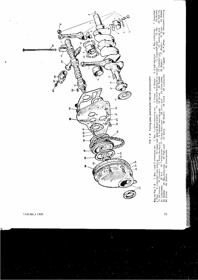
See F IG 1 : 8 . Remove t he rad ia to r as desc r i bed i nChapter 4. Slacken the al ternator at tachment bol ts andremove t he be l t . Un lock t he c ranksha f t pu l l ey l ock i ngwasher, remove the secur ing screw and caref u l ly lever of ft he pu l l ey and damper f r om the c ranksha f t . Remove rnetwo setscrews 29 and 32 and l i f t of f the t iming cover 27.Un lock and remove t he camsha f t cha inwhee l nu t 2b anolockwasher 24. Both chainwheels mav now be levered of f
gent ly, using sui table levers, complete wi th the t imingchain. Note the packrng washers 1 4 behind the crankshaftc h a i n w h e e l 1 2 .
Reassembly is the reverse of the above procedure, butgreat care must be taken to ensure that the two chainwheelsare in a l ignment by checking that the same washers areused. In the event of a new wheel being f i t ted the al ign-rn€nt must be checked by placing a stra ightedge acrossthe s ides of the camshaft wheel teeth and measur ing anygap at the crankshaft wheel . Washers must be added toobtain the correct a l ignment.
A no i sy t im ing cha in may f r equen t l y be cu red byrenewing the tensioner r ings 22, but i f the chain or e i therof the wheels is worn, new parts should be obtained.Never f i t one new part in th is event , but a lways a set oftwo whee l s and a new cha in .
When rep lac i ng t he t im ing cha in ( see F IG 1 :9 ) , se tthe crankshaft wi th i ts keyway at TDC and the camshaftkeyway at approxrmately one o 'c lock as shown. Assemblethe wheels and chain wi th the two t iming marks 1 and 2opposi te to each other. With the wheels in th is posi t ionengage the crankshaft wheel on the crankshaft and rotatethe camshaft unt i l the key on the shaf t and the keyway int he whee l co i nc i de t hen push t he whee l s f u l l y i n t ooos i t i on and secu re t he camsha f t w i t h t he nu t and l ock -washe r .
The oi l thrower is f i t ted wi th the face marked F awavf rom the eng ine .
Fi l l the groove between the l ips of the oi l seal wi ihg rease and i nse r t t he pu l l ey hub squa re l y , t u rn i ng i tc lockwise to avoid damaging the seal . Assemble thecrankshaft pul ley to the cover and push on to the crank-shaf t ensur ing that the keyway on the pul ley is l ined upwith the Woodruf f key on the crankshaft before f inal lyd r i v i ng t he pu l l ey i n t o pos r t r on .
Rep lace t he cove r r e ta i n i ng sc rews and t i gh ten even l y .
1 : 7 Se rv i c i ng t he camsha f t
Remova l :
Remove the rocker gear assembly (see Sect ion 1 :4)and the mani fo lds. Remove the s ide covers and l i f t out thetappe t s ( 41 i n F IG 1 : 8 ) , s t o r i ng t hem i n t he co r rec t o rde rf o r r ep lacemen t . Remove t he t im ing gea r ( see Sec t i on1 : 6 ) .
D rsconnec t t he h i gh - t ens ion l eads f r om the co i l andspa rk i ng p l ugs , and t he l ow - tens ion w i re f r om thedistr ibutor . Remove the dist r ibutor assembly (see Chapter3 , S e c t i o n 3 : 4 ) .
Remove the screws and washers secur ing the camshaftlocat ing plate and wi thdraw the camshaft . Check thecondi t ion of the cams and the camshaft iournals, but notethat the renewal of the bear ing l iners is a specia l is ts job
requ i r i ng spec ia l equ ipmen t .
Re f i t t i ng :
Before ref i t t ing which is a reversal of the above, assemblethe camsha f t r e ta i n i ng p l a te and t he cha inwhee l t o t hecamshaft and measure the end f loat or c learance betweenthe reta in ing plate and the thrust face of the f ront journal .
This should be between .003 and .007 inch and a readingin excess of thrs requires the renewal of the reta in ing plate.
Lubr icate the journals, replace the camshaft and checktha t t he d r i v i ng p i n 17 w i l l engage t he s l o t i n t he o i l pumpso ind l e .
1 1 0 0 M k 2 1 3 0 0
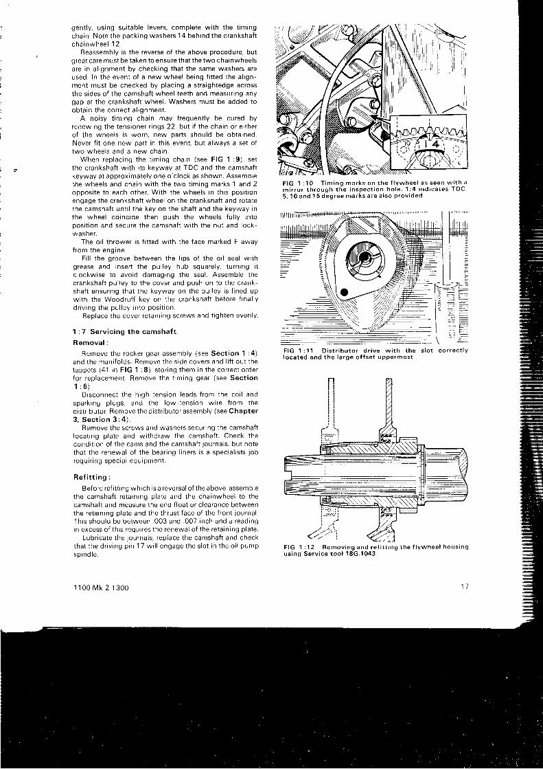
F I G 1 : 1 0 T i m i n g m a r k s o n t h e f l y w h e e l a s s e e n w i t h am i r r o r t h r o u g h t h e i n s p e c t i o n h o l e . 1 1 4 i n d i c a t e s T D C5 , 1 0 a n d 1 5 d e g r e e m a r k s a r e a i s o p r o v i d e d
F I G 1 : 1 1 D i s t r i b u t o r d r i v e w i t h t h e s l o t c o r r e c t l yloca ted and the la rge o f fse t uppermost
1 1
F I G 1 : 1 2 R e m o v i n g a n d r e f i t t i n g t h e f l y w h e e l h o u s i n gu s i n g S e r v i c e t o o l 1 8 G . 1 0 4 3
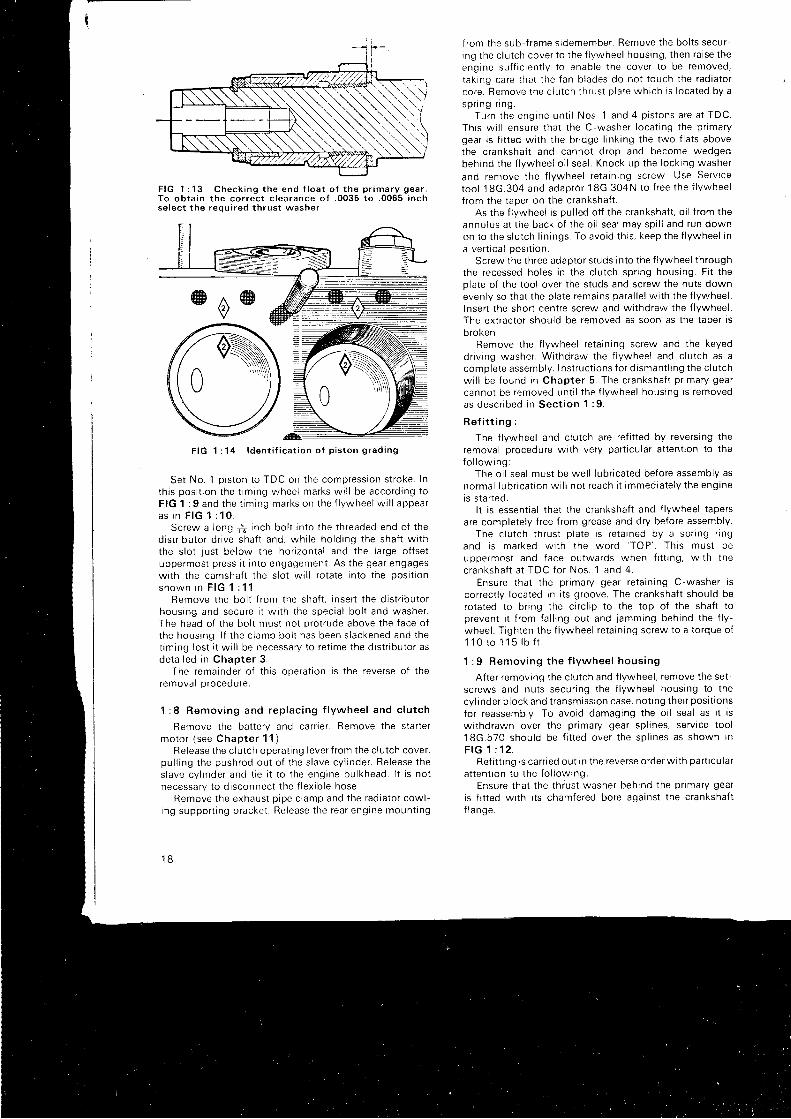
F I G 1 : 1 3 C h e c k i n g t h e e n d f l o a t o f t h e p r i m a r y g e a r .T o o b t a i n t h e c o r r e c t c l e a r a n c e o f . 0 0 3 5 t o . 0 0 6 5 i n c hs e l e c t t h e r e o u i r e d t h r u s t w a s h e r
Set No. 1 p iston to TDC on the compression stroke. Int h i s pos i t i on t he t im ing whee l ma rks w i l l be acco rd i ng t oF IG 1 : 9 and t he t im ing marks on t he f l ywhee l w i l l appea ra s i n F I G 1 : 1 O .
Screw a Iong 1f inch bol t into the threaded end of thed i s t r i bu to r d r i ve sha f t and , wh i l e ho ld i ng t he sha f t w i t hthe s lot just below the hor izontal and the large of fsetuppermost press i t in to engagement. As the gear engageswith the camshaft the s lot wi l l rotate into the posi t ion
s h o w n i n F I G 1 : 1 1 .Remove the bol t f rom the shaf t , insert the dist r ibutor
hous ing and secu re i t w i t h t he spec ia l bo l t and washe r .The head of the bol t must not protrude above the face ofthe housing. l f the c lamp bol t has been s lackened and thet tming lost i t wi l l be necessary to ret ime the dist r ibutor asde ta i l ed i n chap te r 3 .
The remainder of th is operat ion ts the reverse of theremovar proceoure.
1 : 8 Remov ing and rep lac i ng f l ywhee l and c l u t ch
Remove the bat tery and carr ier . Remove the star termo to r ( see Chap te r 1 1 ) .
Release the c lutch operat ing lever f rom the c lutch cover,pu l l i ng t he push rod ou t o f t he s l ave cy l i nde r . Be lease t hes lave cy l i nde r and t i e i t t o t he eng ine bu l khead . l t i s no tnecessa ry t o d i sconnec t t he f l ex i b l e hose .
Remove t he exhaus t p i pe c l amp and t he rad ia to r cow l -i ng suppo r t i ng b racke t . Re lease t he rea r eng tne moun t t ng
1 B
f rom the sub-f rame sidemember. Remove the bol ts secur-ing the c lutch cover to the f lywheel housing. then ra ise theeng ine su f f r c i en t l y t o enab le t he cove r t o be removed ,
taking care that the fan blades do not touch the radiatorco re . Remove t he c l u t ch t h rus t p l a te wh i ch i s l oca ted by aspnng i l ng .
Tu rn t he eng ine un t i l Nos . 1 and 4 p i s t ons a re a t TDC.Th i s w i l l ensu re t ha t t he C -washe r l oca t i ng t he p r ima rygear ls f i t ted wi th the br idge l ink ing the two f lats abovethe crankshaft and cannot drop and become wedgedbeh ind t he f l ywhee l o i i sea l . Knock up t he l ock i ng washe r
and remove t he f l ywhee l r e ta i n i ng sc rew Use Se rv i ce
too l 18G.304 and adap to r 18G.304N to f r ee t he f l ywhee l
f r om the t ape r on t he c ranksha f t .As the f lywheel is pul led ot f the crankshaft , o i l f rom the
annu lus a t t he back o f t he o i l sea l may sp i l l and run downon to the s lutch l in ings. To avoid thrs, keep the f lywheel ina vert ical oosi t ion.
Screw the three adaptor studs into the f lywheel throughthe recessed holes in the c lutch spr ing housing. Fi t theolate of the tool over the studs and screw the nuts downevenly so that the plate remains paral le l wi th the f lywheel .Insert the short centre screw and wi thdraw the f lywheel .The extractor shoulc i be removed as soon as the taper isb roken .
Remove the f lywheel reta in ing screw and the keyeddrrv ing washer. Withdraw the f lywheel and c lutch as acomp le te assemb ly . I ns t r uc t i ons f o r d i sman t l i ng t he c l u t chw i l l be f ound i n Chap te r 5 . The c ranksha f t p r ima ry gea rcannot be removed unt i l the f lywheel housing is removedas desc r i bed i n Sec t i on 1 : 9 .
R e f i t t i n g :
The f lywheel and c lutch are ref i t ted by revers ing theremoval procedure wi th very part icular at tent ion to thefo l l ow ing :
The oi l seal must be wel l lubr icated before assembly asno rma l l ub r i ca t i on w i l l no t r each i t immed ia te l y t he eng lneis star ted.
I t is essent ia l that the crankshaft and f lywheel tapersare completely f ree f rom grease and dry before assembly.
The c l u t ch t h rus t p l a te i s r e ta i ned by a sp r i ng r i ngand i s ma rked w i t h t he wo rd
' TOP ' . Th i s mus t be
uppe rmos t and f ace ou twa rds when f i t t r ng , w i t h t hec ranksha f t a t TDC fo r Nos . 1 and 4 .
Ensure that the pr imary gear reta in ing C-washer iscorrect ly located in i ts groove. The crankshaft should berotated to br ing the c i rc l ip to the top of the shaf t top reven t i t i r om fa l l r ng ou t and j amming beh ind t he f l y -wheel . T ighten the f lywheel reta in ing screw to a torque of1 1 0 r o 1 1 5 l b f t .
1 : 9 Remov ing t he f l ywhee l hous ing
After removing the c lutch and f lywheel , remove the set-screws and nuts secur ing the f lywheel housing to thecyl inder b lock and t ransmission case, not ing their posi t ions
for reassembly. To avoid damaging the oi l seal as i t iswi thdrawn over the pr imary gear splrnes, serv ice tool18G.570 shou ld be f i t t ed ove r t he sp l i nes as shown i nF I G 1 : 1 2 .
Ref i t t ing is carr ied out in the reverse order wi th part icular
a t t en t i on t o t he f o l l ow ing :Ensure that the thrust washer behind the pr imary gear
is f i t ted wi th i ts chamfered bore against the crankshaftf l anqe .
F I G 1 : 1 4 l d e n t i f i c a t i o n o f p i s t o n g r a d i n g
Check t he end f l oa t o f t he p r ima ry gea r and ad jus t i t byse lec t i ve assemb ly o f t he t h rus t washe r as i nd i ca ted byF I G 1 : 1 3 .
C lean t ho rough l y a l l ma t i ng f aces and f i t a new BMCgaske t .
Renew any o i l sea l s wh i ch show the s l i gh tes t s i gns o fdamage o r l eakage .
Pack t he bea r i ng ro l l e r s o f t he f i r s t mo t i on sha f t w i t hh igh me l t i ng po in t g rease t o p reven t t hem t i l t r ng as t hehous ing i s r e f i t t ed . Use t oo l 18G.570 ove r t he p r ima ry gea rspl ines as before and screw the two pi lot bars which arepart of th is tool set into the two bot tom tapped holes int he c rankcase . These w i l l gu i de t he hous ing i n t o p l ace andalso take the weight of f the seal . l t at is necessary to renewthe gea r t r a i n t he t r ansm iss i on cas ing mus t be removed t oenab le t he i d l e r gea r end f l oa t t o be measu red ( see
Sec t i on 1 : ' l 0 ) .Ensure that the correct short setscrew is f r t ted at the
r i gh thand t op pos i t i on i n t he hous ing as a l ong sc rewmigh t damage t he o i l ga l l e r y i n t he cy l i nde r b l ock .
T igh ten t he hous ing bo l t s and nu t s t o a t o rque o f 18lb f t wh i ch w i l l g i ve t he gaske t a compress ion t h i ckness o f. 030 i nch . The re i s a sma l l cu i away i n t he gaske t t o pe rmr tt he i nse r t i on o f a f ee le r gauge t o check t h i s measu remen t
1 : 10 Remov ing t he synch romesh t r ansm iss i on
Remove t he eng ine , f l ywhee l and c l u t ch , s t a r t e r mo to rand f l ywhee l hous ing as a l r eady desc r i bed , t hen w r thd rawthe se t sc rews f r om the f l ange o f t he t r ansm iss i on caseUs ing su i t ab le t ack l e l i f t t he eng rne t o sepa ra te i t f r om thet ransmtss ton case .
l ns t r uc t i ons {o r d i sman t l i ng t he t r ansm iss ron a re g i venin Chap te r 6 . Re f i t as f o l i ows :
Tho rough l y c l ean a l l l o i n t f aces Check t he end f l oa t o fthe id ler gear, i f new gears have been f i t ted, before the casei s r ep laced ( see Chap te r 6 ) .
T i gh ten a l l secu r i ng nu t s and bo l t s f i nge r t i gh t a t f r r s t ,t hen one t u rn a t a t ime t o ensu re an even p ressu re a l lr ound . Th i s w i l l no t on l y p roduce un o ,11 ;gh t Jo i n t bu t a l sokeep t he gea rs i n co r rec t r e l a t i onsh ip
See t ha t t he f r on t bea r i ng co rk o i l sea l r ema ins co r rec t l ypos i t i oned du r i ng t hese ope ra t i ons
1 : 1 1 S e r v i c i n g t h e c r a n k s h a f t p r ! m a r y g e a r
Th i s gea r i s r emoved a f t e r t he f l ywhee l hous ing hasbeen removed as desc r i bed i n Sec t i on 1 : 9 by ex t r ac t i ngthe re ta i n i ng C -washe r and t he back ing washe r , t henw i t hd raw ing t he gea r t oge the r w i t h t he t h rus t washe rs . l tw i l l be no ted t ha t non - l ub r i ca ted bushes a re f i t t ed t o t heseeng ines t o e l im rna te t he l eakage o f o i l i n t o t he c l u t ch .
When ref i t t ing the gear measure the end f loat betweenthe i nne r t h rus t washe r and t he gea r i t se l f , and , by aselect ion of v ' rashers as indicated in the table below. obtarnthe co r rec t r unn ing c l ea rance o f be tween . 0035 and 0065inch . Th i s i s i l l u s t r a ted i n F IG 1 : 13 .
When the gap is. 1 1 7 5 t o 1 1 9 i n c h
. 1 1 9 t o . 1 2 1 i n c h
.121 ro .123 inctr
. 1 2 3 t o 1 2 5 i n c h
1 1 00 Mk 2 1 300
Use washer thickness. 1 1 2 t o . 1 1 4 i n c h. 1 1 4 1 o . 1 1 6 i n c h. 1 1 6 t o . 1 1 8 i n c h. 1 1 8 t o . 1 2 0 i n c h
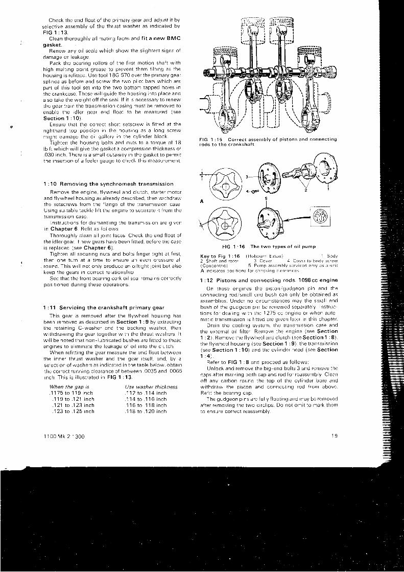
F I G 1 : 1 5 C o r r e c t a s s e m b l y o f p i s t o n s a n d c o n n e c t i n gr o d s t o t h e c r a n k s h a f t
+€\,--n(/z+s\r r*J,)\YZl o-s-\l/
a \-Y--l ?
F I G 1 : 1 6 T h e t w o t y p e s o f o i l p u m p
K e y t o F i g 1 : 1 6 ( H o b o u r n E a t o n ) 1 B o d y2 Shaf t and ro to r 3 Cover 4 Cover to bodv screw( C o n c e n t r i c ) 5 P u m p a s s e m b l y s e r v i c e d o n l y a s a u n r tA i nd rca tes pos r t r ons f o r check ing c l ea rances
1 : 12 P i s t ons and connec t i ng rods . 1098cc eng ine
On these eng rnes t he p i s t on /gudgeon p i n and t heconnec t i ng rod rsma l l end bush can on l y be cb ta i ned asassemb l i es . Unde r no c i r cums tances may t he sma l l endbush o f t he gudgeon p rn be renewed sepa ra te l y . I ns t r uc -t i ons f o r dea l i ng w i t h r he 1215 cc eng ine o r when au to -ma t i c t r ansm iss i on i s f i t t ed a re g i ven l a t e r i n t h i s chap te r .
D ra i n t he coo l i ng sys tem, t he l r ansm iss i on case andthe ex te rna l o i l f i l t e r . Remove t he eng ine ( see Sec t i on1 : 2 ) . Remove t he f l ywhee l and c l u t ch ( see Sec t i on 1 : 8 ) ,t he f l ywhee l hous ing ( see Sec t i on 1 : 9 ) , t he t r ansm iss i on(see Sec t i on 1 : 10 ) and t he cy i i nde r head ( see Sec t i on1 : 4 ) .
Re fe r t o F IG 1 : 8 and p roceed as f o l l ows :Un lock and remove t he b i g -end bo l t s 3 and remove t he
caps a f t e r ma rk i ng bo th cap and rod f o r r eassemb ly . C leano f f any ca rbon round t he t op o f t he cy l i nde r bo re andw i t hd raw the p r s ton and connec t i ng rod f r om aboveRe f i t t he bea r rng cap .
The gudgeon p i ns a re f u l l y f l oa t i ng and may be removeda f t e r r emov ing t he two c i r c l i p s . Do no t om i t t o ma rk t hemto ensu re co r rec t r eassemb ly .
1 9

N ' , /
F I G 1 : 1 7 C r a n k c a s e e m i s s i o n c o n t r o l s y s t e m
1 Oi l separa tor 2 Breather hose 3 Carbure t te r chamber connect ion 4 F i l le red f i l l e r capK e y t o F i g 1 : 1 7
Ref i t t ing is the reverse of the above, taking care that a l lparts are replaced in their or ig inal posi t ions and that theprston rrng gaps are at 90 deg. to each other.
P i s t on r i ngs :
These should always be removed over the top of thepiston and are convenient ly l i f ted out of their grooves byinsert ing a broken hack-saw blade or d isused feeler gaugeunde r one end o f t he r i ng and pass ing i t a round t he r i ngto ease i t upwards. Very careful ly c lean out any carbondeposi ts f rom the piston r ing grooves.
Before f i t t ing new r ings the cyl inder bore glaze shouldbe removed, preferably wi th equipment designed for thepurpose, but i f necessary wi th a dummy wooden pistonwith very f ine glasspaper wrapped around i t .
Checking the correct p iston r ing gap may be done byinsert ing a piston about one inch down the bore and
20
pushing the r ing down on top of i t to keep i t square to thebore. The gap between the two ends mav then be measuredw i t h a f ee le r gauge . t n r s shou ld be . u06 t o . 01 1 i nch andthe ends may be f i led out i f necessary.
The second and th i rd r ings are tapered and must bef i t ted wi th the narrow taper upwards. This top face rsstamped wi th the let ter T.
P i s t on s i zes :
I t wi l l be seen that each oiston is marked on the crownw i t h a number enc losed i n a d i amond . Th i s i nd i ca tes i t ss ize grading and each piston should be f i t ted to a bore ofs imr lar s ize as stamped on the block adjacent to the bore( s e e F I G 1 : 1 4 ) .
Two oversize pistons are avai lable, +.0 '1 0 and +.020inch and the pistons crowns are stamped wi th the actualovers ize dimension in an el ipse. A piston stamped .020 issui table only for a bore .020 inch larger than standard and
neeono
b€r s
simi lar ly for other markings. When f i t t ing overs ize prstonsalways see that the block is stamDed wi th the overs ize.
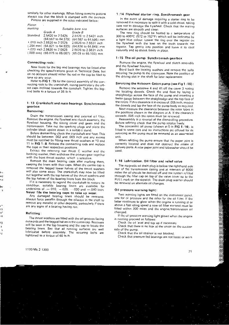
Pistons are suppl ied in the s izes indicated below:
Pistonmarking Suitable bore size
Grade BGrade A
1 : 14 F l ywhee l s t a r t e r r i ng . Synch romesh gea r
In the event of damage requir ing a star ter r ing to beremoved i t is necessary to spl i t i t wi th a cold chisel , tak ingcare not to damage the f lywheel . Check that the mat ingsurfaces are smooth and c lean.
The new r ing should be heated to a temDerature of300 t o 400oC (572 to 752 .F ) wh i ch w i l l be i nd i ca ted bya l ight b lue colour. Lower the r ing over the register onthe f lywheel wi th the lead on the teeth towards theregrster . Tap gent ly rnto posi t ion and leave i t to coolna tu ra l l y and so sh r i nk f i rm l v i n p l ace .
1 : 15 The o i l pump . Synch romesh gea rbox
Remove the engine. the f lywheel and c lutch assemblvand the f lywheel housing.
Bend back the locking washers and remove the botrssecur ing the pump to the crankcase. Note the posi t ion ofthe dr iv ing s lot in the shaf t for later replacement.
Se rv i c i ng t he Hobou rn -Ea ton pump ( see F ig 1 : 16 ) :
Remove the setscrew 4 and l i f t of f the cover 3 not ingthe locat ing dowels. Check the end f loat by lay ing astra ightedge across the face of the pump and insert ing afeeler gauge between the stra ightedge and the top face ofthe rotors. l f th is c learance is in excess of .005 inch, removethe dowels and lap the face of the pump body as required.
Next measure the c learance between the rotor lobes rnthe posrt ions shown in the diagram at A. l f the c learanceexceeds .006 inch the rotors must be renewed.
Reassembly is a reversal of the dismant l ing procedure.Before ref i t t ing check that the pump rotates f reely.
The concen t r i c o i l pump ( shown a t 5 i n F IG 1 :16 ) , i sf i t ted to some cars and no instruct ions are of fered for i tsserv ic ing as the pump must be renewed as an assembledun i t .
When ref i t t ing the pump ensure that the paper jo int iscorrect ly located and does not obstruct the intake ofdel ivery ports. A new paper lo int and tabwasher shoulo oeused.
1 : 16 Lub r i ca t i on . O i l f i l t e r and re l i e f va l ve
The magnet ic o i l drain p lug is below the r ighthand s iderear of the t ransmission casing and at intervals of 6000mi les the oi l should be drained of f and the system ref i l ledthrough the f i l ler cap on top of the valve cover uo to tneFULL mark on t he d i ps t i c k . The d ra i n p l ug washe r shou ldbe renewed on al ternate oi l changes.
O i l p ressu re wa rn ing l i gh t :
Two warning l ights are f i t ted on the instrument panel ,one for o i l pressure and the other for the oi l f i l ter . l f thelat ter cont inues to g low when the engine is running at orabove a fast id l ing speed a new oi l f i l ter e lement must bef i t ted wi th in 300 mi les and the engine/ t ransmission orrchanged .
l f the oi l pressure warning l ight g lows when the engineis running proceed as fo l lows:
Check the oi l level and top up i f necessary.Check that there is no leak at the union on the suct ion
s ide o f t he pump .Check that the oi l s t ra iner is not b locked.Check that pressure fed bear ings are not loose or worn
Standard 2.5420 to 2.5425 2.5426 to 2 b431 incn(64.567 to 64.579) (64.582 to 64.b9b) mm
+ .01 0 inch 2.5520 to 2.5525 2.5526 ro 2.5531 in c h( . 254 mm) (64 .821 ro 64 .833 ) ( 64 .836 t o 64 .849 ) r nm+.020 inch 2.5620 to 25625 2.5626 ro 2 b631 inch( . 508 mm) (65 .075 t o 65 087 ) ( 6b 09 t o 65 .103 ) mm
Connec t i ng rods :
New l iners for the big-end bear ings may be f i t ted af tercheckrng the speci f icat ions given in Technical Data, bulon no accoont should ei ther the rod or the cap be f i leo rotake up any wea r .
Refer to FIG 1 :15 for the correct assembly of the con_nect ing rods to the crankshaft , not ing part icular ly the of f_set caps incl ined towards the camshaft . T ighten the big_end bol ts to a lorque of 35 lb f t .
1 : 13 C ranksha f t and ma in bea r i ngs . Synch romeshgearbox
R e m o v i n g :
Drain the t ransmission casing and external o i l f i l ter .Remove the engine, the f lywheel and c lutch assemblv. rnef lywheel housing, the t iming cover and gears and thetransmission. Take out the sparking plugs and place thecyl inder b lock upside down in a sui table stand.
Before dismant l ing check the crankshaft end f loat . Thisshould be between .002 and .003 inch and any excessmust be rect i f ied by f i t t ing new thrust washers at 1O ano11 in FIG 1 :8. Release the connect ing rods and replacethe caps in their respect ive posi t ions.
Ex t rac t t he re ta i n tng rea r t h rus t C washe r and t neback ing washe r , t hen w i t hd raw the p r ima ry gea r t oge tne rwath the f ront thrust washer, which is select ive.
Remove the main bear ing caps af ter marking them,keeping the l iners wi th their caps. When the centre cap isremoved the tagged lower halves of the thrust washerswi l l a lso come away. The crankshaft may now be l i t tedout together wi th the top halves of the thrust washers andthe top halves of the bear ing l iners f rom the block.
l f i t is necessary to regr ind the crankshaft to restore t tscondi t ion, sui table bear ing l iners are avai lable forunde rs i zes o f . - 010 , - . 02O , - . 030 and _ .040 i nch .Never f i le the bear ing caps to take up wear.
Any damaged bear ing l iners should be renewed.Always force paraf f in through the oi lways in the shaf i roremove any metal l ic or other deposi ts, part icular ly i f thereare any s igns of a bear ing having run.
Re f i t t i ng :
The thrust washers are f i t ted wi th the oi l grooves facingoutwards and the tagged halves in the centre cap. Recesseswi l l be seen in the top housing and the cap to locate thebear ing l iners. See that a l l running surfaces are wel llubr icated before assembly. The secur ing bol ts aret ightened to a torque of 60 lb f t .
1 100 Mk 2 1300z l
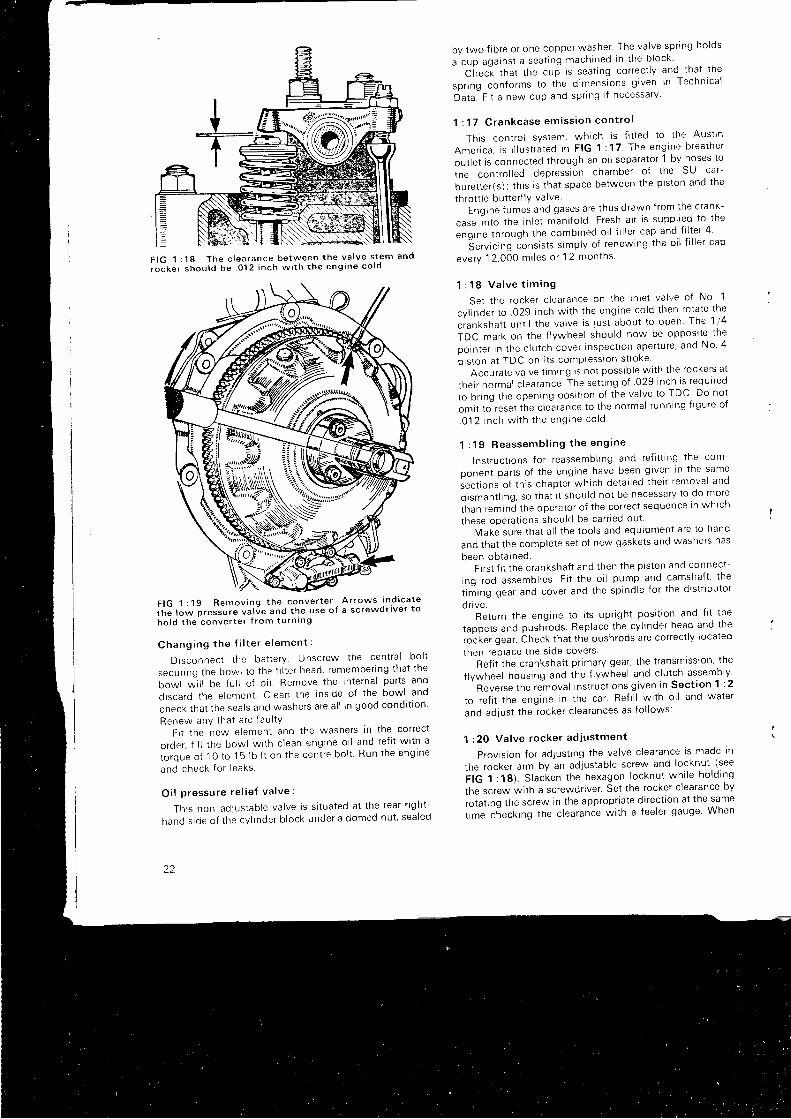
F I G 1 : 1 8 T h e c l e a r a n c e b e t w e e n t h e v a l v e s t e m a n d
i o c k e r s h o u l d b e o 1 2 i n c h w i t h t h e e n g i n e c o l d
F IG 1 : 19 Remov ing t he conve r t e r ' A r rows i n . d i ca te
i t r " r " * p r " r r u t " va l Je and t he use o f a sc rewd r i ve r t o
ho ld t he conve r t e r f r om tu rn i ng
C h a n g i n g t h e f i l t e r e l e m e n t :
D i sconnec t t he ba t t e r y . Unsc rew the cen t ra l bo l t
secu r i ng t he bow l t o t he f l l t e r head , r emember i ng t ha t t he
bo*t *" i t t be fu l l of o i l Remove the internal parts and
d i sca rd t he e l emen t . C lean t he i ns i de o f t he bow l and
check t ha t t he sea l s and washe rs a re a l l i n good cond i t i on
Renew any t ha t a re f au l tY
F i t t he new e lemen t and t he washe rs i n t he co r rec t
o rde r , f i l l t he bow l w i t h c l ean eng ine o i l and re f i t w i t h a
L rque o f 10 t o 15 l b f t on t he cen t re bo l t Run t he eng ine
and check f o r l eaks
O i l p ressu re re l i e f va l ve :
Th rs non ad lus tab le va l ve i s s i t ua ted a t t he rea r r i gh t -
hand s i de o f t he cv l i nde r b l ock unde r a domed nu t ' sea led
22
by two f i b re o r one coppe r washe r ' The va l ve sp r i ng ho lds
a cup aga ins t a sea t i ng mach ined i n t he b l ock '- Ci- rec"t that the cup is seat ing correct ly and that the
sp r i ng con fo rms t o t he d imens ions g i ven i n Techn l ca l
Da ta . F i t a new cup and sp r i ng i f necessa ry
1 : 1 7 C r a n k c a s e e m i s s i o n c o n t r o l
Thrs contro l system, which is f i t ted to the Aust in
Amer i ca , i s i l l u s t r a ted i n F IG 1 : 17 The eng ine b rea the r
out let is connected through an oi l separator 1 by hoses to
rhe contro l led depression chamber of the SU car-
buret ter(s) ; th is is that space between the piston and the
throt t le but ter f lY valvei ng ine f umes and gases a re t hus d rawn f r om the c rank -
case i n t o t he i n l e t man i f o l d . F resh a i r i s supp l i ed t o t he
eng ine t h rough t he comb ined o i l f i l l e r cap and f i l t e r 4
6e rv i c i ng Jons i s t s s imp l y o f r enew ing t he o i l f i l l e r cap
eve ry 12 ,000 m i l es o r 12 mon ths
1 : 1 8 V a l v e t i m i n g
Se t t he rocke r c l ea rance on t he i n l e t va l ve o f No 1
cy l i nde r t o . 029 i nch w i t h t he eng ine co ld t hen ro ta te t he
c ianksha f t un t i l t he va l ve i s j us t abou t t o open f he 1 l 4
TDC mark on t he f l vwhee l shou ld now be oppos l t e I ne
po in te r i n t he c l u t ch cove r i nspec t i on ape r t u re ' and No 4
piston at TDC on i ts compresston strore
Accu ra te va l ve t im rng i s no t poss ib l e w i t h t he rocke rs a t
t he i r no rma l c l ea rance . The se t t i ng o f 029 i nch i s r equ r red
to b r i ng t he open ing pos i t i on o f t he va l ve t o TDC Do no t
om i t t o " rese t t he c l ea rance t o t he no rma l r unn ing f i gu re o f
. 0 1 2 i n c h w i t h t h e e n g i n e c o l d '
1 : 1 9 R e a s s e m b l i n g t h e e n g i n e
Ins t r uc t i ons f o r r eassemb l i ng and re f i t t i ng t he com-
ponen t pa r t s o f t he eng ine have been g i ven I n t he same
sec t i ons o f t h r s chap te r wh i ch de ta i l ed t he i r r emova l and
d i sman t l i ng , so t ha t i t shou ld no t be necessa ry l o do more
than rem ind t he ope ra to r o f t he co r rec t sequence I n wn l cn
these operat ions should be carr led out
Make su re t ha t a l l t he t oo l s and equ ipmen t a re t o hand
and that the complete set of new gaskets and washers has
been ob ta i ned .F i r s t f i t t he c ranksha f t and t hen t he p i s t on and connec t -
i ng rod assemb l i es . F i t t he o i l pump and camsha f t ' t he
t i r i i ng gea r and cove r and t he sp ind le f o r t he d i s t r i bu to r
d r i ve .Return the engine to i ts upr ight posi t ion and f i t the
tappe t s and push rods Rep lace t he cy l i nde r head and t ne
,o. i . " , g"ut . bheck that the pushrods are correct ly located
then reP lace t ne s l de cove rs '
Ref i t the crankshaft pr imary gear, the t ransmlsslon' tne
f lywheel housing and the f lywheel and c lutch assembly '
Reve rse t he remova l I ns t r uc t i ons g i ven i n sec t i on 1 : 2
to r e f i t t he eng ine i n t he ca r . Re f i l l w i t h o i l and wa te r
and ad jus t t he rocke r c l ea rances as f o l l ows :
1 : 20 Va l ve rocke r ad jus tmen t
P rov i s i on f o r ad lus t i ng t he va l ve c l ea rance i s made t n
the rocker arm by an adjustable screw and locknut (see
i tC t , t g ) S lacken t he hexagon l ocknu t wh i l e ho ld i ng
the screw wi th a screwdr iver ' Set the rocker c learance by
rotat ing the screw in the appropr iate d i rect lon at the same
t 'me c teck i ng t he c l ea rance w i t h a f ee le r gauge When
the correct gap has been obtained ret ighten the locknutaga in ho ld i ng t he sc rew aga ins t r o ta t i on .
In order to ensure the correct posi t ion of the tappet oni ts cam at the t ime of adjustment the fo l lowing table wi l lbe he lp fu l :
Ad jus t No . 1 r ocke r w r t h No . 8 va l ve f u l l y openAd jus t No . 3 r ocke r w i t h No . 6 va l ve f u l l y openAd jus t No . 5 r ocke r w i t h No . 4 va l ve f u l l y openAd jus t No . 2 r ocke r w i t h No . 7 va l ve f u l l y openAd lus t No . 8 r ocke r w i t h No . 1 va l ve f u l l y openAd jus t No . 6 r ocke r w i t h No . 3 va l ve f u l l y openAd jus t No . 4 r ocke r w i t h No . 5 va l ve f u l l y openAd jus t No . 7 r ocke r w i t h No . 2 va l ve f u l l y openTo avoid constant reference to the table i t wi l l be noted
tha t t he numbers i n each l i ne add up t o n i ne .A f t e r r unn ing t he eng ine f o r a f ew m i l es i t w i l l be
necessary to t ighten down the cyl inder head and to resett he va l ve c l ea rances .
1 :21 Ope ra t i ons a f f ec ted by au toma t i c t r ans -m iss i on
In th is sect ion instruct ions wi l l be given for carry ingout operat ions al ready descr ibed for engines wi th synchro-mesh t ransmission i f the f i t t ing of automat ic t ransmissionmakes a change in procedure necessary.
Va l ve t im ing :
Th i s i s ca r r i ed ou t as i n Sec t i on 1 :18 bu t t he c rank -shaf t is rotated by insert ing a screwdr iver through the holein the converter housing and on to the converter star terr ing gear unt i l the 1 4 TDC mark on the converter isopposi te the pointer on the cover.
Se rv i c i ng t he camsha f t .
Extreme care is necessary when removing the camshaft .The oi l pump dr ive coupl ing may st ick by oi l adhesion tothe camshaft and oossib lv fa l l in to the t ransmission uni t .Ensu re t ha t t h i s d r i ve coup l i ng i s f u l l y l oca ted on t hesp l i ned o i l pump sp ind le when re f i t t i ng t he camsha f t .
l f i t is found necessary to renew the camshaft bear ingsthe converter and t ransmission uni t must be removed asfo l l ows :
Remov ing t he t r ansm iss i on un i t :
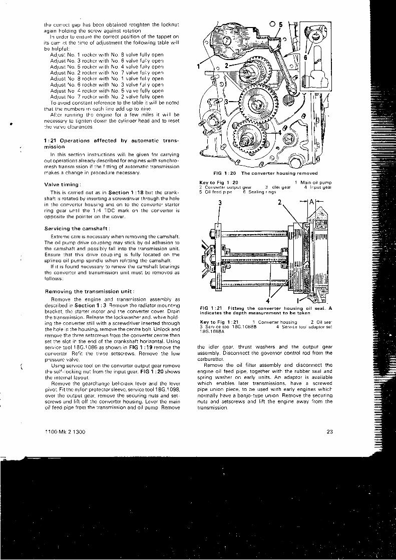
Remove the engine and t ransmission assembly asdesc r i bed i n Sec t i on 1 : 3 . Remove t he rad ia to r moun t i ngbracket . the star ter motor and the converter cover. Drainthe t r ansm iss i on . Re lease t he l ockwashe r and , wh i l e ho ld -ing the converter st i l l wi th a screwdr iver inserted throughthe hole in the housing, remove the centre bol t . Unlock andremove the three setscrews f rom the converter centre thenset the s lot in the end of the crankshaft hor izontal . Usingse rv i ce t oo l 18G.1086 as shown i n F IG 1 : 19 remove t heconverter . Ref i t the three setscrews. Remove the loworessure valve.
Using serv ice tool on the converter output gear removethe se l f - l ock i ng nu t f r om the i npu t gea r . F IG 1 : 20 showsthe internal layout .
Remove the gearchange bel lcrank lever and the leverpivot . F i t the nylon protectors leeve, serv ice tool 1 8G. '1 098,over the output gear, remove the secur ing nuts and set-screws and l i f t of f the converter housing. Lever the mainoi l feed pipe f rom the t ransmission and oi l pump. Remove
1 1 00 Mk 2 1 300
FIG 1 :20 The conver te r hous ing removed
K e y t o F i g 1 : 2 0 ' 1 M a i n o i l p u m p
2 Conver te r ou tpu t gear 3 ld le r gear 4 lnput gear5 O r l f e e d p i p e 6 S e a l i n g r i n g s
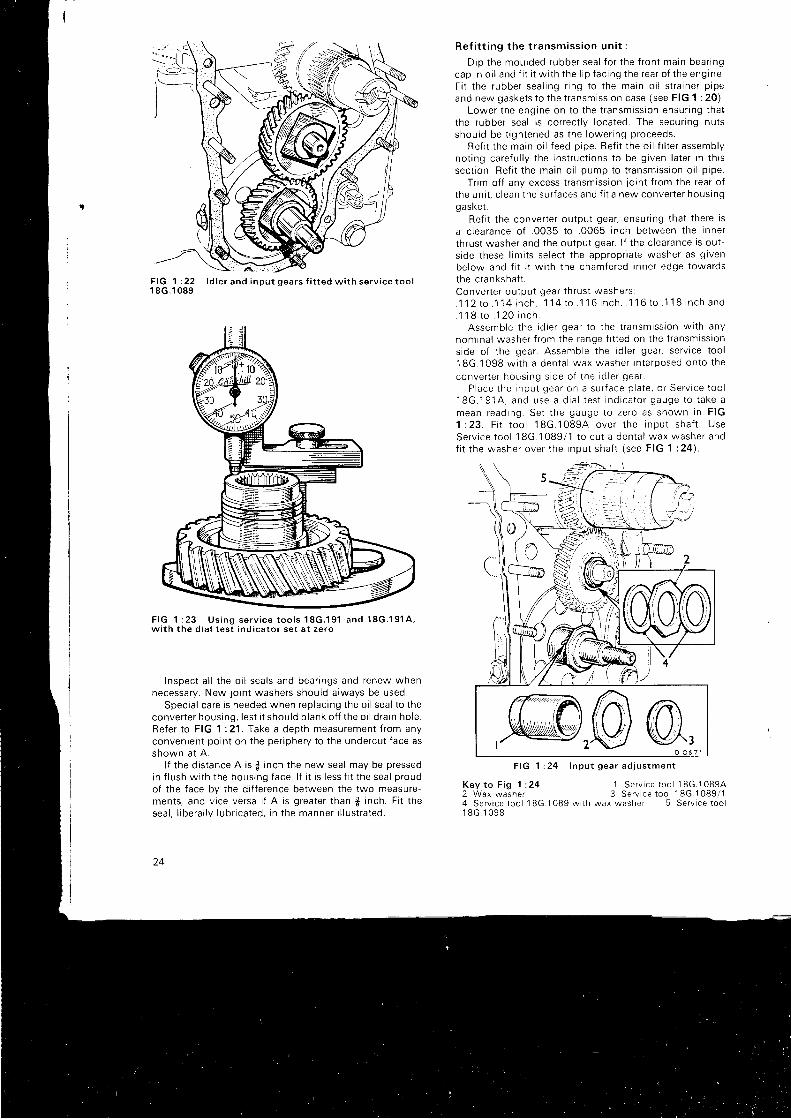
F I G 1 : 2 1 F i t t i n g t h e c o n v e r t e r h o u s i n g o i l s e a l . Aind ica tes the depth measurement to be taken
Key to F ig 1 :21 '1 Conver te r hous ing 2 O i l sea l
3 Serv ice too l 18G. '1 0688 4 Serv ice too l adaotor se t' 1 8 G . 1 0 6 8 A
the id le r gear , th rus t washers and the ou tpu t gear
assembly. Disconnect the governor contro l rod f rom thecarbu ret ter .
Remove the oi l f i l ter assembly and disconnect theeng ine o i l f eed p i pe , t oge the r w i t h t he rubbe r sea l andsp r i ng washe r on ea r l y un i t s . An adap to r i s ava i l ab l ewhrch enables later t ransmissions, have a screwedp ipe un ion p i ece , t o be used w i t h ea r l y eng ines wh i chnormal ly have a banjo- type union. Remove the secur ingnuts and setscrews and l i f t the engine away f rom thet ransmtss ron .
23
F I G 1 : 2 21 8G.1 089
F IG 1 : 23 Us ing se rv i ce t oo l s 1 8G .1 91 and 18G.1 91 A ,w i t h t he d i a l t es t i nd i ca to r se t a t ze ro
Inspec t a l l t he o i l sea l s and bea r i ngs and renew whennecessary. New jo int washers should always be used.
Spec ia l ca re i s needed when rep lac i ng t he o i l sea l t o t heconve r t e r hous ing , l es t i t shou ld b l ank o f f t he o i l d ra i n ho le .Re fe r t o F IG 1 :21 . Take a dep th measu remen t f r om anyconvenient point on the per iphery to the undercut face asshown a t A .
l f the distance A is $ inch the new seal may be pressedin f lush wi th the housing face. l f i t is less f i t the seal proudof the face by the di f ference between the two measure-ments, and v ice versa i f A is greater than 3 inch. Fi t thesea l , l i be ra l l y l ub r i ca ted , i n t he manne r i l l u s t r a ted .
24
Ref i t t i ng t he t r ansm iss i on un i t :
D ip t he mou lded rubbe r sea l f o r t he f r on t ma in bea r i ngcap i n o i l and f i t i t w i t h t he l i p f ac i ng t he rea r o f t he eng ine .F i t t he rubbe r sea l i ng r i ng t o t he ma in o i l s t r a i ne r p i peand new gaske t s t o t he t r ansm iss i on case ( see F IG 1 : 20 ) .
Lower t he eng ine on t o t he t r ansm iss i on ensu r i ng t ha tthe rubber seal is correct ly located. The secur ing nutsshou ld be t i gh tened as t he l owe r i ng p roceeds .
Re f i t t he ma in o i l f eed p i pe . Re f i t t he o i l f i l t e r assemb lyno t i ng ca re fu l l y t he i ns t r uc t i ons t o be g i ven l a t e r i n t h i ssec t i on . Re f i t t he ma in o i l pump to t r ansm iss i on o i l p i pe .
Tr im of f any excess t ransmission lo int f rom the rear oft he un i t , c l ean t he su r f aces and f i t a new conve r t e r hous inggaske t .
Re f i t t he conve r t e r ou tpu t gea r , ensu r i ng t ha t t he re i s
a c l ea rance o f . 0035 t o . 0065 i nch be tween t he i nne r
t h rus t washe r and t he ou tpu t gea r . l f t he c l ea rance i s ou t -s i de t hese l im i t s se l ec t t he app rop r i a te washe r as g i ven
be low and f i t i t w i t h t he chamfe red i nne r edge t owa rdsthe c ranksha f t .Conve r t e r ou tpu t gea r t h rus t washe rs :. 1 1 2 r o . 1 1 4 i n c h , 1 1 4 t o 1 1 6 i n c h , 1 1 6 t o . 1 1 8 i n c h a n d1 1 8 t o . 1 2 0 i n c h .
Assemb le t he i d l e r gea r t o t he t r ansm iss ton w i t h anynom ina l washe r f r om the range f i t t ed on t he t r ansm iss i ons ide o f t he gea r . Assemb le t he i d l e r gea r , se r v i ce t oo l18G.1098 w i t h a den ta l wax washe r i n t e rposed on to t he
conve r t e r hous ing s i de o f t he i d l e r gea r .P lace t he i npu t gea r on a su r f ace p l a te , o r Se rv i ce t oo l
1 8 G . 1 9 1 A , a n d u s e a d i a l t e s t i n d i c a t o r g a u g e t o t a k e amean read rng . Se t t he gauge t o ze ro as shown i n F IG1 : 2 3 . F i t t o o l 1 8 G . 1 0 8 9 4 o v e r t h e i n p u t s h a f t . U s eSe rv i ce t oo l 18G.1089 /1 t o cu t a den ta l wax washe r andf i t t he washe r ove r t he i npu t sha f t ( see F IG 1 : 24 ) .
Key t o F i g 1 : 242 Wax washe r
1 S e r v i c e t o o l ' 1
8 G . 1 0 8 9 43 S e r v i c e t o o l 1 8 G . 1 0 8 9 / 1
4 S e r v i c e t o o l 1 8 G . 1 0 8 9 w r t h w a x w a s h e r 5 S e r v i c e l o o l1 8 G . 1 0 9 8
l d l e r a n d i n p u t g e a r s f i t t e d w i t h s e r v i c e t o o l
F I G 1 : 2 4 I n p u t g e a r a d j u s t m e n t
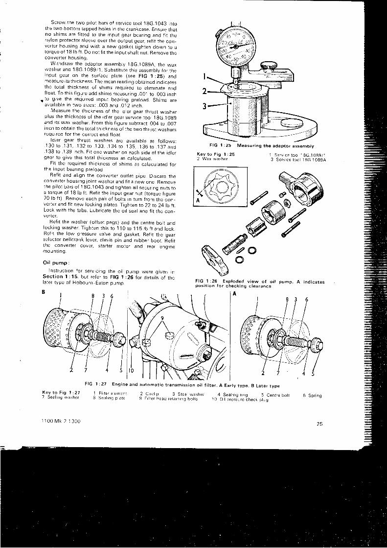
Screw the two p i l o t ba r s o f se r v i ce t oo l 1gG.1043 I n tothe two bot tom tapped holes in the crankcase. Ensure thatno sh ims a re f i t t ed t o t he i npu t gea r bea r i ng and f i t t henylon protector s leeve over the output gear, ref i t the con_verter housing and wi th a new gasket t rghten down to atorque of 18 lb f t . Do not f i t the input shaf t nut . Remove theconve r t e r hous ing .
W i thd raw the adap ro r assemb ly 18G.10994 , t he waxwashe r and 18G.1089 /1 . Subs t i t u t e t h i s assemb ly f o r t hei npu t gea r on t he su r f ace p l a te ( see F IG 1 :25 ) andmeasu re i t s t h i c kness . The mean read i ng ob ra rned i nd i ca testhe tota l th ickness of shims required to e l iminate endf l oa t . To t h i s f i gu re add sh ims measu r i ng . 001 t o . 003 i nch
t t o g r ve t he requ i r ed i npu t bea r i ng p re l oad . Sh ims a reava i l ab l e i n two s i zes ; . 003 and .O ' l 2 i nch .
Measu re t he t h i ckness o f t he i d l e r gea r t h rus t washe rp lus t he t h i ckness o f t he i d l e r gea r se r v i ce t oo l 19G.10g9and r ts wax washer. From this f igure subtract .004 to .007Inch to obtain the tota l th ickness of the two thrust washersrequired for the correct end f loat .
l d l e r gea r t h rus t washe rs a re ava i l ab l e as f o l l ows :1 3 0 t o 1 3 1 , 1 3 2 t o . 1 3 3 , 1 3 4 t o . 1 3 5 , . 1 3 6 t o . 1 3 7 a n d
.138 t o . 139 i nch . F i t one washe r on each s i de o f t he i d l e rgea r t o g i ve t h i s t o t a l t h i c kness as ca l cu l a ted .
F i t t he requ i r ed t h i ckness o f sh jms as ca lacu la ted f o rt he i npu t bea r rng p re l oad .
Ref i t and al rgn the converter out let p ipe. Discard theconve r t e r hous ing j o i n t washe r and f i t a new one . Removethe p i l o t ba r s o f ' 1
8G .1043 and t i gh ten a l l secu r i ng nu t s t oa t o rque o f 18 l b f t . Re f i t t he i npu t gea r nu t ( t o rque f i gu re70 l b f t ) . Remove each pa i r o f bo l t s r n t u rn f r om the con_verter and f i t new locking plates. Tighten to 22 to 24 l t r ILLock wi th the tabs. Lubr icate the oi l seal and f i t the con_verter .
Ref i t the washer (of fset pegs) and the centre bol t andlock i ng washe r . T i gh ten t h i s t o 110 t o 115 l b f t and l ock .Ref i t the low pressure valve and gasket . Ref i t the gearselector bel lcrank lever, c levis p in and rubber boot . Ref i ttne converter cover, star ter motor and rear enqinemoun t i ng .
O i l p u m p :
l ns t r uc t i on f o r se r v i c i ng t he o i l pump we re g i ven i nSec t i on 1 : 15 , bu t r e fe r t o F IG 1 :26 l o r de ta i l s o f t nel a te r t ype o f Hobou rn - Ea ton oumo .
1 : 2 7 E n g i n e
1 F i l t e r e l e m e n t8 S e a l i n g p l a t e
--/)/KC\e
dffw
K e y t o F i g 1 : 2 52 W a x w a s h e r
1 S e r v i c e t o o l 1 8 c . 1 0 8 9 / 13 S e r v i c e t o o l 1 8 G . 1 0 8 9 A
6 S p r i n g
F I G 1 : 2 6 E x p l o d e d v i e w o f o i l p u m p . A i n d i c a t e sp o s i t i o n f o r c h e c k i n g c l e a r a n c e
A
F I G
C i r c l i p 3 S t e e l w a s h e rF i l t e r h e a d r e t a i n i n g b o l t s
: r . A Ear ly type , B La ter type
4 Sea l ing r ing 5 Cent re bo l l1 0 O i l p r e s s u r e c h e c k p l u g
K e y t o F i g 1 : 2 77 Sea l i ng washe r
1 1 0 0 M k 2 1 3 0 0
29
2 5
F I G 1 : 2 5 M e a s u r i n g t h e a d a p t o r a s s e m b l y
a n d a u t o m a t i c t r a n s m i s s i o n o i l f i l t e r
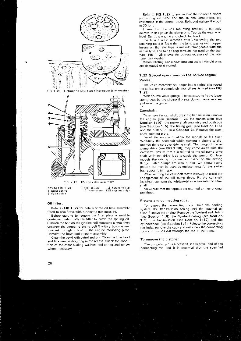
K e y t o F i g 1 : 2 93 Outer spr ing5 V a l v e g u i d e
O i l f i l t e r :
Refer to FIG 1 :27 for detai ls of the oi l f i l ter assemblyf i t ted to cars f i t ted wi th automat ic t ransmissron.
Before star t ing to remove the f i l ter p lace a sui tablecon ta i ne r unde rnea th t he f i l t e r t o ca t ch t he sp i l l i ng o i l .Slacken the bol t on the igni t ton coi l mount ing c lamp, thenunscrew the centra l reta in ing bol t 5 wi th a box spannerinserted through a hole in the engine mount ing plate.
Remove the bowl and element assembly.Clean the bowl wi th petro l and dry. Clean the f i l ter head
and f i t a new seal ing r ing in the recess. Check the condi-t ion of the other seal ing washers and spr ing and renewwnere necessary.
26
1 S p l i t c o t t e r s 2 R e t a i n i n g c u p4 I n n e r s p r i n g ( 1 2 G e n g i n e s o n l y )
Refer to FIG 1:27 to ensure that the correct e lement
and spr ing are f i t ted and that a l l the components are
assembled in the correct order. Ref i t and t ighten the bol t
to 20 lb f t .Ensure that the coi l mount ing bracket is correct iy
located then t ighten the c lamp bol t . Top up the engine ot l
level . Star t the engine and check for leaks.
The f i l ter head is removed af ter unscrewing the two
retain ing bol ts 9. Note that the jo int washer wi th copper
inserts on the later type is not interchangeable wi th the
ear l ier type. The two O-r ing seals are not used on the later
type. FIG 1:28 shows the correct locat ion of the later
type jo int washer.When ref i t t ing, use a new jo int and seals i f the old ones
are damaged or d istor ted.
1 : 22 Spec ia l ope ra t i ons on t he 1275cc eng ine
V a l v e s :
The valve assembly no longer has a spr ing c l tp roundthe col lets and'a completely new oi l seal is used (see FIG1 :29).
With doubie valve spr ings i t is necessary to f i t the lower
spr ing seat before s l id ing th3 seal down the valve stem
and ove r t he gu ide .
C a m s h a f t :
To remove the camshaft . drain the t ransmission, removethe eng ine ( see Sec t i on 1 : 2 ) , t he t r ansm iss i on ( see
Sect ion 1 :10), the rocker shaf t assembly and pushrods( s e e S e c t i o n 1 : 5 ) , t h e t i m i n g g e a r ( s e e S e c t i o n 1 : 6 )
and the dist r ibutor (see Chapter 3) . Remove the cam-sha f t l o ca t i ng p l a te .
lnvert the engine to a l low the tappets to fa l l c lear.Withdraw the camshaft whi le rotat ing i t s lowly to d is-
engage the dist r ibutor dr iv ing shaf t . The f lange of the oi lpump d r i ve ( see F IG 1 :30 ) , may come away w i t h t he
camshaft ; ensure that i t is ref i t ted to the oi l pump dr ive
sha f t w i t h t he dnve l ugs t owa rds t he pump . On l a te r
mode l s t he d r i v i ng l ugs a re cen t ra l i zed on t he d r i v i ngf l ange . La te r pumps a re a l so o f t he two sc rew f i x i ngpa t t e rn bu t may be used as rep lacemen ts f o r t he ea r l i e rf ou r sc rew f i x i ng t ype .
When ref i t t ing the camshaft rotate i t s lowly to assist the
engagement of the oi l pump dr ive. Fi t the camshaftlocat ing plate wi th the whi temetal s ide towards the cam-
shaft .Make sure that the tappets are returned to their or ig inal
posrt rons.
P i s t ons and connec t i ng rods :
To remove the connect ing rods. Drain the cool ing
system, the t ransmission casing and the external o i l
f i l ter . Remove the engine. Remove the f lywheel and c lutch(see Sect ion 1 :8) , the f lywheel casing {see Sect ion1 : 9) , the t ransmission (see Sect ion 1 :10) and the
cvl inder head (see Sect ion 1 :4) . Release the connect ingrod bol ts, remove the caps and wi thdraw the connect ingrods and pistons out through the top of the bores.
To remove t he p i s t ons :
The gudgeon p i n i s a p ress f i t i n t he sma l l end o f t he
connect ing rod and i t is essent ia l that the speci f ied
' i , 1z '; ' l t
' t .
i t " t z ,
i n g t h e l a t e r t y p e f i l t e r c o v e r j o i n t w a s h e r
F I G 1 : 2 9 1 2 7 5 c c v a l v e a s s e m b l v
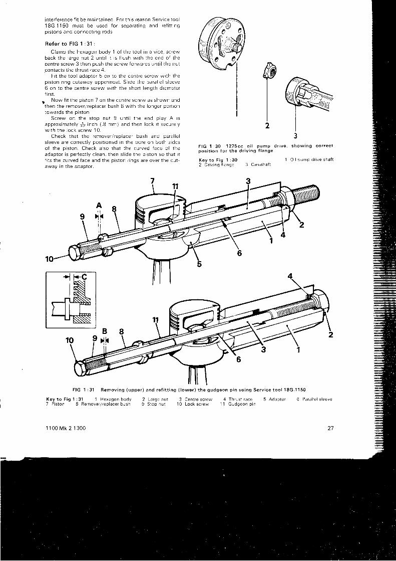
i n t e r f e rence f i t be marn ta rned . Fo r t h i s r eason Se rv i ce t oo l18G.1150 mus t be used f o r sepa ra t i ng and re t i t t i ngp i s t ons and connec t i ng rods .
R e f e r t o F I G 1 : 3 1 :
C lamp the hexagon body 1 o f t he t oo l i n a v i ce , sc rewback t he l a rge nu t 2 un t i l i t i s f l u sh w i t h t he end o f t hecen t re sc rew 3 t hen push t he sc rew fo rwa rds un t i l t he nu tcontacts the thrust race 4.
F i t t he t oo l adao to r 5 on t o t he cen t re sc rew w i t h t hep i s t on r i ng cu taway uppe rmos t . S l i de t he pa ra l l e l s l eeve6 on t o t he cen t re sc rew w i t h t he sho r t l enq th d i ame te rfr rst.
. Now f i t t he p i s t on 7 on t he cen t re sc rew as shown andthen t he remove r / r ep lace r bush B w i t h t he I onge r po r t i ontowa rds t he p i s t on .
Sc rew on t he s top nu t 9 un t i l t he end p l ay A i sapp rox ima te l y j . i n ch ( . 8 mm) and t hen l ock i t secu re l yw i t h t he l ock sc rew 10 .
Check t ha t t he remove r / r ep lace r bush and oa ra l l e ls l eeve a re co r rec t l y pos i t i oned i n t he bo re on bo th s i deso f t he p i s t on . Check a l so t ha t t he cu rved f ace o f t headap to r i s pe r f ec t l y c l ean , t hen s l i de t he p i s t on so t ha t i tf i t s t he cu rved f ace and t he D i s ton r i nqs a re ove r t he cu t -away in the adaptor.
PI2
3F I G 1 : 3 0 1 2 7 5 c c o i l p u m p d r i v e , s h o w i n g c o r r e c tp o s i t i o n f o r t h e d r i v i n g f l a n g e
Key t o F i g 1 : 302 D r r v i ng f l ange 3 CamshaJ t
1 O i l p u m p d r i v e s h a f l
F IG 1 : 31 Remov ing (uppe r ) and re f i t t i ng ( l owe r ) t he gudgeon p i n us i ng Se rv i ce t oo l 18G.1150
K e y t o F i g 1 : 3 1 1 H e x a g o n b o d y7 P is ton 8 Bemover / rep lacer bush
1 1 0 0 M k 2 1 3 0 0
2 L a r g e n u t 3 Cent re screw1 0 Lock screw
4 T h r u s t r a c e 5 A d d p t o r1 1 G u d g e o n p i n
6 Para l le l s leeve
27

9 5 1 4 8F I G 1 : 3 2 R e l e a s e a n d t i g h t e n i n g s e q u e n c e s f o r t h ecy f i nde r head nu t s on1275 cc eng ines . The a r rows A andB i nd i ca te t he add i t i ona l bo l t and nu t f i t t ed t o 9 .75 :1compress ion ra t i o eng ines
Sc rew the l a rge nu t up t o t he t h rus t r ace , t hen ho ldthe l ock sc rew and t u rn t he nu t un t i l t he gudgeon p i n hasbeen w i t hd rawn f r om the p i s t on .
Re f i t t i ng t he p i s t ons :
Remove t he l a rge nu t 2 f r om the t oo l and pu l l t hecen t re sc rew 3 ou t o f t he body by a f ew i nches . t nens l i de t he pa ra l l e l s l eeve 6 , l onge r l eng th d i ame te r f i r s t , onto t he cen t re sc rew up t o t he shou lde r on t he sc rew .
App l y a coa t i ng o f g raph r t ed o i l t o t he gudgeon p i nand t he bo res o f t he connec t i ng rod and p i s t on , t henp lace t he p i s t on ove r t he connec t i ng rod and f i t t he t oo l t ot he p i s t on , i nse r t i ng t he pa ra l l e l s l eeve i n t o t he sma l l endbo re as f a r as t he g roove rn t he s l eeve . F i t t he gudgeon p rni n to t he p i s t on bo re as i a r as t he connec t i nq rod .
Fi t the remover l replacer bush wi th iG short endtowa rds t he gudgeon p i n . Sc rew the s top nu t on t o t hecen t re sc rew un t i l t he re i s . ! i n ch ( . 8 mm) end p l ay Band l ock i t w i t h t he l ock sc rew 10 .
C lean t he cu rved f ace o f t he adap to r and s l i de t hep i s t on i n t o con tac t w i t h i t and check t ha t t he p i s t on r i ngsare over the cutaway port ion.
F i t and sc rew the l a rge nu t up t o t he t h rus t r ace .The m in imum l oad f o r an accep tab le f i t i s 16 l b f t .
Se t t he t o rque w rench t o t h i s f t gu re and wh i l e ho ld i ngthe l ock sc rew w i t h ano the r spanne r , pu l l t he gudgeonp rn i n by t u rn i ng t he l a rge nu t un t i l t he f l ange o i t he
remove r / r ep lace r bush i s - i n ch ( . 8 mm) f r om thep i s ton sk i r t C . On no accoun t mus t t he f l ange con tac t t hep i s t on .
l f t he t o rque w rench does no t b reak du r i ng t h i sope ra t ron , t he f i t i s no t accep tab le and t he componen tsmust be renewed. Keep the large nut and the cerr t re screwwe l l o i l ed o r a f a l se r eac t i on mav resu l t .
Connec t i ng rods :
These are f i t ted in the reverse order of removal , butno te t he f o l l ow ing po in t s :
Check t ha t t he p i s t on r i ng gaps a re s tagge red a t gO deg .t o each o the r and t ha t each connec t i ng rod and p i s t on i sre f i t t ed i n t o i t s o r i g i na l bo re t he co r rec t way round .
The b i g -end bea r i ngs a re no t i nc l i ned as i n F IG 1 : 1bbu t t hey a re s im i l a r l y o f f se t . Nos . 1 and 3 a re o f f se ttowards the rear of the engine, 2 and 4 are of fset towardsthe f r on t
Se l f - l ock i ng nu t s a re used on t he b i g -end bo l t s ,check t ha t t hey do l ock sa t i s f ac to r i l y and t i gh ten t hem to ato rque o f 35 t o 38 l b f r w i t h t he t h reads l i gh t l y o i l ed .
P i s t on s i zes :
I n add i t i on t o t he s tanda rd p i s t ons , two ove rs i zesa r e a v a i l a b l e . D i m e n s i o n s a r e i n d i c a t e d i n a s i m i l a rm a n n e r t o t h e s m a l l e r e n g i n e .Pistonmarktng Suitable bore srze
Grade BGrade AS t a n d a r d 2 1 8 O 5 t o 2 . l 8 1 O 2 . 1 8 i 1 t o 2 . 7 8 1 6 i n c h
(10 .625 t o 70 635 ) ( 70 .640 t o 70 .65b ) mm+ . 0 1 0 i n c h 2 . l 9 0 5 t o 2 . 7 9 1 O 2 . i 9 1 1 r o 2 . 7 9 1 6 i n c h( + . 2 5 5 m m )
(70 .880 ro 70 .890 ) ( 70 .895 t o 70 .905 ) mm+.020 i nch 2 .8005 t o 2 .801 0 2 .801 1 r o 2 .801 6 i ncn( + . 5 1 0 m m )
( 7 1 . 1 3 5 r o 7 1 1 4 5 ) ( 7 1 1 5 0 t o 7 1 . 1 6 0 ) m m
C y l i n d e r h e a d :
1275 cc eng ines w i t h a 9 .75 :1 compress ion ra t i o a ref i t t ed w i t h an ex t r a s t ud and an ex t r a bo l t a t each end o ft he cy l i nde r head . The add i t i ona l nu t and bo l t a re f i t t edand removed i ndependen t l y .
When re f i t t i ng t he head , t i gh ten t he ma in nu t s f i r s t r nt he sequence g i ven i n F IG 1 : 32 t o a t o rque o f 48 t o 52 l bf t and t hen t he add i t i ona l nu t t o t he same to rque and t hebol t to 25 lb f t
1 : 2 3 O i l c o n t r o l p i s t o n r i n g s
Ea r l y mode l s o f t he 1275 cc eng ine and l a t e r mode l s o ft he 1098 cc we re f i t t ed w i t h Dua f l ex o i l con t ro l r i ngs .When f i n i ng t hem the f o l l ow ing po rn t s shou ld be no ted :T h e f i t t e d g a p f o r t h e r a i l s i s . 0 1 2 t o . 0 2 8 i n c h . w h i l et he gap f o r t he s i de sp r i ng shou ld be be tween .100 and'1
50 i nch .The l ugs o f t he expande r mus t be bu t t ed t oge the r and
no t c rossed and i nsened i n t o one o f t he ho les i n t hesc rape r r i ng g roove on t he non - t h rus t ( camsha f t ) s i de o ft he p i s t on .
When compress ing t he r i ngs p r i o r t o f i t t i ng , make su retha t t he end o f each r i ng i s f u l l y home rn i t s g roove .
See t ha t t he gaps i n t he tw in r a i l s and t he s i de sp r rnga re s tagge red on t he non - t h rus t s i de o f t he p i s t on .
121
F I G 1 : 3 3 D e t a i l s o f t h e A p e x o i l c o n t r o l p i s t o n r i n g .A s h o w s t h e e n d s o f t h e e x p a n d e r b u t t e d t o g e t h e r ,B s h o w s a c r o s s - s e c t i o n t h r o u g h t h e a s s e m b l e d r i n g s
I R a i l r n g s 2 S p a c e r e x p a n d e r r i n gKey t o F i g 1 : 33
28
A
2
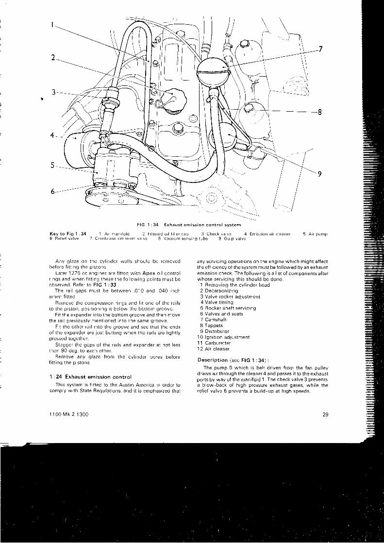
l-'g
F I G 1 : 3 4 E x h a u s t e m i s s i o n c o n t r o l s v s t e m
K e y t o F i g l : 3 4 1 A i r m a n i f o l d 2 F r l t e r e d o i l f i l l e r c a p 3 C h e c k v a l v e 4 E m i s s i o n a i r c l e a n e r 5 A i r p u m p6 R e l i e f v a l v e 7 C r a n k c a s e e m i s s r o n v a l v e 8 V a c u u m s e n s i n o t u b e 9 G u l o v a l v e
6-t t
Any g l aze on t he cy l i nde r wa l l s shou ld be removedbefore f i t t ing the pistons.
La te r 1275 cc eng ines a re f i t t ed w i t h Apex o i l con t ro lr i ngs and when f i t t i ng t hese t he f o l l ow ing po in t s mus t beobse rved . Re fe r t o F IG 1 : 33 .
The ra i l gaps mus t be be tween . 010 and . 040 i nchwhen f i t t ed .
Remove t he compress ion r i ngs and f i t one o f t he ra i l st o t he p i s t on , pos i l i on i ng i t be l ow t he bo t t om g roove .
F i t t he expande r i n t o t he bo t t om g roove and t hen movethe ra i l p rev i ous l y men t i oned i n t o t he same g roove .
F i t t he o the r r a i l i n t o t he g roove and see t ha t t he endso f t he expande r a re j us t bu t t i ng when t he ra t l s a re l i gh t l ypressed together.
S tagge r t he gaps o f t he ra i l s and expande r a t no t l essthan 90 deg . t o each o the r
Remove any g l aze f r om the cy l i nde r bo res be fo ref i t t i ng t he p i s t ons .
1 : 24 Exhaus t em iss i on con t ro l
This system is f i t ted to the Aust in America in order tocomp ly w i t h S ta te Requ la t i ons , and i t i s emphas i zed t ha t
1 1 0 0 M k 2 1 3 0 0
\
any serv ic ing operat ions on the engine which might af fectthe ef f ic iency of the system must be fo l lowed by an exhaustemission check. The fo l lowing is a l is t of components af terwhose se rv i c i ng t h i s shou ld be done :
1 Remov ing t he cy l i nde r head1 n ^ ^ ^ - L ^ ^ i - l ^ ^L U Y U d t U V t | L | t 9
3 Valve rocker adjustment4 Va l ve t im ing5 Rocker shaf t serv ic ing6 Valves and seats7 Camshaft8 Tappets9 D i s t r i bu to r
10 l gn i t i on ad jus tmen t1 1 Carburet ter1 2 A i r c l e a n e r
Desc r i p t i on ( see F IG 1 : 34 ) :
The pump 5 wh i ch i s be l t d r i ven f r om the f an pu l l eydraws air through the c leaner4 and passes i t to the exhaustports by way of the mani fo ld 1. The check valve 3 preventsa blow-back of h igh pressure exhaust gases, whi le therel ief valve 6 prevents a bui ld-up at h igh speeds.
l \ l J\Y_/
29
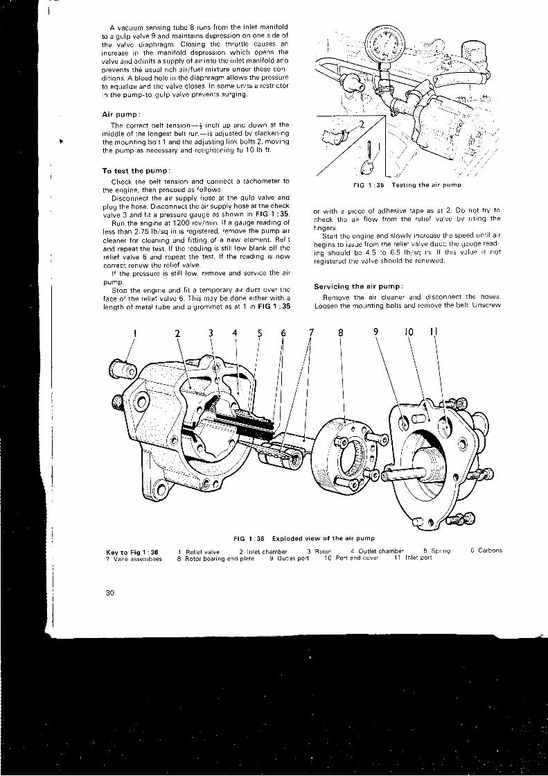
A vacuum sens ing t ube 8 r uns f r om the i n l e t man i f o l d
to a gulp valve 9 and maintains depression on one s ide of
the valve diaphragm. Closing the throt t le causes anincrease in the mani fo ld depression which opens the
va l ve and adm i t s a supp l y o f a i r i n t o t he i n l e t man i f o l d andprevents the usual r ich ai r l fuel mixture under these con-
di t ions. A bleed hole in the diaphragm al lows the pressure
to eoual ize and the valve c loses. In some uni ts a restr ic tori n t he pump- to -gu lp va l ve p reven t s su rg i ng .
A i r p u m p :
The correct bel t tension- | inch up and down at themiddle of the longest bel t run- is adjusted by s lackenrngthe mount ing bol t 1 and the adjust ing l ink bol ts 2, movingthe pump as necessary and ret ightening to 1 0 lb f t .
To t es t t he pump :
Check the bel t tension and connect a tachometer to
the engine, then proceed as fo l lows:Disconnect the ai r supply hose at the gulp valve and
plug the hose. Drsconnect the ai r supply hose at the checkva l ve 3 and f i t a p ressu re gauge as shown i n F IG 1 : 35 .
Run t he eng ine a t 1200 rev lm in . l f a gauge read ing o fless than 2.15 lb lsq in is registered, remove the pump alr
c leaner for c leaning and f i t t ing of a new element. Ref i tand repeat the test . l f the reading is st i l l low blank of f therel ief valve 6 and repeat the test . l f the reading is nowcorrect renew the re l ief valve.
l f the pressure is st i l l low, remove and servrce the ai rpump .
Stop the engrne and f i t a temporary a i r duct over theface o f t he re l i e f va l ve 6 . Th t s may be done e i t he r w i t h al eng th o f me ta l t ube and a g rommet as a t 1 i n F IG 1 : 35
F I G 1 : 3 5 T e s t i n g t h e a i r P u m P
or wi th a p iece of adhesive tape as at 2. Do not t ry to
check the ai r f low f rom the re l ief valve by using the
f i nge rs .S ta r t t he eng ine and s l ow l y i nc rease t he speed un t i l a i r
begrns to issue f rom the re l ief valve duct ; the gauge read
ing shou ld be 4 .5 t o 6 .5 l b i sq i n . l f t h i s va l ue i s no tregistered the valve should be renewed.
S e r v i c i n g t h e a i r p u m p :
Remove the ai r c leaner and disconnect the hoses.
Loosen the mount ing bol ts and remove the bel t . Unscrew
F IG 1 :36 Exp loded v i ew o f t he a i r pump
Key t o F i g 1 : 367 Vane assembl ies
30
18
Bel ie f va lve 2 In le t chamber 3Rotor bear ing end p la te 9 Out le t por t
4 O u t l e t c h a m b e r 5 S p r i n gPor t end cover 11 ln le l por t
Rotor1 0
6 C a r b o n s
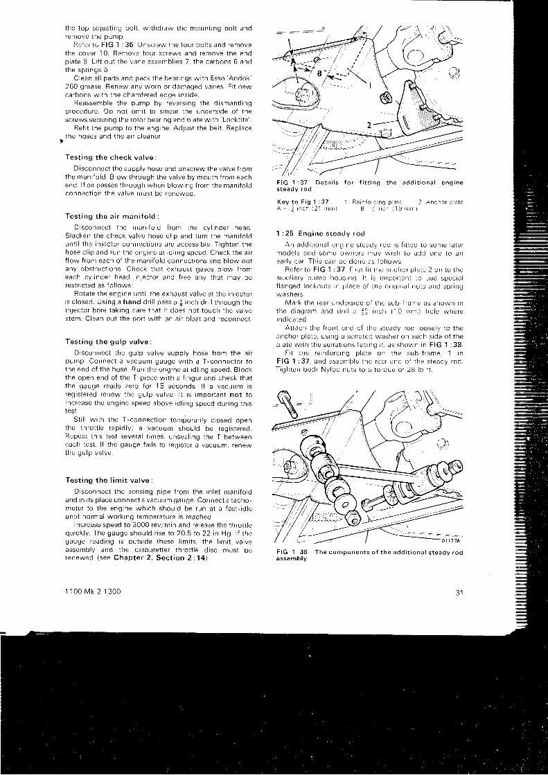
t he t op adJus t rng bo l t , w r t hd raw the moun t i ng bo l t andremove t he pump .
Re fe r t o F IG 1 : 36 Unsc rew the f ou r bo l t s and removethe cove r 10 . Remove f ou r sc rews and remove t he endp la te B L i f t ou t t he vane assemb l i es 7 , t he ca rbons 6 andthe sp r i ngs 5 .
C lean a l l pa r t s and pack t he bea r i ngs w i t h Esso 'Andok '
260 g rease . Renew any wo rn o r damaged vanes . F i t newca rbons w i t h t he chamfe red edge i ns i de
Reassemb le t he pump by reve rs i ng t he d i sman t l r ngp rocedu re . Do no t om i t t o smea r t he unde rs i de o f t hesc rews secu r i ng t he ro to r bea r i ng end p l a te w i l h ' Lock t i t e '
Re f i t t he pump to t he eng ine Ad lus t t he be l t . Rep lacethe hoses and t he a i r c l eane r .
Tes t i ng t he check va l ve
D isconnec t t he supp l y hose and unsc rew the va l ve f r omthe man i f o l d . B l ow t h rough t he va l ve by mou th f r om eachend . l f a i r passes t h rough when b l ow ing f r om the man i f o l dconnec t i on t he va l ve mus t be renewed .
Tes t i ng t he a i r man i f o l d :
D i sconnec t t he man i f o l d f r om the cy l i nde r head .S lacken t he check va l ve hose c l i p and t u rn t he man i f o l dun t i l t he i nJec to r connec t i ons a re access ib l e . T i gh ten t hehose c l i p and run t he eng rne a t i d l i ng speed . Check t he a i rf l ow f r om each o f t he man i f o l d connec t i ons and b l ow ou tany obs t ruc t i ons . Check t ha t exhaus t gases b l ow f r omeach cy l i nde r head i n l ec to r and f r ee any t ha t may beres t r r c t ed as f o l l ows :
Ro ta te t he eng ine un t i l t he exhaus t va l ve a t t he i n l ec to ri s c l osed . Us ing a hand d r i l l pass a $ i nch d r i l l t h rough t hein l ec to r bo re t ak i ng ca re t ha t i t does no t t ouch t he va l ves tem. C lean ou t t he po r t w i t h an a i r b l as t and reconnec t .
Tes t i ng t he gu lp va l ve :
D i sconnec t t he gu lp va l ve supp l y hose f r om the a i rpump . Connec t a vacuum gauge w i t h a T - connec to r t ot he end o f t he hose . Run t he eng ine a t i d l i ng speed . B lockthe open end o f t he T -p i ece w i t h a f i nge r and check t ha tt he gauge reads ze ro f o r 15 seconds . l f a vacuum r sreg i s t e red renew the gu lp va l ve . l t t s impo r tan t no t t ornc rease t he eng ine speed above i d l i ng speed du r i ng t h i sIest .
S t i l l w i t h t he T -connec t i on t empo ra i l l y c l osed openthe t h ro t t l e r ap id l y ; a vacuum shou ld be reg i s t e red .Repea t t h i s t es t seve ra l t imes , unsea l i ng t he T be tweeneach t es t . I f t he gauge f a i l s t o r eg i s t e r a vacuum, r enewt h e g u l p v a l v e .
Tes t i ng t he l im i t va l ve :
D i sconnec t t he sens ing p i pe f r om the i n l e t man i f o l dand i n i t s p l ace connec t a vacuum gauge . Connec t a t acho -me te r t o t he eng ine wh i ch shou ld be run a t a f as t - i d l eun t i l no rma l wo rk i ng t empe ra tu re i s r eached .
Increase speed to 3000 revlmin and re lease the throt t lequ i ck l y . The gauge shou ld r i se t o 20 .5 t o 22 i n Hg . l f t hegauge read ing i s ou t s i de t hese l im i t s , t he l im i t va l veassembly and the carburet ter throt t le d isc must berenewed ( see Chap te r 2 , Sec t i on 2 :14 ) .
1 1 0 0 M k 2 1 3 0 0
F I G 1 : 3 7 D e t a i l s f o r f i t t i n g t h e a d d i t i o n a l e n g i n es teady rod
Key t o F i g 1 : 37 1 Re in fo r c ng p a t c 2 Ancho r p a teA - 1 : i n c h ( 2 1 m m ) B j n c h ( ' 1 9 m m l
1 : 2 5 E n g i n e s t e a d y r o d
An add i t i ona l eng ine s teady rod i s f r t t ed t o some l a te rmode l s and some owne rs may w i sh t o add one t o anea r l y ca r . Th i s can be done as f o l l ows :
Re fe r t o F IG 1 : 37 . F i r s t f i t t he ancho r p l a te 2 on t o t heaux r l i a r y pump hous ing . l t i s impo r tan t t o use spec ia lf l a n g e d l o c k n u t s r n p l a c e o f t h e o r i g i n a l n u t s a n d s p n n gwashe rs .
Ma rk t he rea r unde rs rde o f t he sub f r ame as showr r r nt h e d i a g r a m a n d d r i l l a f i i n c h ( 1 C m m ) h o l e w h e r ei nd i ca ted .
A t t ach t he f r on t end o f t he s teady rod l oose l y t o t heancho r p l a te , us i ng a se r ra ted washe r on each s i de o f t hep la te w i t h t he se r ra t i ons f ac i ng r t , as shown i n F IG 1 : 38
F i t t he re i n fo r c i ng p l a te on t he sub { r ame . 1 r nF IG 1 : 37 , and assen rb le t he rea r end o f t he s teady rod .T igh ten bo th Ny loc nu t s t o a t o rque o f 28 l b f t .
F I G 1 : 3 8 T h e c o m p o n e n t s o f t h e a d d i t i o n a l s t e a d v r o da s s e m b l v
J I
o | \ 7 7 4
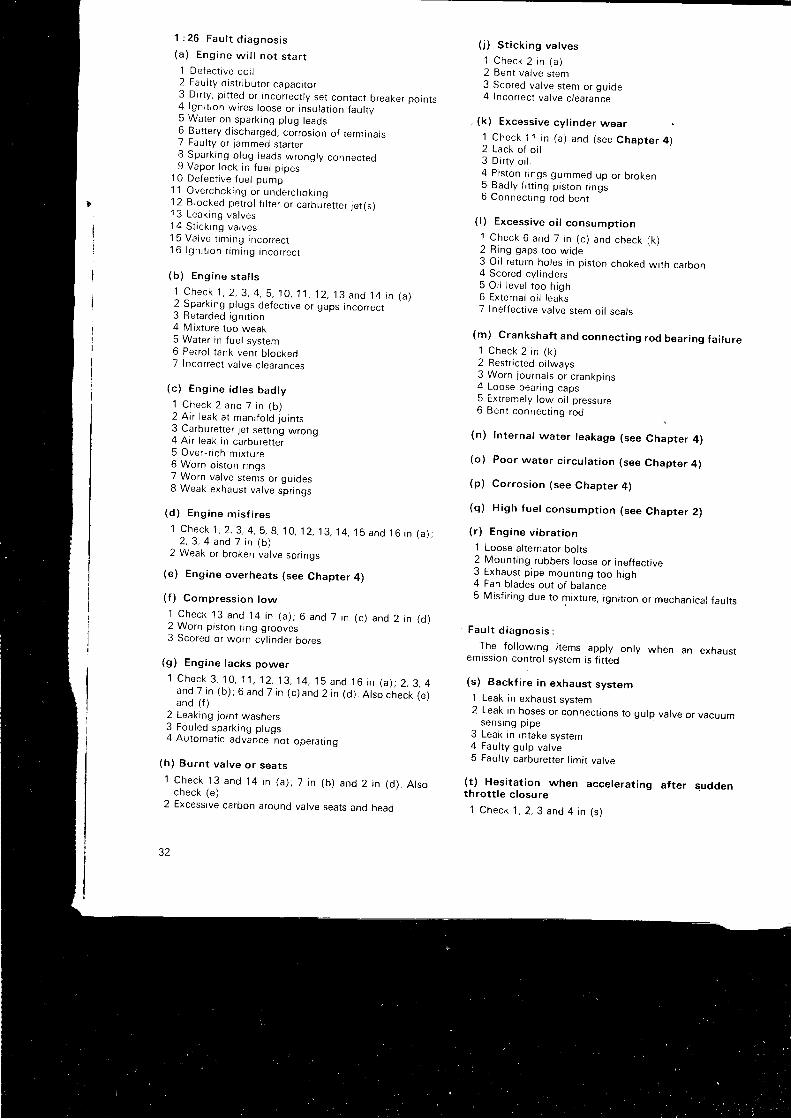
1 : 2 6 F a u l t d i a g n o s i s
( a ) E n g i n e w i l l n o t s t a r t
1 De fec t i ve co i l2 Fau l t y d i s t r i bu to r capac r t o r3 Dir ty, p i t ted or incorrect ly set contact breaker points4 l gn i t i on w i res l oose o r i nsu la t i on f au l t y5 Water on sparking plug leads6 Battery d ischarged, corrosion of termrnals7 Faul ty or jammed starrer8 Spa rk i ng p l ug l eads w rong ry connec ted9 Vapor lock in fuel p ipes
10 De fec t i ve f ue l pump1 1 Ove rchok ing o r unde rchok ing1 2 Blocked petro l f i l ter or carbuiet ter jet (s)1 3 Leaking valves14 S t i c k i ng va l ves15 Va l ve t tm ing i nco r rec t1 6 l gn i t i on t im ing i nco r rec t
( b ) Eng ine s ta l l s
1 C h e c k 1 , 2 , 3 , 4 , S , 1 0 , 1 1 , 1 2 , 1 3 a n d 1 4 i n ( a )2 Sparking plugs defect ive or gaps incorrect3 Re ta rded i gn i t i on4 Mixture too weak5 Water in fuel system6 Petrol tank vent b lockeo7 Incorrect valve c learances
(c ) Eng ine i d t es bad t y
1 Check 2 and 7 i n ( b )2 A r r l eak a t man i f o l d j o i n t s3 Carburet ter jet set t ing wrong4 Air leak in carburet ter5 Ove r - r i ch m i x tu re6 Worn piston r ings7 Worn va l ve s tems o r qu ides8 Weak exhaust valve s-pr ings
(d ) Eng ine m is f i r es
1 C h e c k 1 , 2 , 3 , 4 , S , 8 , 1 0 , 1 2 , 1 3 , 1 4 , 1 5 a n d 1 6 i n ( a / ;2 , 3 , 4 and 7 i n ( b )
2 Weak or broken valve spr ings
(e ) Eng ine ove rhea t s ( see Chap te r 4 )
( f ) Compress ion l ow
l , C h e c k 1 3 a n d 1 4 i n ( a ) ; 6 a n d 7 i n ( c ) a n d 2 i n ( d )2 Worn piston r ing grooves3 Scored or worn cyl inder bores
(g ) Eng ine l acks power
1 C h e c k 3 , 1 0 , 1 1 r , 1 2 , 1 3 , 1 4 , 1 5 a n d 1 6 i n ( a ) ; 2 , 3 , 4and 7 i n ( b ) ; 6 anO 7 i n ( c ) and 2 i n ( d ) . A t so check 1e .1and ( f )
2 Leaking jo int washers3 Fou led spa rk i ng p l ugs4 Automattc advance not operat ing
(h ) Bu rn t va l ve o r sea t s
1 Check 13 and 14 i n ( a ) ; 7 i n ( b ) and 2 i n ( d ) . A l socheck (e )
2 Excessive carbon around valve seats and head
2 )
( . i ) S t i c k i ng va l ves
1 Check 2 i n ( a )2 Ben t va l ve s tem3 Scored valve stem or guide4 Incorrect valve c learance
. (k) Excessive cyl inder wear1 Check 1 1 i n ( a ) and ( see Chap te r 4 )2 Lack of o i l3 D i r t y o i l4 P i s t on r i ngs gummed up o r b roken5 Bad l y f i t t i ng p i s t on r i ngs6 Connectrng rod bent
( l ) Excess i ve o i l consump t i on
1 Check 6 and 7 i n ( c ) and check ( k )2 R ing gaps t oo w ide3 Oi l return holes in p iston choked wi th carbon4 Scored cyl inders5 O i l l e ve l t oo h i gh6 External o i l leaks7 Inef fect ive valve stem oi l seals
(m) Crankshaft and connect ing rod bear ing fa i lure1 Check 2 i n ( k )2 Restr ic ted oi lways3 Worn j ou rna l s o r c rankp ins4 Loose bear ing caps5 Extremely low oi l pressure6 Ben t connec t i ng rod
(n) lnternal water leakage (see Chapter 4)
(o ) Poo r wa te r c i r cu l a t i on ( see Chap te r 4 )
(p ) Co r ros i on ( see Chap te r 4 )
(q ) H igh f ue l consump t i on ( see Chap te r 2 )
( r ) Eng ine v i b ra t i on
1 Loose al ternator bol ts2 Mount ing rubbers loose or inef fect ive3 Exhaus t p i pe moun t i ng t oo h i gh4 Fan blades out of bala-nce5 Misf i r ing due to mixture, igni t ion or mechanical faul ts
F a u l t d i a g n o s i s :
The fo l lowing i tems apply only when an exhaustemission contro l system is f i t ted
(s) Backf i re in exhaust system1 Leak in exhaust system2 Leak in hoses or connect ions to gulp valve or vacuum
sens ing p i pe3 Leak in intake system4 Fau l t y gu lp va l ve5 Faul ty carburet ter l imi t varve
(t ) Hesi tat ion when accelerat ing af ter suddenthrot t le c losure
1 C h e c k 1 , 2 , 3 a n d 4 i n 1 s . 1
(w ) Bu rned o r baked hose be tween a i r pump andcheck valve
1 Fau l t y check va l ve2 Fau l t y a r r pump
( x ) N o i s y a i r p u m p
1 Be l t t ens ion i nco r rec t2 Pu l l ey l oose o r m i sa l i gned3 Damaged a i r pump
1 1 0 0 M k 2 1 3 0 0
( y ) H igh exhaus t sys tem tempe ra tu re
1 l nco r rec t i gn i t i on t im ing2 A i r i n j ec to r m i ss i ng3 Fau l t y a i r pump re l i e f va l ve
( z ) M i x tu re needs en r i chmen t t o ob ta i n co r rec texhaus t em iss i on read ing
1 A i r l eak i n c rankcase2 Leaks in crankcase breather hose or carburet ter con-
nect ions
CHAPTER 2
T H E F U E L S Y S T E M
2 : 1 Desc r i p t i on2 : 2 R o u t i n e m a i n t e n a n c e2 : 3 P u m p r e m o v a l a n d d i s m a n t l i n g2 : 4 E x a m i n a t i o n o f p u m p2 : 5 Reassemb ly o f pump2 : 6 T e s t i n g t h e p u m p2:7 Operat ion of the SU carburet ter2 :8 Remov ing and se rv i c i ng t he ca rbu re t t e r2 : 9 Cen t ra l i z i ng t he j e t
2 : 1 Desc r i p t i on
A l l t he mode l s cove red by t h i s manua l a re f i t t ed w i t hSU fuel pumps and SU carburet ters. Two tvpes ofe l ec t r i ca l pump a re used and one mechan i ca l t ype . The reare also two types of carburet ter but their operat ion iss im i l a r and one se t o f i n s t r uc t i ons w i l l su f f i ce . Whe redetai ls vary. the necessary informat ion wi l l be given.
The e l ec t r r c f ue l pumps a re t he t ypes SP and AUF 200 .The mechan i ca l pump i s t he AUF 700 and i s f i t t eo r os i ng le ca rbu re t t e r Mk 3 mode l s on l y .
On 1098 cc eng rnes f i t t ed w i t h synch romesh t r ans -mission HS2 carburet ters are f i t ted, e i ther s ingle or twinacco rd i ng t o t he ca r . On 1275 cc eng ines and a l l au to -ma t i c t r ansm iss i on mode l s e i t he r tw in H52 o r a s i ng le H54are used. The GT cars have twin H52 carburet ters.
2 : 2 R o u t i n e m a i n t e n a n c e
The on l y i t em unde r t h i s head ing i s a check eve ry 3000mi les of the level of lubr icant in the hol low piston rod andtopping up i f required. Unscrew the cap f rom the top ofthe depression chamber and see that the level is * inchf rom the t op as shown i n F IG 2 :8 . Top up w i t h t n rneng ine o i l on l y .
1 1 0 0 M k 2 1 3 0 0
2 : 1 0 S l o w - r u n n i n g a d j u s t m e n t2 : 11 Tw in ca rbu re t t e r l i n kage2 : 12 Ca rbu re t t e r f au l t s2 : ' l 3 Th ro t t l e damper . 1275 cc eng ines2 : 1 4 E x h a u s t e m i s s i o n c o n t r o l2 : 1 5 A i r c l e a n e r2 : 1 6 M e c h a n i c a l f u e l p u m p2 : 1 7 F a u l t d i a g n o s i s
2 : 3 P u m p r e m o v a l a n d d i s m a n t l i n g
The f ue l pump w i l l be f ound i ns i de t he l uggage com_pa r tmen t on t he r i gh thand s i de . Fo r r emova l , d i s connec rthe bat tery earth lead and f rom underneath the car d is_connec t t he i n l e t and ou t l e t connec t i ons l eav ino t nef l ex i b l e hoses on t he pump connec t i ons . L i f t t he l u j gagecompartment f loor and remove the screws secur inq rnepump mouht ing bracket to the body. L i f r out the plumpand d i sconnec t t he e l ec t r i c cab le .
D i s m a n t l i n g ( r e f e r t o F I G 2 : 1 ) :
Remove the terminal parts 30 to 33 and the seal 43.Li f t of f the cover 29. Remove the contact b lade 22.Remove the housing screws 7 and the earth ing screw 9.Separate the housing 6 f rom the body 1, or 44 on type Sp.
Unsc rew the d i aph ragm 2 i n an an t i c l ockw i se d i r ec t r onwhi le hold ing the assembly over the bench to catch theeleven brass ro l lers which wi l l drop away. Do not separatethe d i aph ragm f r om i t s sp i nd te .
Remove the washer 21 and nut 20. The lead washer 1 9wi l l have to be cut away. Remove the two screws 29 andtake of f the earth terminal tag 13, t ip the pedestal 16 and
35
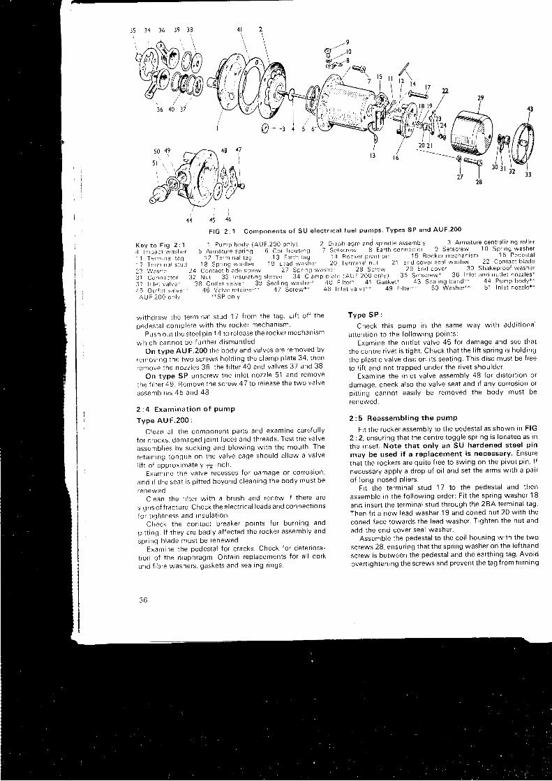
35 14 36 39 38
?,@Mo/bww36 40 37
@=-: 4
i )45 46
K e y t o F i g 2 : 1, 1 l m p a c t w a s h e r1 1 T e r m r n a l t a gT 7 T e r n r n a l s t u d2 3 W a s h e t3 1 C o n n e c t o r3 7 I n l e t v a l v e '4 5 O u t l e t v a l v e ' '
A U F 2 0 0 o n l y
wi thd raw the t e rmrna l s t ud 17 f r om the t ag L i f t o f f t he
oedes ta l comp le te w i t h t he rocke r mechan l sm
Push ou t t he s tee l p i n 1 4 t o r e l ease t he rocke r mechan i sm
wh ich canno t be f u r t he r d i sman t l ed
On type AU F.200 the body and valves are removed by
remov ing t he lwo sc rews ho ld i ng t he c l amp p la te 34 , t hen
remove the nozzles 36, the f i l ter 40 and valves 37 and 38
On t ype SP unsc rew the i n l e t nozz le 51 and remove
the f i l ter 49 Remove the screw 47 to re lease the two valve
assemb l t es 45 and 48 .
2 : 4 E x a m i n a t i o n o f P u m P
Type AU F .200 :
C lean a l l t he componen t pa r t s and exam ine ca re {u l l y
f o r c racks , damaged l o i n t f aces and t h reads Tes t t he va l ve
assemb l i es by suck ing and b l ow ing w i t h t he mou th The
re ta i n i ng t ongue on t he va l ve cage shou ld a l l ow a va l ve
l i f t o i app rox ima te l y { i n ch .Exam ine t he va l ve recesses f o r damage o r co r ros i on ,
and i f t he sea t i s p i t t ed beyond c l ean ing t he body mus t be
renewedC lean t he f i l t e r w i t h a b rush and renew i f t he re a re
sig ns of f ractu re. C heck the electr ical leads and con nect ions
fo r t i gh tness and i nsu la t i on .Check t he con tac t b reake r po in t s f o r bu rn i ng and
pi t t ing. l f they are badly af fected the rocker assembly and
sp r i ng b l ade mus t be renewed .Exam ine t he pedes ta l f o r c racks . Check f o r de te r i o ra -
t i on o f t he d i aph ragm. Ob ta i n r ep lacemen ts f o r a l l co r k
and f i b re washe rs , gaske t s and sea l i ng r i ngs
3 6
F I G 2 : 1 C o m p o n e n t s o f S U e l e c t r i c a l f u e l p u m p s T y p e s S P a n d A U F 2 0 0
1 p u m p b o d y ( A U F 2 O O o n l y ) 2 D r a p h r a g m a n d s p i n d l e a s s e m b l y ^ ^ 3 A r m a t u r e c e n t r a l i z i n g r o l l e r
5 A r m a t u i e s p r i n g G C o i l h o u s i n g 7 S e i s c r e w 8 E a r t h c o n n e c t o r 9 S e t s c r e w 1 0 S p r i n g w a s h e r
1 2 T e r m r n a l t a g " 1 3 E a r t h t a [ 1 4 R o c k e r p t v o t p i n 1 5 R o c k e r . m e c h a n i s m 1 6 P e d e s t a l
1 g S p r i n g w a s h 6 r l 9 L e a d w a s " h e r 2 O T e r m i n a l n u t 2 1 E n d c o v e r s e a l w a s h e r 2 2 C o n t a c t b l a d e
2 4 C o n t a c t b t a d e s c r e w 2 7 S p r r n g w a s h e r 2 8 S c r e w 2 9 E n d c o v e r 3 0 S h a k e p r o o f w a s h e r
3 2 N u t 3 3 I n s u i a t i n g s l e e v e 3 a C i a m p p i a t e ( A U F 2 0 0 o n l y ) 3 5 S e - t s c - r e w ' * . 3 6 I n l e t a n d o u t l e t n o z z l e s x
3 g O u t l e r v a l v e - 3 b S e a t i n g w a s h e r l ' 4 0 F i l t e r * 4 1 G a s k e t * 4 3 S e a l i n g b a n d * " 4 4 P u m p b o d y * *
4 6 V a l v e f e t a i n e r + * q 7 " S c r e w * * 4 8 I n l e t v a l v e * * 4 9 F i l t e r * * 5 0 W a s h e r * * 5 1 I n l e t n o z z l e * ** i S P o n l Y
5 6
T y p e S P :
Check t h i s pump i n t he same way w i t h add i t i ona l
a t t en t ron t o t he f o l l ow lng Po in t s :Exam ine t he ou t l e t va l ve 45 f o r damage and see t ha t
the centre r ivet is t ight . Check that the l i f t spr ing is hold ing
the plast ic valve disc on i ts seat ing. This d isc must be f ree
to l i f t and not t rapped under the r ivet shoulder.
Exam ine t he i n l e t va l ve assemb ly 48 f o r d i s t o r t i on o r
damage, check also the valve seat and i f any corroston orpi t t ing cannot easi ly be removed the body must be
renewed .
2 : 5 R e a s s e m b l i n g t h e P u m P
Fit the rocker assembly to the pedestal as shown in FIG
2 :2 , ensu r i ng t ha t t he cen t re t ogg le sp r i ng i s l oca ted as i n
the inset . Note that only an SU hardened steel p in
may be used i f a replacement is necessary. Ensure
that the rockers are qui te f ree to swing on the pivot p in l f
necessary apply a drop of o i l and set the arms wi th a pair
o f l ong - nosed p l i e r s .Fi t the terminal stud
'1 7 to the pedestal and then
assemb le i n t he f o l l ow ing o rde r : F i t t he sp r i ng washe r 18
and insert the terminal stud through the 2BA terminal tag
Then f i t a new l ead washe r 19 and coned nu t 20 w i t h t he
coned face towards the lead washer. Tighten the nut and
add t he end cove r sea l washe r .Assemble the pedestal to the coi l housing wi th the two
screws 28, ensur ing that the spr ing washer on the lef thand
screw is between the pedestal and the earth ing tag Avoid
overt ightening the screws and prevent the tag f rom turning
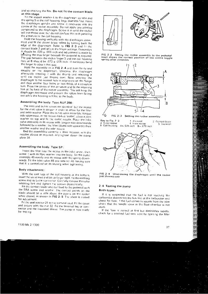
and so s t r a i n i ng t he f l ex . Do no t f i t t he con tac t b l adea t t h i s s t age .
F i t t he impac t washe r 4 t o t he d i aph ragm sp ind le andthe sp r i ng 5 i n t he co i l hous ing , l a rge d i am"e te r i i r s t . I nse r tt he d i aph ragm sp ind le and sc rew i t c l ockw i se i n t o t hecen t re o f t he rocke r assemb ly . Do no t app l y any Jo rn t i ngcompound t o t he d i aph ragm. Sc rew i t i n un t i l t he r ocke rw i l l no t t h row ove r , bu t do no t con fuse t h i s w i t h j ammingthe a rma tu re r n t he co r l hous inq
Ho ld t he hous ing ve r t i ca l l y , , J i t n t nu d i aph ragm uppe r_mos t and f i t t he e l even b rass ro l l e r s by t u rn i ng back t heedge o f t he d i aph ragm. Re fe r t o F IG 2 :3 - d f i t t n "con tac t b l ade 2 and ad lus t t he f i nge r se t t i ngs . D imens ionArshou ld be 035 * 005 i nch and ad lus tme"n t i s made bybdnd rng t he s top f i nge r benea th t he pedes ta l as r equ r red .The gap be tween t he rocke r f i nge r 3 : nd t he co i l hous rngface a t B shou ld be . 070+ 005 i nch I f necessa ry bendthe f i nge r t o ob ta i n t h i s gap .
Ho ld t he assemb ly as i n F IG 2 :4 and push f i rm l y ands tead i l y on t he d i aph ragm. Unsc rew the d i aph ragma l t e rna te l y p ress i ng i t w i t h t he t humb and re l eas rng r tun t i l t he r ocke r l us t t h rows ove r Now unsc rew thed iaph ragm to t he nea res t ho le i n a l i gnmen t on t he f r angeand t hen ano the r f ou r ho les o r two t h i r ds o f a comp le tetu rn . P ress t he cen t re o f t he a rma tu re and f i t t he r e ta rn i ngfo r k a t t he back o f t he rocke r assemb ly . Th i s w i l l keep t hed iaph ragm dep ressed and p reven t t he ro l l e r s f r om fa l l i noou t wh i l e t he hous ing i s f i t t ed t o t he body
Assemb l i ng t he body . Type AUF .200 :The i n l e t and ou t l e t va l ves a re i den t i ca l , bu t t he recess
fo r t he i n l e t va l ve i s deepe r i n o rde r t o a l l ow f o r t he t i l t e rand ex t ra washe r . p i ace t he ou t l e t va l ve assemb ly , t ongues tde uppe rmos t , i n t he recess marked ' ou t l e t , ,
p l ace a l o i n twashe r on t op and f i t t he ou t l e t nozz le . p l ace t he I n l e tvalve assembly in i ts recess wtth tongue s ide downwardsfo l l owed by a washe r , t he f i l t e r ( dome s i de upwards ) t henano lhe r washe r and t he rn l e t nozz le
Bed the assembltes correct ly in their recesses, wi th thenozz tes p l aced as requ i r ed , and t i gh ten down t he c l ampp la te 34
Assemb l i ng t he body . Type Sp :I nse r t t he f i l t e r i n t o t he recess i n t he i n l e t un ion , t hen
sc rew i t w i t h i t s f i b re washe r i n t o t he body . S i t t he ou t l e tassemb ly 45 even l y i n t o i t s r ecess w i t h t he sp r i ng down_wards. Fi t the in let valve 4g and reta iner 46 makr:ng suretha t i t i s cen t ra l i zed on l t s sea t i ng when t i gh ten ing i
Body a t t achmen t :
. With the cast lugs of the coi l housing at the bot tom,
i nse r t t he s i x sc rews and do up f i nge r t i gh i F i t t he ea r t h i ngsc rew and r t s Luca r connec to r Ca re f u l l y r emove t he ro l r e rre ta i n i ng f o r k and t i gh ten t he sc rews d i ame t r i ca l l v
F i t t he con tac t b l ade and co i l l ead t o t he pedes ta l w i t hthe 5BA sc rew and washe r The con tac t po in t s on t heb lade shou ld be a I i t t l e above t he po in t s on t he rocke rwhen c l osed , as shown i n F IG 2 :5 The b l ade i s s l o t t edfo r ad lus tmen t
F i t t he sea l washe r 21 t o t he t e rmrna l s t ud . F i t t he cove rand secu re w i t h t he nu t 32 . F i t t he t e rm ina l t aq o r connector and the insulated s leeve. The pump rs n"ow reaclyf o r t es t i ng .
1 1 0 0 M k 2 1 3 0 0
F I G . 2 : 2 F i t t i n g t h e r o c k e r a s s e m b l y t o t h e p e d e s t a l .
l ! s ! t s n 9 _ w s t h e c o r r e c t p o s i t i o n o f t h e c e n t r e t o g g l e
s p r r n g a t t e r a s s e m b l v
K e y t o F i g 2 ; 3 1 p e d e s t a l3 O u t e r r o c k e r 4 I n n e r r o c k e r6 C o i l h o u s i n g A : 0 3 5 i n c h B : . 0 7 0 i n c h
2 C o n r a c t b l a d e5 T r u n n i o n
F I G 2 : 4 U n s c r e w i n g t h e d i a p h r a g m u n t i l t h e r o c K e rj u s t t h r o w s o v e r
2 : 6 T e s t i n g t h e p u m p
Bo th t ypes :
l f i t i s suspec ted t ha t t he f ue l i s no t r each ing t heca rbu re t t e r d i sconnec t t he f ue l l i ne a t t he ca rbu re t t e r andcheck for { low. l f the fuel comes in squir ts f rom the pipecheck t ha t t he need le va l ve i n t he f l oa t chamber i s no ts tuc k .
l f t he f l ow i s no rma l a t f i r s t bu t d im in i shes rap io r y ,check f o r a b l ocked f ue l t ank ven t by open ing t he f i r r e r
3 l
5 r L 4
F I G 2 : 3 S e t t i n g t n e r o c k e r a s s e m b l v
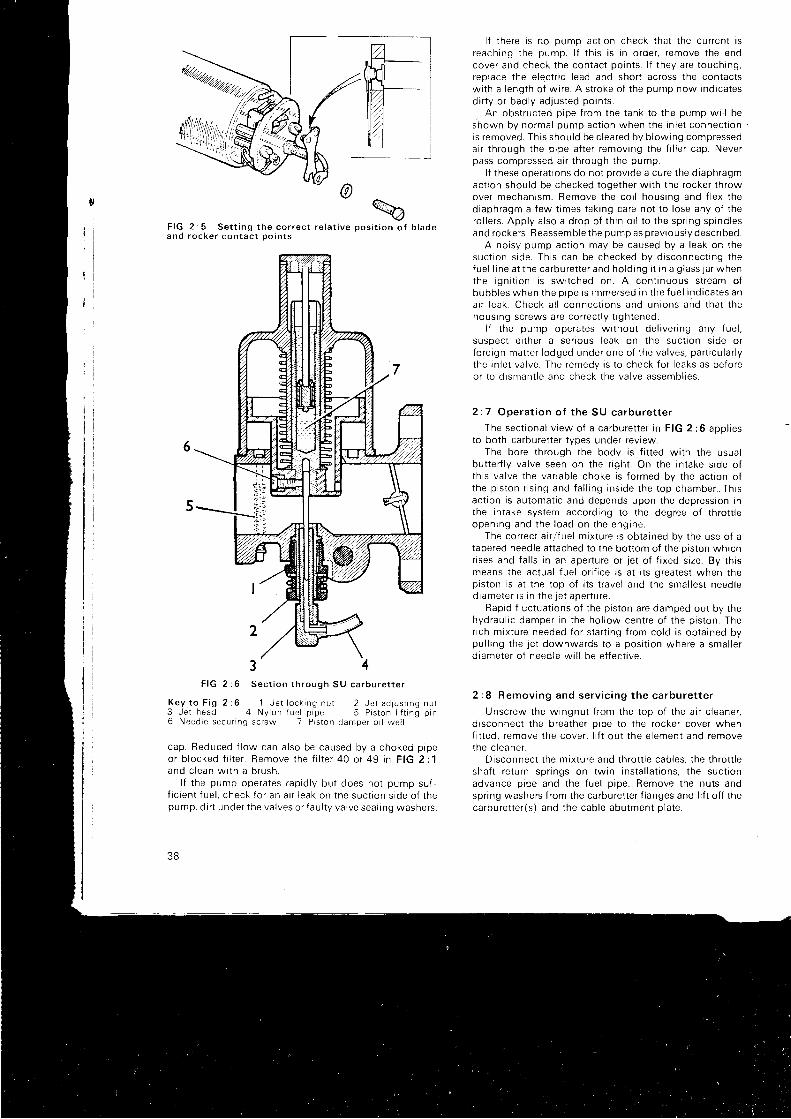
F I G 2 : 5 S e t t i n g t h e c o r r e c t r e l a t i v e p o s i t i o n o f b l a d ea n d r o c k e r c o n t a c t o o i n t s
3 4F IG 2 :6 Sec t i on t h rough SU ca rbu re t t e r
Key t o F i g 2 :6 1 Je t l ock i ng nu t 2 Je t ad jus t i ng nu r3 Je t head 4 Ny lon f ue l p i pe 5 P i s t on i i t t i ng p rn6 Need le secunng sc rew 7 P rs ton damper o i l we l l
cap. Reduced f low can also be caused by a choked prpeo r b l ocked f i l t e r . Remove t he f i l t e r 40 o r 49 i n F IG 2 :1and c l ean w i t h a b rush .
l f t he pump ope ra tes r ap id l y bu t does no t pump su f ,f i c i en t f ue l , check f o r an a r r l eak on t he suc t i on s i de o f t hepump , d i r t unde r t he va l ves o r f au l t y va l ve sea l i ng washe rs .
38
l f there is no DUmo act ion check that the current isreach ing t he pump . l f t h i s i s i n o rde r , r emove t he endcove r and check t he con iac t po in t s . l f t hey a re t ouch ing ,replace the ele,ctr ic lead and short across the contactswi th a length of wire. A stroke of the pump now indicatesd i r t y o r bad l y ad jus ted po in t s .
. An obs t ruc ted p i pe f r om the t ank t o t he pump .w i l l beshown by no rma l pump ac t i on when t he i n l e t connec t i onis removed. This should be c leared by blowing compresseda i r t h rough t he p i pe a f t e r r emov ing t he f i l l e r cap . Neve rpass compressed a i r t h rough t he pump .
l f these operat ions do not provide a cure the diaphragmact ion should be checked together wi th the rocker throwove r mechan i sm. Remove t he co i l hous ing and { l ex t hediaphragm a few t imes taking care not to lose any of thero l l e r s . App l y a l so a d rop o f t h i n o i l t o t he sp r i ng sp ind lesand rockers. Reassemble the pump as previously descr ibed.
A noisy pump act ion may be caused by a leak on thesuc t i on s i de . Th i s can be checked by d i sconnec t i ng t hef ue l l i ne a t t he ca rbu re t t e r and ho ld i ng i t i n a g l ass j a r whenthe i gn i t i on i s sw i t ched on . A con t i nuous s t r eam o fbubb les when t he o i oe i s immersed i n t he f ue l i nd i ca tes ana r r l eak . Check a l l connec t i ons and un ions and t ha t r nehous ing sc rews a re co r rec t l y t i gh tened .
l f t he pump ope ra tes w i t hou t de l i ve r i ng any f ue l ,suspec t e i t he r a se r i ous l eak on t he suc t i on s i de o rf o re i gn ma t t e r l odged unde r one o f t he va l ves , pa r t i cu l a r l ythe in let valve. The remedy is to check for leaks as beforeo r t o d i sman t l e and check t he va l ve assemb l i es .
2 :7 Ope ra t i on o f t he SU ca rbu re t t e r
The sec t i ona l v i ew o f a ca rbu re t t e r i n F IG 2 : 6 app l i esto both carburet ter types under review.
The bore through the body is f i t ted wi th the usualbut ter f ly valve seen on the r ight . On the intake s ide ofth is valve the var iable choke is formed by the act ion oft he p i s t on r i s i ng and f a l l i ng i ns i de t he t op chamber . .Th i sac t i on i s au toma t i c and depends upon t he dep ress ion i nthe intake system according to the degree of throt t leopen ing and t he l oad on t he eng ine .
The correct a i r l fuel mixture is obtained by the use of atapered needle at tached to the bot tom of the piston whichr ises and fa l ls in an aperture or jet of f ixed s ize. By th ismeans the actual fuel or i f rce rs at i ts greatest when thepiston is at the top of i ts t ravel and the smal lest needled iame te r i s i n t he j e t ape r t u re .
Rapid f luctuat ions of the piston are damped out by thehyd rau l i c damper i n t he ho l l ow cen t re o f t he p i s t on . Ther ich mixture needed for star t ing f rom cold is obtained bypu l l i ng t he j e t downwards t o a pos i t i on whe re a sma l l e rdiameter of needle wi l l be ef fect ive.
2 : 8 Remov ing and se rv i c i ng t he ca rbu re t t e r
Unsc rew the w ingnu t f r om the t op o f t he a i r c l eane r ,d isconnect the breather p ipe to the rocker cover whenf i t ted. remove the cover. l i f t out the element and removetne c l eane r .
Disconnect the mixture and throt t le cables, the throt t leshaf t return spr ings on twin insta l lat ions, the suct tonadvance pipe and the fuel p ipe. Remove the nuts andspr ing washers f rom the carburet ter f langes and l i f t of f theca rbu re t t e r ( s ) and t he cab le abu tmen t p l a te .
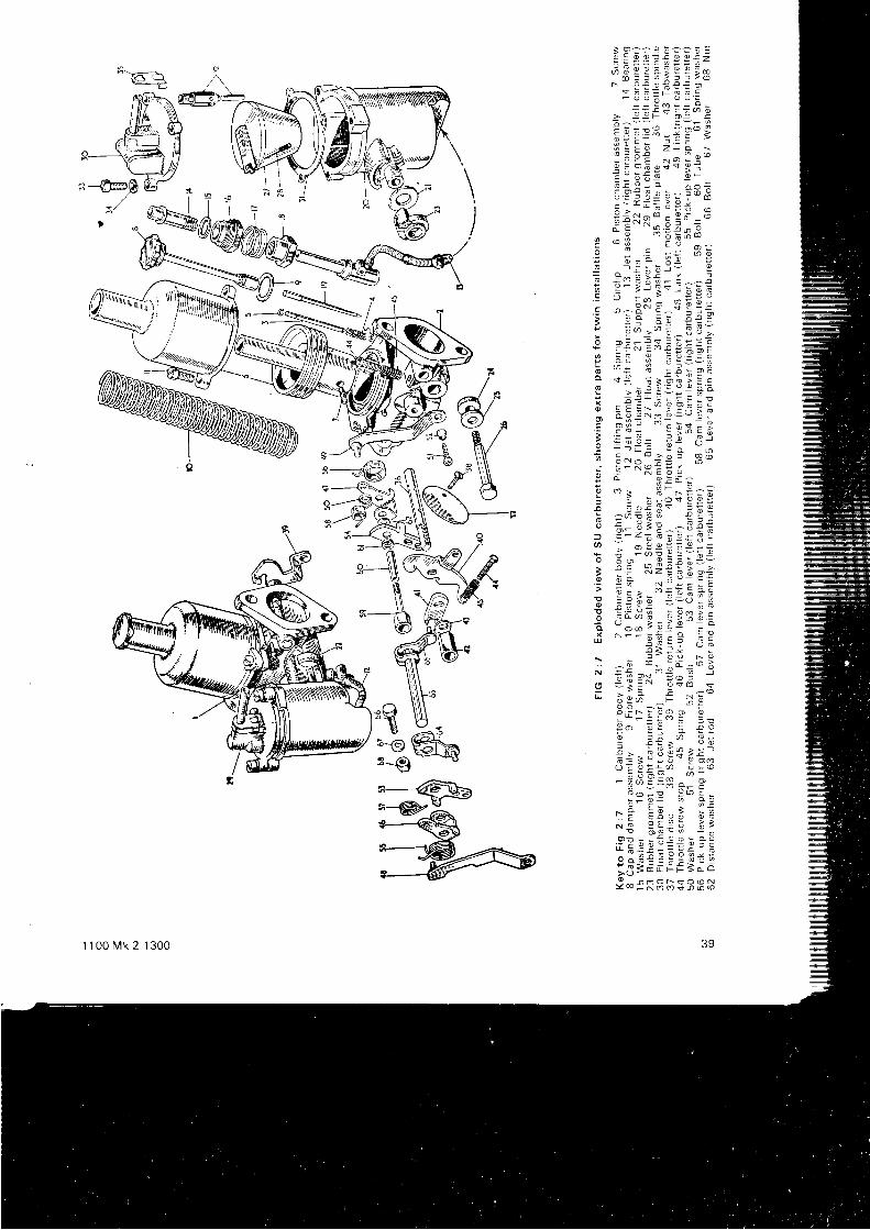
t s ? ? - 9 b ; - b :o ! o o ! ! o o ! ?
; F E E i { E E { ;o t f 6 i t r > @
r o ! o f ! ! o! c G p ! o a L- o o 6 o o =
! ! r - F - g L
; ^ - - . - r ,
E E I : 3 - ; P ' gI = E 9 z - * >' " ; o : ^ - ' o v
n ; i : ; -
E ; 3 i " - : : ={ ? : ! o ; ^ f 6 9l = d i * d E *o > ^ , ; - ; : 9 ?
- ^ E " ' g 9 ; - bF O
= - = 6 6
E g E 3 - , q s - ;; s - i 9 ; - : :t e ; ; j ! + - : ; ; ;. ! c : : - 1 - i i 3. S o a . 4 - i ' - o i i - .: o g ; o ! ' ! =- E - z - E ^ S U >
: 3€ 'g*€!e=g€o
- ' ; a : ! : o eg s : t > o a > = co l : o 6 - o g 6 . 0- ; ! u O - ! t r !5 s E F - ' 9 3 , T g E* o Q i N o 9 - - o ,
i E : x - : : d = 3P = ; ; e e E " -7 f i - ^ - ; o : 9 @
. ! - X o € ; -
; ! u ,
E - . H * - 9 : F= 6 b : o $ 9 9 i3 - 9 ^ r a ; - ? 6 96 - ' ' : a - : r xo = - - U i E ^ : U € E? 5 - ' H : ! 9 * 3 :I ; 3 6 i E g = * !o i ? , ^ 3 : ; d = -I ; : ; : = t ! _ d p i; ; r _ s J ; c i E
- - : 5 - o : - ! Y d o
E : : 9 9 = - U ; HE ! r : - ? 7 : o o ! -9 , ' ! * " ' S - Y i n g =o - o o > 9 9 =
- - -x N - - : ; - o : :
E a : l - :r i P - ? , 2 h 9i s ; . * ; : I i - ' jo = - E ! ' E + r x
X : - ' 6 ;! , : r - . ' o o o o
: ! ' : > o o: : d i o > - -! > t Y o y * > t. i ; l i : . , : - , 9 " t :u F Y c ' ^ " ' - : : -- # 6 5 : S s - P- o : ! ! 0 1 :
- l E E . . r ; i- ! ! E : ! ; ;O - , - l @ o - O O
; I p B ; E E ; i Eo o 3 € i i : ; t i E* . 3 = ; - i F S i r o
9 . 3 R B D $ 3 3 3
'g u,:€%n--*r
:%R@
-)q
s-SmO
44 /d\A/\Y/ €
391 1 0 0 M k 2 1 3 0 0
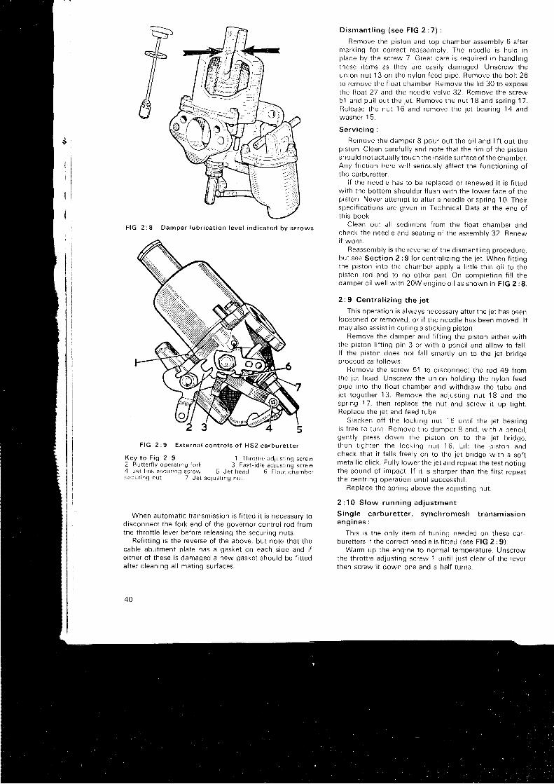
F I G 2 : 8 D a m p e r l u b r i c a t i o n l e v e l i n d i c a t e d b v a r r o w s
D i s m a n t l i n g ( s e e F I G 2 : 7 ) :
Remove the piston and top chamber assembly 6 af termark i ng {o r co r rec t r eassemb ly . The need le i s he ld t np lace by t he sc rew 7 . G rea t ca re i s r equ i r ed i n hand l i ngthese i t ems as t hey a re eas i l y damaged . Unsc rew theun ion nu t 13 on t he ny l on f eed p i pe . Remove t he bo l t 26to remove the f loat chember. Remove the l id 30 to exposethe f loat 2-7 and the needle valve 32. Remove the screw51 and pu l l ou t t he j e t . Remove t he nu t 1 8 and sp r i ng 1 7 .Re lease t he nu t 16 and remove t he j e t bea r i ng 14 andwashe r 1 5 .
Se rv i c i ng :
Remove t he damper 8 pou r ou t t he o i l and l i f t ou t t hep i s t on . C lean ca re fu l l y and no te t ha t t he r im o f t he p i s t onshou ld no t ac tua l l y t ouch t he i ns i de su r f ace o f t he chamber .Any f r i c t i on he re w i l l se r i ous l y a f f ec t t he f unc t i on i ng o fthe carburet ter .
i f the needle has to be replaced or renewed i t is f i t tedw i t h t he bo t t om shou lde r f l u sh w i t h t he l owe r f ace o f t hep i s t on . Neve r a t t emp t t o a l t e r a need le o r sp r i ng 10 . The i rspec i f i ca t i ons a re g i ven i n Techn i ca l Da ta a t t he end o ft h i s book .
C lean ou t a l l sed imen t f r om the f l oa t chamber anocheck t he need le and sea t i ng o f t he assemb ly 32 . Renewi f wo rn
Reassemb ly i s t he reve rse o f t he d i sman t l i ng p rocedu re ,bu t see Sec t i on 2 :9 f o r cen t ra l i z i ng t he j e t . When f i t t i ngthe p i s t on i n t o t he chamber app l y a l i t t l e t h i n o i l t o t hep i s t on rod and t o no o the r pa r t . On comp le t i on f i l l t hedamper o i l we l l w i t h 20W eng ine o i l as shown i n F IG 2 : 8 .
2 : 9 C e n t r a l i z i n g t h e j e t
This operat ion is a lways necessary af ter the jet has beenloosened o r r emoved , o r i f t he need le has been moved . l tmay a l so ass i s t i n cu r i ng a s t i c k i ng p i s t on .
Remove t he damper and l i f t i ng t he p i s t on e i t he r w i t hthe p i s t on l i f t i ng p i n 3 o r w i t h a penc i l and a l l ow t o f a l l .l { the piston does not fa l l smart ly on to the jet br iogep roceed as f o l l ows :
Remove the screw 51 to d isconnect the rod 49 f romthe j e t head . Unsc rew the un ion ho ld i ng t he ny l on f eedp ipe i n t o t he f l oa t chamber and w i t hd raw the t ube andje t t oge the r 13 . Remove t he ad jus t i ng nu t 1B and t hesp r i ng 17 , t hen rep lace t he nu t and sc rew i t up t i gh t .Rep lace t he j e t and f eed t ube .
S lacken o t f t he l ock tng nu t 16 un t i l t he Je t bea r i ngi s f r ee t o t u rn . Remove t i r e damper 8 and , w i t h a penc i l ,gen t l y p ress down t he p i s t on on t o t he j e t b r i dge ,t hen t i gh ten t he l ock i ng nu t ' 1
6 . L i f t t he p i s t on andcheck that i t fa l ls f reely on to the jet br idge wi th a sof tme ta l l i c c l i c k . Fu l l y l owe r t he j e t and repea t t he t es t no t i ngthe sound o f impac t . l f i t i s sha rpe r t han t he f i r s t r epea tt he cen t r i ng ope ra t i on un t i l success fu l .
Rep lace t he sp r i ng above t he ad jus t i ng nu t .
2 : 1 0 S l o w - r u n n i n g a d j u s t m e n t
S ing le ca rbu re t t e r . s ynch romesh t r ansm iss i one n g i n e s :
Th i s i s t he on l y i t em o f t un i ng needed on t hese ca rbu re t t e r s i f t he co r rec t need le i s f i t t ed ( see F IG 2 :9 ) .
Warm up t he eng ine t o no rma l t empe ra tu re . Unsc rewthe throt t le ad. lust ing screw 1 unt i l just c lear of the levert hen sc rew a t down one and a ha l f t u rns .
F I G 2 ; 9 E x t e r n a l c o n t r o l s o f H S 2 c a r b u r e t t e r
K e y t o F i g 2 : 9 1 T h r o t t l e a d j u s t i n g s c r e w2 B u t t e r i l y o p e r a t i n g { o r k 3 F a s t - i d l e a d l u s t i n g s c r e w4 J e t l i n k s e c u n n g s c f e w 5 J e t h e a d 6 F l o a l c h a m b e rs e c u r l n g n u 1 7 J e t a d l u s t r n g n u t
When automat ic t ransmissron is f i t ted i t is necessary todisconnect the fork end of the governor contro l rod f romthe throt t le lever before re leasing the secur ing nuts.
Ref i t t ing is the reverse of the above, but note that thecab le abu tmen t p l a te has a gaske t on each s i de and i fe i ther of these is damaged a new gasket should be f i t teda f t e r c l ean ing a l l ma t i ng su r f aces .
40
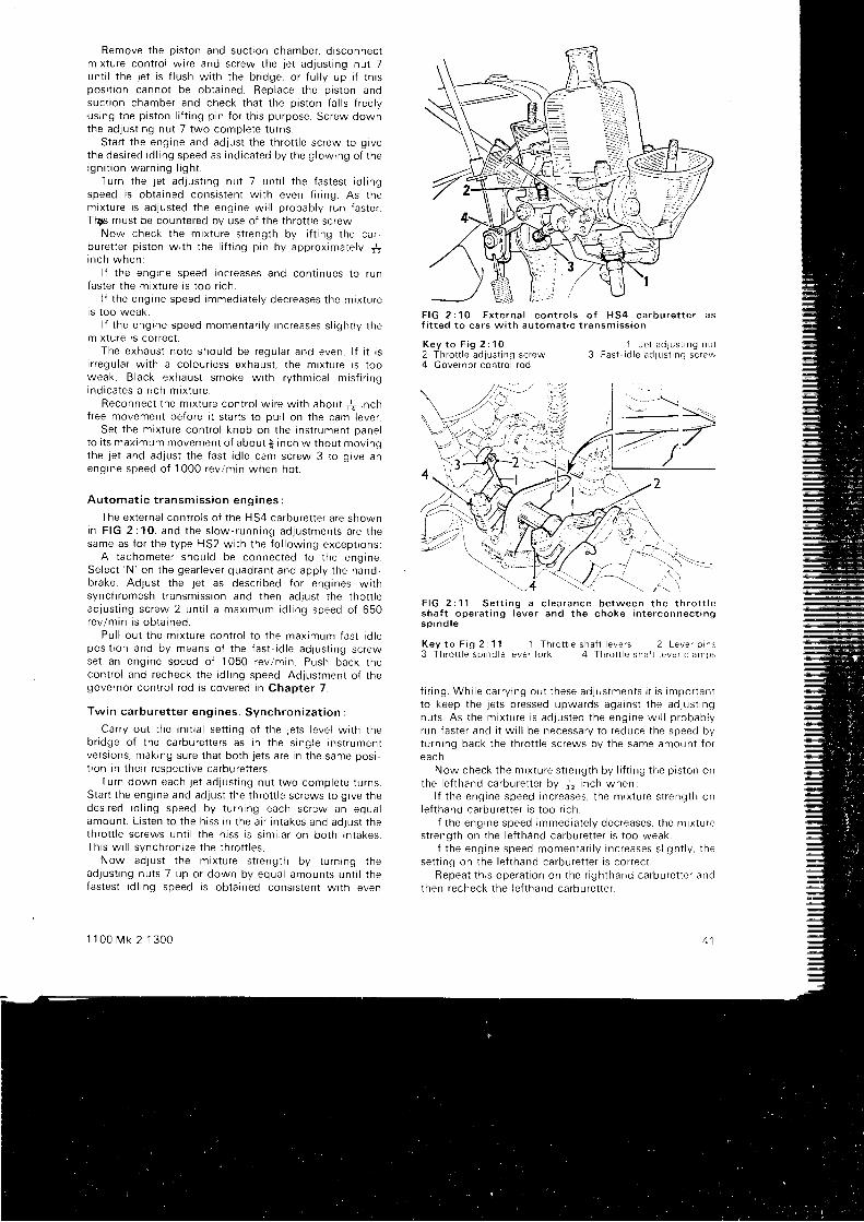
Remove t he p i s t on and suc t i on chamber , d i sconnec tm ix tu re con t ro l w i r e and sc rew the j e t ad jus t i ng nu t 7un t i l t he j e t i s f l u sh w i t h t he b r i dge , o r f u l l y up i f t h i spos i t i on canno t be ob ta i ned . Rep lace t he p i s t on andsuct ion chamber and check that the piston fa l ls f reelyus rng t he p i s t on l i f t i ng p i n f o r t h i s pu rpose . Sc rew downthe ad jus t i ng nu t 7 two comp le te t u rns .
Star t the engine and adlust the throt t le screw to g ivethe des i r ed i d l i ng speed as i nd i ca ted by t he g l ow ing o f t hei gn i t i on wa rn ing l i gh t .
Tu rn t he j e t ad jus t i ng nu t 7 un t i l t he f as tes t i d l i ngspeed is obtained consistent wi th even f i r ing. As them ix tu re i s ad jus ted t he eng ine w i l l p robab l y r un f as te r .Tios must be countered bv use of the throt t le screw.
Now check t he m ix tu re s t r eng th by l i f t i ng t he ca r -bu re t t e r p i s t on w r th t he l i f t i ng p i n by app rox ima te l y +i n c h w h e n :
l f t he eng ine speed rnc reases and con t i nues t o r unfaster the mixture is too r ich.
l f t he eng ine speed immed ia te l y dec reases t he m ix tu rei s t oo weak .
l f t he eng ine speed momen ta r i l y i nc reases s l i gh t l y t hemrxture ts correcl
The exhaus t no te shou ld be regu la r and even . l f i t t si r r egu la r w r t h a co lou r l ess exhaus t , t he m ix tu re i s t ooweak . B lack exhaus t smoke w i t h r y t hm ica l m i s f i r i ngi nd i ca tes a r i ch m i x tu re .
Reconnec t t he m ix tu re con t ro l w i r e w i t h abou t { i n ch{ree movement before i t s tar ls to pul l on the cam lever.
Se t t he m ix tu re con t ro l knob on t he i ns t r umen t Dane lt o i t s max imum movemen t o f abou t $ i nch w i t hou t mov ingthe . let and adjust the fast- id le cam screw 3 to g ive aneng ine speed o f 1000 rev lm in when ho t .
Au toma t i c t r ansm iss i on eng ines :
The external contro ls of the H54 carburet ter are shownin F IG 2 : 10 , and t he s l ow- runn ing ad jus tmen ts a re t hesame as f o r t he t ype H52 w i t h t he f o l l ow ing excep t i ons :
A t achome te r shou ld be connec ted t o t he eng tne .Se lec t 'N ' on t he gea r l eve r quad ran t and app l y t he hand -brake. Adjust the jet as descr ibed for engines wi thsynch romesh t r ansm iss i on and t hen ad jus t t he t ho t t l eadJus t i ng sc rew 2 un t i l a max imum i d l i ng speed o f 650rev lm in i s ob ta i ned .
Pu l l ou t t he m ix tu re con t ro l t o t he max imum fas t i d l epos i t i on and by means o f t he f as t - i d l e ad jus t i ng sc rewse t an eng ine speed o f 1050 rev /m in . Push back t hecon t ro l and recheck t he i d l i ng speed . Ad jus tmen t o f t hegovernor contro l rod is covered in Chapter 7.
Tw in ca rbu re t t e r eng ines . Synch ron i za t i on :
Ca r r y ou t t he i n i t i a l se t t i ng o f t he l e t s l eve l w i t h t heb r i dge o f t he ca rbu re t t e r s as i n t he s i ng le i ns t r umen tve rsaons , mak ing su re t ha t bo th j e t s a re i n t he same pos i -t ion in their respect ive carburet ters.
Tu rn down each j e t ad jus t i ng nu t two comp le te t u rns .Star t the engine and adjust the throt t le screws to g ive thedes i r ed i d l i ng speed by t u rn i ng each sc rew an equa lamoun t . L r s ten t o t he h i ss i n t he a i r i n t akes and ad jus t t heth ro t t l e sc rews un t i l t he h i ss i s s rm i l a r on bo th i n t akes .Th i s w i l l s ynch ron i ze t he t h ro t t l es .
Now ad . j us t t he m ix tu re s t r eng th by t u rn i ng t head jus t i ng nu t s 7 up o r down by equa l amoun ts un t i l t hefastest id l ing speed is obtained consistent wi th even
1 1 0 0 M k 2 1 3 0 0
F I G 2 : 1 0 E x t e r n a l c o n t r o l s o f H S 4 c a r b u r e t t e r a sf i t t e d t o c a r s w i t h a u t o m a t i c t r a n s m i s s i o n
K e y t o F i g 2 : 1 02 T h r o t t l e a d j u s l i n g s c r e w4 Governor cont ro l rod
1 J e t a d l u s t i n g n u l3 F a s t ' i d l e a d J U S t i n g s c r e w
F I G 2 : 1 1 S e t t i n g a c l e a r a n c e b e t w e e n t h e t h r o t t l esha f t ope ra t i ng l eve r and t he choke i n t e r connec t i ngs p i n d l e
Key t o F i g 2 : 1 1 1 Th ro t t l e sha f t l e ve rs 2 Leve r p rns3 Th ro t t l e sp i nd le l eve r f o r k 4 Th ro t t l e sha f t l e ve r c l an rps
f i r i ng . Wh i l e ca r r y i ng ou t t hese ad jus tmen ts i t i s impo r tan tto keep the Jets pressed upwards against the adlust ingnu t s . As t he m ix tu re i s ad jus ted t he eng ine w i l l p robab l yrun faster and i t wi l l be necessary to reduce the speed byturning back the throt t le screws by the same amount fore a c h .
Now check t he m ix tu re s t r eng th by l i f t i ng t he p i s t on onthe l e f t hand ca rbu re t t e r by Ja i nch when :
l f t he eng ine speed rnc reases , t he m ix tu re s t r eng th onle f t hand ca rbu re t t e r i s t oo r r ch .
l f t he eng ine speed immed ia te l y dec reases , t he m ix tu restrength on the lef thand carburet ter is too weak.
l f t he eng ine speed momen ta r i l y i nc reases s l i gh t l y , t hese t t i ng on t he l e f t hand ca rbu re t t e r i s co r rec t
Repea t t h i s ope ra t i on on t he r i gh thand ca rbu re t t e r andthen recheck t he l e f t hand ca rbu re t t e r .
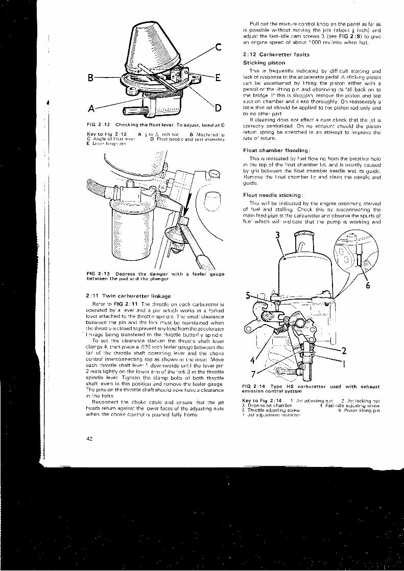
DA
F I G 2 : 1 3 O e p r e s s t h e d a m p e r w i t hb e t w e e n t h e p a d a n d t h e p l u n g e r
\\\l..li\a f e e l e r g a u g e
2 : 11 Tw in ca rbu re t t e r l i n kage
Re fe r t o F IG 2 : 1 1 . The t h ro t t l e on each ca rbu re t t e r i soperated by a lever and a pin which works in a forkedleve r a t t ached t o t he t h ro t t l e sp i nd le . The sma l l c l ea rancebe tween t he p i n and t he f o r k mus t be ma in ta i ned whenthe throt t le is c losed to prevent any load f rom the acceleratorl inkage being t ransfered to the rhrot t le but ter f ly spindle.
To set th is c learance s lacken the throt t le shaf t leverc lamps 4. then place a .070 inch feeler gauge between thetai l of the throt t le shaf t operat ing lever and the chokecontrol interconnect ing rod as shown in the inset . Moveeach throt t le shaf t lever
'1 downwards unt i l the lever orn
2 rests l ight ly on the lower arm of the fork 3 in the throt t lesp ind le l eve r . T i gh ten t he c l amp bo l t s o f bo th t h ro t t l eshaf t levers in th is posi t ion and remove the feeler gauge.The pins on the throt t le shaf t should now have a c learancein t he f o r ks .
Reconnec t t he choke cab le and ensu re t ha t t he j e theads return against the lower faces of the adjust ing nutswhen t he choke con t ro l r s oushed f u l l v home .
42
Pul l out the mixture contro l knob on the panel as far asi s poss ib l e w i t hou t mov ing t he j e t s ( abou t f i n ch ) andad ;us t t he f as t - r d l e cam sc rews 3 ( see F IG 2 :9 ) t o g i vean eng ine speed o f abou t 1000 rev /m in when ho t .
2 : 12 Carburet ter faul ts
S t i c k i ng p i s t on
Th i s i s f r equen t l y i nd i ca ted by d i f f i cu l t s t a r t i ng andlack of response to the accelerator pedal . A st ick ing pistoncan be ascerta ined by l i f t ing the pjston ei ther wi th apenc i l o r t he I i i t i ng p i n and obse rv i ng i t s i a l l back on t othe br idge. l f th is is s luggish, remove the piston and topsuc t i on chamber and c l ean t ho rough l y . On reassemb ly al i t t l e t h i n o i l shou ld be app l i ed t o t he p i s t on rod on l y andto no other part .
l f c leaning does not ef fect a cure check that the jet isco r rec t l y cen t ra l i zed . On no accoun t shou ld t he p i s t onreturn spr ing be stretched in an at tempt to improve therate of return.
F l oa t chamber f l ood ing
This is indicated by f uel f lowing f rom the breather hotei n t he t op o f t he f l oa t chamber l i d , and i s usua l l y causedby gr i t between the f loat chamber needle and i ts guide.Remove t he f l oa t chamber l i d and c l ean t he need le andg u r de .
F loa t need le s t i c k i ng :
Th i s w i l l be i nd i ca ted by t he eng ine becom ing s ta r vedo f f ue l and s ta l l i ng . Check t h i s by d i sconnec t i ng t hemain feed pipe at the carburet ter and observe the spurts off ue l wh i ch w i l l i nd i ca te t ha t t he pump i s wo rk i ng and
F I G 2 : 1 4 T y p e H S c a r b u r e t t e r u s e d w i t h e x h a u s te m i s s i o n c o n t r o l s y s t e m
K e y t o F i g 2 : 1 4 1 J e t a d j u s t i n g n u t 2 J e t l o c k i n g n u r3 Depress ion chamber 4 Fas t - id le ad jus t ing screw5 Thro t t le ad jus t ing screw 6 P is ton l i f t ing p in7 Je t ad jus lment res t r i c to r
F I G 2 : 1 2 C h e c k i n g t h e f l o a t l e v e r . T o a d j u s t . b e n d a t C
K e y t o F i g 2 : 1 2 A ; l o f t r I n c h b a r B M a c h i n e d t i pC A n g l e o f f l o a t l e v e r D F l o a t n e e d l e a n d s e a t a s s e m o r yE L e v e r h i n g e p i n
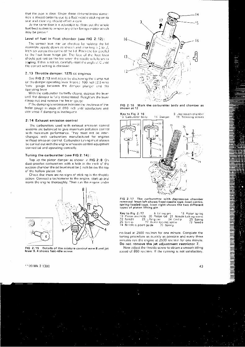
t ha t t he o iDe i s c l ea r . t Jnde r t hese c i r cums tances s ta r va -t i on i s a lmos t ce r t a i n l y due t o a f l oa t need le s t i c k i ng on i t ssea t and c l ean ing shou ld e f f ec t a cu re
A t t he same t ime i t r s adv i sab le t o c l ean ou t t he who lef ue l f eed svs tem to r emove any o the r f o re i gn ma t t e r wh i chmav be o resen t
L e v e l o f f u e l i n f l o a t c h a m b e r ( s e e F I G 2 : 1 2 ) :
The co r rec t l eve l can be checked bv ho ld rnq t he r r oassemb ly ups ide down as sho , rn and I nse r t t ng a ; t o i ' 16i nch ba r ac ross t he cen t re o f t he I d P lace i he ba r pa ra l l e lt o t he f l oa t l eve r h i nge p i n . The f ace o f t he f l oa t l eve rshou ld j us t r es t on t he ba r when t he need le i s f u l l y on i t sse i t i ng . l f t h i s i s no t so , ca re fu l l y f ese t t he ang le a t C un t i lt he co r rec t se t t i ng i s ob ta rned .
2 : 1 3 T h r o t t l e d a m p e r . 1 2 7 5 c c e n g i n e s
S e e F f G 2 : 1 3 a n d a d l u s t b y s l a c k e n i n g t h e c l a m p n u to n t h e d a m p e r o p e r a t i n g l e v e r l n s e r t a 1 0 0 i n c h ( 2 . 5 m m )fee le r gauge be tween t he dan rpe r p l unge r and t heope ra t rng l eve r .
W i t h t he ca rbu re t t e r bu t t e r f l y c l osed , dep ress t he l eve run t i l t he damper i s f u l l y compressed . Re t i gh ten t he l eve rc l amp nu t and remove t he f ee le r gauge .
l f t he damp ing i s excess i ve i nc rease t he t h r ckness o f t hefee le r gauge i n s t eps o f . 010 i nch un t i l sa t i s f ac to r y andv i ce ve rsa i f damp ing i s i nadequa te
2 : 1 4 E x h a u s t e m i s s i o n c o n t r o l
The carburet ters used wi th exhaust emission contro lsys tems a re ba lanced t o g i ve max imum po l l u t i on con t ro lw i t h max imum pe r f o rmance . They mus t no t be i n t e r -changed w i t h ca rbu re t t e r s manu fac tu red f o r eng inesw i t hou t em iss ron con t ro l . Ca rbu re t t e r t un i ng mus t a lwaysbe ca r r i ed ou t w i t h t he eng ine em iss i on con t ro l equ ipmen tconnec ted and ope ra t i ng co r rec t l y .
Tun ing t he ca rbu re t t e r ( see F IG 2 : 1 4 ) :
Top up t he p i s t on damper as shown i n F IG 2 :8 . Ondus t -p roo fed ca rbu re t t e r s w i t h a ho le i n t he neck o f t hesuc t i on chamber t he o i l l e ve l mus t be i i n ch be low t he t opof the hol low oiston rod.
Check t ha t t he re a re no s i gns o f s t i c k i ng i n t he t h ro t t l eac t i on . Connec t a t achome te r t o t he eng ine , s t a r t up andwarm the eng ine t ho rough l y . Then run t he eng ine unde r
1 5 D e t a i l s o f t h e m i x t u r e c o n t r o l w i r e 8 a n d i e t4 s h o w s f a s t - i d l e s c r e w
1 1 0 0 M k 2 1 3 0 0
F I G 2 : 1 6 M a r k t h e c a r b u r e t t e r b o d v a n d c h a m b e r a ss h o w n a t 1 2
l-- r- -; l--l r-;
lffi,itffilBEI
l 4
t q
l6-________
K e y t o F i g 2 : 1 61 3 C a r b u r e t t e r b o C y
l 7
I
\__ .
3 D e p r e s s r o n c h a m b e f1 4 D a m p e r 1 6 R e t a i n r r r g s c r e w s
F I G 2 :lever 9
F I G 2 : 1 7 T h e c a r b u r e t t e r w i t h d e p r e s s i o n c h a m b e rr e m o v e d . I n s e t l e f t s h o w s f i x e d n e e d l e t y p e . I n s e t c e n t r e ,s p r i n g - l o a d e d t y p e . I n s e t r i g h t s h o w s t h e t w o d i f f e r e n tt y p e s o f p i s t o n l i f t i n g p i n
K e y t o F i g 2 : 1 7 6 L i f t r n g p r n 1 8 P i s r o n s p r i n g1 9 P i s t o n a s s e m b l y 2 0 P r s t o n r o d 2 1 N e e d i e l o c k i n g s c r e w2 2 N e e d l e 2 3 L i f t i n g p i n 2 4 C r c l i p 2 5 S p r r n g26 C i rc l ip 72 Gu ide lock ing screw 73 Need le7 4 N e e d l e s u p p o r r g u i d e 7 5 S p r i n g
n o - l o a d a t 2 5 0 0 r e v / m i n f o r o n e m i n u t e . C o m p l e t e t h et u n i n g p r o c e d u r e a s q u i c k l y a s p o s s i b l e a n d e v e r y t h r e em i n u t e s r u n t h e e n g i n e a t 2 5 0 0 r e v / m i n f o r o n e m i n u t e .Do no t remove the je t ad jus tment res t r i c to r 7 .
Now ad lus t the th ro t t le sc rew to ob ta in a smooth id l ing
speed o f 850 rev /min . l f the runnrng is no t sa t is fac to ry ,
43
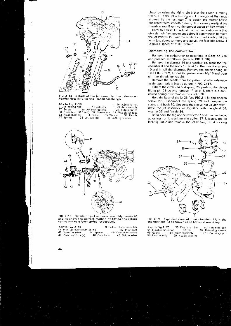
I I - ; l
l-il,:'
F I G 2 : 1 8 D e t a i l s o f t h e j e t a s s e m b l y . I n s e t s h o w s j e tbear ing de ta i l s fo r spr ing- ioaded need ie type
K e y t o F i g 2 : 1 8 1 J e t a d j u s t i n g n u t2 Je t lock ing nu t 7 Rest r i c to r 26 Je t assJmory2 7 S c r e w 2 8 J e t p i c k u p l i n k 2 9 R e t u r n s p r r n g30 Brass bush ( i f f ined) 31 S leeve nur 32 F tex ib le je r rub ;33 F loa t chamber 34 Gland 35 Washer 36 Fer rure37 Spr ing 38 Je t bear ing 39 Lock ing washer
F I G 2 : 1 9 D e t a i l s o f p i c k - u p i e v e r a s s e m b l y . I n s e t s 4 0and 45 show the cor rec t method o f f i t t ing the re tu rnspr ing and cam lever spr ing respec t ive ly
K e y t o F i g 2 : 1 9 9 P i c k - u p l e v e r a s s e m b l y41 Prck 'up lever re tu rn spr ing 42 P ivo t bo l t43 Spnng washer 44 Spacer 46 Cam lever spr ing47 P ivo t bo l t tube(s ) 48 Cam lever 49 Sk id washer
44
check by using the l i f t ing pin 6 that the piston is fa l l ingfreely. Turn the jet adjust ing nut 1 throughout the rangeal lowed by the restr ic tof 7 to obtain the fastest soeedconsistent wi th smooth running. l f necessary readjust thethrot t le screw 5 to g ive the correct speed of 850 rev/mln.
Refer to FIG 2 :15. Adjust the mrxture coniro l wire 8 togive 1f inch f ree movement before i t commences to movethe jet lever 9. Pul l out the mixture contro l knob unt i l thejet is just about to move and adjust the fast- id le screw 4to g i ve a speed o f 1100 rev lm in .
D i sman t l i ng t he ca rbu re t t e r :
Remove the carburet ter as descr ibed in Sect ion 2:8and p roceed as f o l l ows : ( r e fe r t o F IG 2 : 16 ) .
Remove t he damper 14 and washe r ' 1 5 , ma rk t he t opchamber 3 and the body 1 3 as at 1 2. Remove the screws16 and l i f t of f the chamber. Remove the piston spr ing 18(see FIG 2:17), l i t ' t . out the piston assembly 19 and pouroi l f rom the piston rod 20.
Remove the needle f rom the piston rod af ter referenceto t he app rop r i a te i nse t d i ag ram i n F IG 2 :17 .
Extract the c i rc l ip 24 and spr ing 25, push up the pistonl i f t ing pin 23 up and remove. l f , as at 6, there is a con-cealed spr ing, f i rs t remove the c i rc l ip 26.
Ho ld t he base o f t he 1e t 26 ( see F IG 2 :18 ) and s l ackenscrew 27. Disconnect the spr ing 29 and remove thescrew and bush 30. Unscrew the s leeve nut 31 and wi th-draw the jet assembly 26 together wi th the gland 34,washe r 35 and f e r ru l e 36 .
Bend back the tag on the restr ic tor 7 and remove the jetadjust ing nut 1, restr ic tor and spnng 37. Unscrew the jetlocking nut 2 and remove the jet bear ing 38. A locking
57i-_\
552
s8_ll -59
56
5 lF I G 2 : 2 0 E x p l o d e d v i e w o f f l o a t c h a m b e r . M a r k t h ec h a m b e r a n d l i d a s s h o w n a t 5 2 b e f o r e d i s m a n t l i n g
K e y t o F i g 2 : 2 0 3 3 F l o a t c h a m b e r 5 0 R e t a i n i n q b o l t5 1 F l e x i b l e m o u n t i n g 5 3 L r d 5 4 R e t a i n i n q s i r e w s5 5 G a s k e t 5 6 F l o a t a s s e m b l y 5 7 F t o a r h - i n g e p r n58 F loa t need le 59 Need le seat inq
4342

9n
uaql ' l le+ ol sur6aq ]snI paods out6ua aLl ] l r ]un 's ln]xtu l
eql 6uruoleaM 'AlMols ur l r Moj3s uor l l 'poutelqo st peadsaurOue lsalsel aql l r lun ! lnu 6ur isnfpe ]at aql u lnt MoN
'reDarnqrBc oq] 6urunf rapunuor lsas srq] ur raruee peqr jssap ernpocold oql lno Ai leJ
' suo l ]
-snr lsur s larnlcelnueur aql L l l r /v \ aSueploScp ut las^ leugse6 lsneqxa oql lcauuoC ebels srr | l le ! lnu 6ur lsntpelot oql qcnol 1ou o6 uado urnl l ln l auo t t les uoq] 'pasolc
sr e luoJql aq] uaqM dols s]r lo realc lsnI Matcs 6ur lsnlpeal l lorq l eq] Marcsun urec aql jo realc Malcs alpt- lse]eql MaJssun pue erM lor luo3 aln lxrut aqt ]cauuocstc
: 6urunl . te l la lnqlec ala ldt 'uoC
:sMol lo ' se leuelnqlPc eqleunl pue osor l taqueqc uorssetdap aq] ]cauuooau g:Zuor lces ur paqi lcsap se touetnqlBs eq] l t lou s le l+ ueel l |q l
M O I J E
Aq ps lec tpur se Apoq le l le lnq lec oq l seqcno l 6e1 ;ec l1 teneq l f l l un ro lcu lsor luour lsn lpe oq t u ln l tZ :Z g l )
JOls ! r l sa j eq l l co l pue uMop le l ] auo lnu urn l l le ] o lsue ls l sn I posds l ! lun lnu eq ] u r marcs uoq] poads eu !6uelse lse l u le lqo o l lnu Eur lsn lpe ta f oq l u tn l ZZ:Z g- lJ
slvlj-lnN 9Nr$nr0v llf
I
l . ' .*HJIU I ) lV3M
l tdulNtcNl
'l'lvr oI9N|SNSVIWOC ISnr
rg3H uotCtulslu or3ds tNtgf.,t3I3f L3S
000 I z ly \ t 00i l
ure ro^a ' l 89 lnu e lpurds lg raqseMqel 99o lpurds a l l to rq l 99 sMarcs t9 a^ le^ l ru r - l tga0ue11 ra r la rnqre3 69 csrp a l l lo r r . l1 17 :7 611 o1 Aey
09 le uMor ls se 3srp puea 6 u e f l a q ] I r e W A l q u o s s e a l l l o r r l l ] o s l l e l o o L Z : Z g _ l J
Marcsun ueql 'abpuq lat le lnqlec aql q l tM qsn; l sr 1eloql jo do] aq] l r lun lnu 6ur lsnlpe la l aq] ur Molcs olpaaupapeol-6urrds e ql l r* Aressacau ]ou st stq l '6 :
Z uor loasu l pa lon r l su r se 1e l eq l az t l e l l uaO ZL tZ g l J u r uMoqs sepr l eqr puP ra^al leol l aql uaaMlaq e3ueleolc aqi l3€q3'autbuo aqt 6urce1 anlen aql jo peaqaql q i rM elpurds aq] Moloq eq lsnr ! o^ len t ru l t l a l l lo lq]eql sMai3s aq1 6urualq6l l etoreq oloq oql ut cstp o luorqloql azr ler luaS pesol3 st o l l lo jq l eql uaqM spleMlnoasel p lnoqs t9 sMaics lunstelunoc oql ]o speeq aql
:s lurod 6urano; lo l oqt 6ut lou'suor lcnr lsur 6ur l lueusrp aql ]o aslenat aql st srq j
: AlqulasseaU
'A rp o l ^ ^o l l e pue ] u rdsur sued l ls uealo alpurds ol l lorq] eq] uo Aeld pue reoMalrssa3xa rol lcaq3 sluauodlr,roc tcadsns i{ue nnauatpue a6euep ro ieaM io] l l ln la lec fuan syed l le lcadsul/9 rnu aqt Mercsun pup gg laqseMqe] aq] osealau gg
alpurds aqr ut lo ls s l t u lo j ] cstp aq] ^^eipql tM pup aluol l ]aql uado ' tg sMarcs oM] aql a^oureu ' LZi Z glJ ut 0g leuntoqs se aouel ] pue cstp aql ) teu pue al l lorqt oql asolC
p t laql uror ] our lpas oql M€losun Bg elpaau pue gg leol l aq]onouei pue 1g urd a6urq teol ] aql lno qsnd gg Alquesse]eol ] pue gg le)se6'pr l aq] go Ur l pue sMaios aql a^oulalueq] 'AlquJasseer io i pr l pue raqueqo ]eol j oqr l rpt
lg DUrlunoulelqrxal l pue t t roqurPqc leol+ eql enourar pue (02: z g l laos) 09 l loq aq] Marcsun 6t raqseM pue 8t ro^al ueceq] e^oureu gg 6uuds pue I t oqnl l loq ]o^td aql ]no l lnd'gy 6urrds uJnlar aq] q l r / l^ 6 i lquasse ra^€l aql anouier puB
Zt Uoq aql Marosun Ot lasur aql ur ! t 6uuds urnle l rene;aq ] t o uo r } l sod eq t € l ou pug '6 ! :Z 9 l J Apn i s A lquossera^el dn- lcrd aql a l lueuisrp og
.6urcuauuoo aJolag
'Aluo srausrnqiec alpaaupaxr l uo a6uel i buueaq aq] rapun pouU s! 6E laqseM
rvH tI
I
\ i
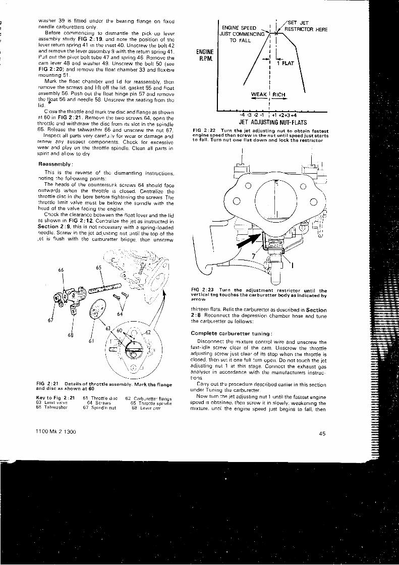
washer 39 is f i t ted under the bear ing f lange on f ixedneedle carburet ters only.
Before commencing to d ismant le the pick-up leverassemb ly s t udy F IG 2 :19 , and no te t he pos i t i on o f t helever return spr ing 41 in the inset 40. Unscrew the bol t 42and remove the lever assembly g wi th the return spr ing 41 .Pul l out the pivot bol t tube 47 and spr ing 46. Remove thecam lever 48 and washer 49. Unscrew the bol t 50 (seeF IG 2 :20 ) and remove t he f l oa t chamber 33 and f l ex i b l emoun t i ng 51 .
Mark the f loat chamber and l rd for reassembly, thenremove the screws and l i f t of f the l id, gasket 55 and f loatassembly 56. Push out the f loat h inge pin 57 and remove
l .he f t roat 56 and needle 58. Unscrew the seat ing f rom the
i lo.Close the throt t le and mark the disc and f lange as shown
a t 60 i n F IG 2 :21 . Remove t he two sc rews 64 . ooen t hethrot t le and wi thdraw the disc f rom i ts s lot in the spindte65. Release the tabwasher 66 and unscrew the nut 67.
Inspect a l l parts very careful ly for wear or damage andrenew any suspect components. Check for excesstvewear and play on the throt t le spindle. Clean al l parts insp i r i t and a l l ow t o d r y .
Reassemb ly :
This is the reverse of the dismant l ing instruct ions,no t i ng t he f o l l ow ing po in t s :
The heads of the countersunk screws 64 should faceoutwards when the throt t le is c losed. Central ize thethrot t le d isc in the bore before t ightening the screws. Thethrot t le l imi t valve must be below the spindle wi th thehead o f t he va l ve f ac i ng t he eng ine .
Check the c learance between the f loat lever and the l idas shown i n F IG 2 :12 . Cen t ra l i ze t he j e t as i ns t r uc ted i nSec t i on 2 : 9 , t h i s i s no t necessa ry w i t h a sp r i ng - l oaoeoneedle. Screw in the jet adjust ing nut unt i l the top of tnelet is f lush wi th the carburet ter br idge, then unscrew
\
m09/ 967
168
F I G 2 : 2 1 D e t a i l s o f t h r o t t l e a s s e m b l y . M a r k t h e f l a n g ea n d d i s c a s s h o w n a t 6 0
ENGINERPIYt
JET AOJUSTING NUT-FLATSFIG 2:22 Turn the jet adjust ing nut to obtain fastestengine speed then screw in the nut unt i l speed just star tst o f a l l . Tu rn nu t one f l a t down and l ock t he res t r i c t o r
66
62 Carbure t te r f lange65 Thro t r le sp ind le68 Lever a rm
F IG 2 :23 Tu rn t he ad jus tmen t r es t r i c t o r un t i l t hevert ical tag touches the carburet ter body as indicated bya r row
thir teen f lats. Ref i t the carburet ter as descr ibed in Sect ion2 :8 . Reconnec t t he dep ress ion chamber hose and t unethe carburet ter as fo l lows:
Comp le te ca rbu re t t e r t un i ng :
Disconnect the mixture contro l wire and unscrew thefast- id le screw clear of the cam. Unscrew the throt t leadjust ing screw just c lear of i ts stop when the throt t le isc losed, then set i t one fu l l turn open. Do not touch the jetadjust ing nut 1 at th is stage. Connect the exhaust gasanalyser in accordance wi th the manufacturers instruc-t i ons .
Carry out the procedure descr ibed ear l ier in th is sectronunder Tuning the carburet ter .
Now turn the Jet adjust ing nut 1 unt i l the fastest enginespeed is obtained, then screw i t in s lowly. weakening themixture, unt i l the engine speed just begins to fa l l , then
Key t o F i g 2 :21 61 Th ro t r t e d i sc63 Limi t valve 64 Screws66 Tabwasher 67 Spindle nur
1100 t vk 2 1300 45
SET JET
-4 A 2. -1
" +1 +2+3+4
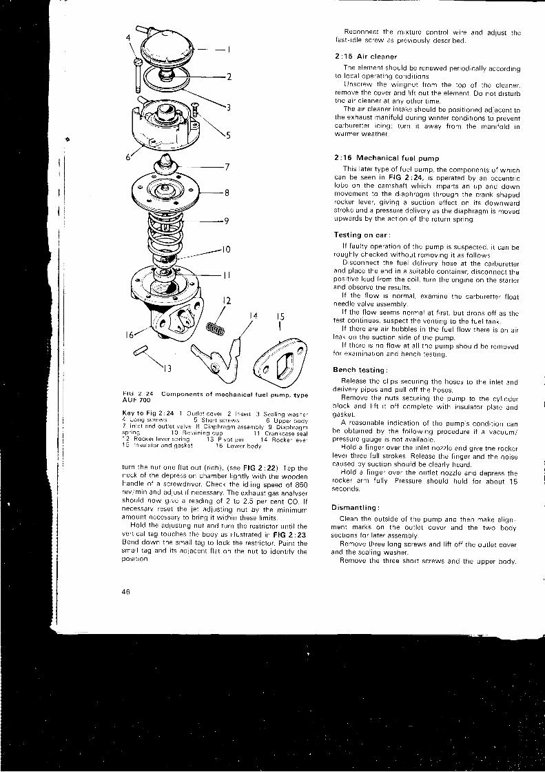
C o m p o n e n t s o f m e c h a n i c a l f u e l p u m p , t y p e
Key to F ig 2 :24 1 Ou t l e t cove r 2 I nse r t 3 Sea l i no washe r4 Long screws 5 Short screws 6 Up-per body7 I n l e t and ou t l e t va l ve 8 D iaph ragm assemb ly 9 d i aph ragn rsp r i ng 10 Re ta rn rng cup 1 1 C rankcase sea l12 Rocke r l eve r sp r rng 13 P i vo t p i n 14 Rocke r l eve r15 l nsu la to r and gaske t 16 Lower body
tu rn t he nu t one f l a t ou t ( r i ch ) , ( see F IG 2 :22 ) . f ap theneck of the depression chamber l ignt ly wi th the woodenhand le o f a sc rewd r i ve r . Check t he i d l i ng speed o f g50rev/min and adjust i f necessary. The exhaust gas analysershould now give a reading of 2 to 2.5 per cent CO. l fnecessa ry r ese t t he j e t ad jus t i ng nu t by t he m in imumamount necessary to br ing I t wi th in these l imi ts.
Ho ld t he ad lus t i ng nu t and t u rn t he res t r i c t o r un t i l r neve r t i ca l t ag t ouches t he body as i l l u s t r a ted i n F IG 2 :23 .Bend down the smal l tag to lock the restr ic tor . paint thesmal l tag and i ts adjacent f lat on the nut to ident i fy thepos r t r on .
4 0
Reconnec t t he m ix tu re con t ro l w i r e and ad jus t t hefast- id le screw as previously descr ibed.
2 : 1 5 A , i r c l e a n e r
The e l emen t shou ld be renewed pe r i od i ca l l y acco rd i ngto l oca l ope ra t i ng cond i t i ons .
Unsc rew the w ingnu t f r om the t op o f t he c l eane r ,remove the cover and l i f t out the element. Do not d isturbthe a i r c l eane r a t any o the r t ime .
The air c leaner intake should be posi t ioned adjacent tot he exhaus t man i f o l d du r i ng w in te r cond i t i ons t o p reven tcarburet ter ic ing; turn i t away f rom the mani fo ld inwarmer weather.
2 : 1 6 M e c h a n i c a l f u e l p u m p
This later type of fuel pump, the components of whichcan be seen i n F IG 2 :24 , i s ope ra ted bv an eccen t r i cl obe on t he camsha f t wh i ch impa r t s an up and downmovemen t t o t he d i aph ragm th rough t he c rank -shapeorocker lever, g iv ing a suct ion ef fect on i ts downwarostroke and a pressure del ivery as the diaphragm is movedupwards by t he ac t i on o { t he re tu rn sp r i ng .
Tes t i ng on ca r :
l f f au l t y ope ra t i on o f t he pump i s suspec ted , i t can berough l y checked w i t hou t r emov ing i t as f o l l ows :
Disconnect the fuel del ivery hose at the carburet terand p l ace t he end i n a su i t ab le con ta i ne r , d i s connec t t hepos i t i ve l ead f r om the co i l , t u rn t he eng ine on t he s ta r re rand observe the resul ts.
l f t he f l ow i s no rma l , exam ine t he ca rbu re t t e r f l oa tneedle valve assembly.
l f t he f l ow seems no rma l a t f i r s t , bu t d rops o f f as t hetest cont inues, suspect the vent ing to the fuel tank.
l f t he re a re a i r bubb les i n t he f ue l f l ow t he re i s an a i rl eak on t he suc t i on s i de o f t he pump .
l f t he re i s no f l ow a t a l l t he pump shou ld be removedfo r exam ina t i on and bench t es t i no .
Bench t es t i ng :
Re lease t he c l i ps secu r i ng t he hoses t o t he l n l e t anode l i ve r y p i pes and pu l l o f f t he hoses .
Remove t he nu t s secu r i ng t he pump to t he cy l i nde rb l ock and l i f t i t o f f comp le te w i t h i nsu la to r p l a te andg a ske t .
A reasonab le i nd i ca t i on o f t he pump ' s cond i t i on canbe ob ta i ned by t he f o l l ow ing p rocedu re i f a vacuum/p ressu re gauge i s no t ava i l ab l e .
Ho ld a f i nge r ove r t he i n l e t nozz le and g i ve t he rocke rl eve r t h ree f u l l s t r okes . Re lease t he f i nge r and t he no i secaused by suc t i on shou ld be c l ea r l y hea rd .
Ho ld a f i nge r ove r t he ou t l e t nozz le and dep ress t herocke r a rm fu l l y . P ressu re shou ld ho ld f o r abou t 15seconds .
D i s m a n t l i n g :
C lean t he ou t s i de o f t he pump and t hen make a l i gn -ment marks on the out let cover and the two bodvsect ions for later assembly.
Remove three long screws and l i f t of f the out let coverand t he sea l i ng washe r .
Remove the three short screws and the upper body.
2
/
@
t l ( j 2 1 2 4A U F 7 O O

Take out the combined in let /out let valve, not ing that th isis a press f i t and care must be taken not to damage thef ine edge.
Withdraw the insert f rom the out let cover.Holding the diaphragm and rocker lever against the
pressure of the spr ing, tap out the pivot p in and removethe lever and spr ing.
W i thd raw the d i aph ragm and sp r i ng . l t w i l l be f oundadvisable to apply a spot of o i l to the crankcase seal toavoid damage as the spindle st i r rup is pul led through.
The crankcase seal and reta in ing cup need be removeoonly i f the seal is to be renewed. This is bes. done ovsc rew ing t he cen t re o f t oo l 18G 1 119 i n t o t he cup andpu l l i ng ou t .
DExamine a l l t he componen ts , pa r t i cu l a r l y t he d i a -
phragm, for wear or damage and renew i f necessary. Thef ine edge and l ips of the in let /out let valve must a lso beclosely inspected.
Reassemb ly :
This is a reversal of the dismant l ing procedure, not ingthe fo l lowing points:
Having pressed the retarning cup into the lower booy(1 8G 1 1 1 9) , remove any sharp edges f rom the diaphragmspindle and st i r rup, o i l l ight ly and posi t ion the s lot forengagement by the rocker lever.
Ensure that the in let /out let valve groove registers rnthe housing and that the f ine edge contacts the seat tngevenry.
Line up the screw holes in the lower bodv and dia-phragm, press down the rocker lever so that the diaphragml ies f lat and loosely f i t the three short screws. Fi t theseal ing washer and out let cover then t ighten al l screwseven l y .
I t is advisable to dry test the pump as descr ibed abovebefore f i t t ing to the engine.
2 :17 Fau l t d i agnos i s
(a) Leakage or insuf f ic ient fuel del ivered
I Air vent in fuel tank restr ic ted2 Fuel p ipes blocked3 Air leaks at p ipe connecrrons4 Pump f i l ter b locked5 Pump gaskets faul ty6 Pump diaphragm defect ive7 Pump valves st ick ing or seat ing badly8 Fuel vapor iz ing in p ipel ines due to heat
(b) Excessive fuel consumpt ion
1 Carburerter(s) need adjust ing2 Fuel leakage3 St ick ing mixture contro l4 D i r t y a i r c l eane r5 Excessive engine temperature6 Brakes binding7 Tyres under- inf lated8 l d l i ng speed t oo h i gh9 Car over loaded
(c ) l d l i ng speed t oo h i gh
1 R i ch f ue l m i x tu re2 Carburet ter contro ls st ick ing3 Slow-running screws incorrect ly adjusted4 Worn carburetter butterfly valve
1 1 0 0 M k 2 1 3 0 0
(d ) No isy fue l pump
1 Loose mountings2 Air leaks on suction side and at diaphragm3 Obstruction in fuel pipe4 Clogged pump f i l ter
(e ) No fue l de l i very1 Float needle stuck2 Vent in tank blocked3 Electr ical connections to pump faulty4 Pump contact points dirty5 Pipel ine obstructed6 Pump diaphragm sti f f or damaged7 In le t va lve in pump s tuck openB Bad air leak on suction side of pump
Fau l t d iagnos is
The fol lowing i tems apply when an exhaust emissioncontrol system is f i t ted (see also chapter 1, section1 :25).
(f) Backfire in exhaust system1 Leaks in hoses or connections to gulp valve or vacuum
sensing pipe2 Faulty gulp valve3 Leak in intake system4 High inlet manifold depression on overrun. Faurrv
carburetter l imit valve
(g) Hesitat ion to accelerate after sudden thrott leclosure
' I Check 1 , 2 and 3 in ( f )
(h ) Eng ine surges1 Check 1 and 2 in ( f )
( j ) Er ra t i c id l ing or s ta l l ing1 Check 1 and 2 in (f)2 Carburetter l imit valve not seating
(k) Burned or baked hose between air pump andcheck valve
1 Faultv check valve2 Faulty air pump
( l ) No isy a i r pump
1 Incorrect belt tension2 Pulleys damaged, loose or misal igned3 Air pump damaged or seizing
(m) Excessive exhaust system temperature1 Incorrect ignit ion t iming2 Air injector missing3 Air pump rel ief valve inoperative4 Mixture control (choke) not ful ly returned
(n) Mixture requires enrichment to obtain correctexhaust emission readings
1 Air leak in crankcase2 Crankcase breather hose or carburetter connections
leaking
(o) Fue l l€akage
1 Broken fuel pipe2 Fi l ler cap not seal ing3 Leak on f i l ler tube or tank unit
47
CHAPTER 3
T H E I G N I T I O N S Y S T E M
3 : 1 Desc r i p t i on3 : 2 R o u t i n e m a i n t e n a n c e3 : 3 l gn i t i on f au l t s3 : 4 Remov ing and d i sman t l i ng d i s t r i bu to r
3 : 1 D e s c r i p t i o n
A l l t he ca rs cove red by t h r s manua l a re f i t t ed w i t h aLu cas d is t r lbuto r , lype 25D4 or 45D4, wh ich incorporatesan au toma t i c t im ing con t ro l ope ra ted by a cen t r i f uga lmechan i sm and a l so a vacuum ope ra ted un t t wh i chregu la tes t he i gn i t i on t im ing acco rd i ng t o eng ine l oad . Ahand operated micrometer adjuster is inc luded to enablesl ight a l terat ions to be made convenient ly to sui t var iousg rades o f f ue l o r changes i n eng ine cond i t i on .
The weights of the centr i fugal system tend to f ly out-wa rds as t he eng ine speed i nc reases and t h rough a l i n kagemove the contact breaker re lat ive to the dist r ibutor dr iv ingshaft and so advance the actual point of f i r ing as requireda t h i n h o r c n o o d c
A smal l bore pipe f rom the in let mani fo ld to the vacuumunr t pe rm i t s t he dep ress ion i n t he man r fo l d t o advance o rretard the set t ing according to engine load. At smal lt h ro t t l e open ings , w i t h a l ow l oad on t he eng ine , dep res -s i on i s h i gh and t he un i t advances t he i gn i t i on . Thereduced vacuum ob ta j n i ng when c l rmb ing h i l l s on w ide rthrot t le openings causes the uni t to retard the f i r ing point .
These two contro ls may be seen in the exploded v iew oft h e d i s t r i b u t o r i n F I G 3 : 1 .
1 1 0 0 M k 2 1 3 0 0
3 : 5 T i m i n g t h e i g n i t i o n3 : 6 S p a r k i n g p l u g s3 : 7 D i s t r i b u t o r d r i v i n g s p i n d l e3 : 8 F a u l t d i a g n o s i s
3 : 2 R o u t i n e m a i n t e n a n c e
Maintenance consists of keeping the dist r ibutor c leana t a l l t imes and occas iona l d rops o f o i l as f o l l ows :
Remove the dist r ibutor cap 2 (see FIG 3 :1) and l i f t of ft he ro to r 4 f r om the cam sp ind le 11 . App l y a f ew d rops o fo i l r n t o t he recess 5 ( see F IG 3 :2 ) . l t i s no t necessa ry t oremove the screw as c learance is provided.
Apply a few drops down the aperture 4 on to thecentr i f ugal advance mechanrsm, but beware of let t ing theoi l reach the contact breaker p late or the points.
A drop of o i l may be appl ied to the contact breakerpivot and a smear of grease on the cam as shown in FIG3 : 3 .
Ad jus t ing the contac t b reaker po in ts (see F IG 3 :2 ) :
First turn the engine unti l one of the cams has openedthe points to the ful lest extent and measure the gap. Thiss h o u l d b e b e t w e e n . 0 1 4 a n d . 0 1 6 i n c h . l f i t i s o u t s i d ethese l imits, slacken off the contact plate securing screw 2,place a screwdriver in the slot 3 and twist gently unti l thegap is correct when measured with a feeler gauge. Tightenthe screw and check .
49
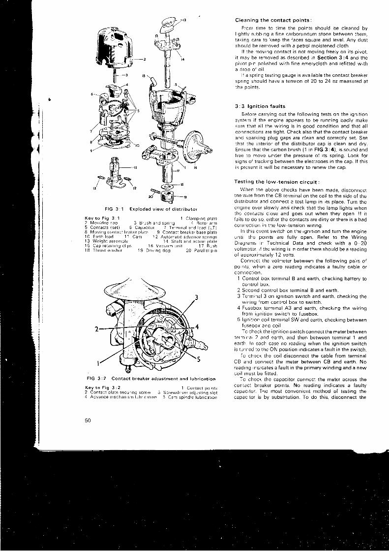
m-,,,,/*@\.
F I G 3 : 1 E x o l o d e d v i e w o f d i s t r i b u t o r
K e y t o F i g 3 : 1 1 C l a m p i n g p l a t e2 M o u l d e d c a p 3 B r u s h a n d s p r i n g 4 R o t o r a r m5 C o n t a c t s ( s e t ) 6 C a p a c i t o r 7 T e r m r n a l a n d l e a d ( L T )8 Mov ing contac t b raker p ld te 9 Contac t b reaker base p la te1 O E a r t h l e a d 1 1 C a m 1 2 A u t o m a t r c a d v a n c e s p r r n g s1 3 W e i g h t a s s e m b l y 1 4 S h a f t a n d a c t r o n p l a t e1 5 C a p r e t a i n i n g c l i p s 1 6 V a c u u m u n i t 1 7 B u s h1 8 T h r u s t w a s h e r 1 9 D r i v i n g d o g 2 0 P a r a l l e l p i n
Clean ing t he con tac t po in t s :
From t ime to t ime the points should be c leaned byl i gh t l y r ubb ing a f i ne ca rbo rundum s tone be tween t hem,taking care to keep the faces square and level . Any dustshould be removed wi th a petro l moistened c loth.
l { the moving contact is not moving f reely on i ts p ivot ,i t may be removed as desc r i bed i n Sec t i on 3 :4 and t hepivot p in pol ished wi th f ine emerycloth and ref i t ted wi tha d rop o f o i l .
l f a spr ing test ing gauge is avai lable the contact breakerspr ing should have a tension of 20 to 24 oz measured att he oo rn t s .
3 : 3 l g n i t i o n f a u l t s
Before carry ing out the fo l lowing tests on the igni t ionsystem i f the engine appears to be running badly makesu re t ha t a l l t he w i r i ng i s i n good cond i t i on and t ha t a l lconnect ions are t ight . Check also that the contact breakerand sparking plug gaps are c lean and correct ly set . Seethat the interror of the dist r ibutor cap is c lean and dry.Ensu re t ha t t he c6 rbon b rush (1 i n F IG 3 : 4 ) , i s sound anofree to move under the pressure of i ts spr ing. Look fors igns of t racking between the electrodes in the cap. l f th isis present i t wi l l be necessary to renew the cap.
Tes t i ng t he l ow - tens ion c i r cu i t :
When the above checks have been made, d isconnectthe wrre f rom the CB terminal on the coi l to the s ide of thedistr ibutor and connect a test lamp in i ts p lace. Turn theeng ine ove r s l ow l y and check t ha t t he l amp l i gh t s whenthe contacts c lose and goes out when they open. l f i tfa i ls to do so, e i ther the contacts are di r ty or there is a badconnec t i on i n t he l ow - tens ion w i r i ng .
In th is event swi tch on the igni t ion and turn the engineun t i l t he po in t s a re f u l l y open . Re fe r t o t he W i r i ngDiagrams in Technical Data and check wi th a 0-20vol tmeter. l f the wir ing is in order there should be a readingo f app rox ima te l y 12 vo l t s .
Connect the volmeter between the fo l lowing pairs ofpoints, when a zero reading indicates a faul ty cable orconnec t i on ,
1 Control box terminal B and earth, checking bat tery tocontro l box.
2 Second contro l box terminal B and earth.3 Terminal 3 on igni t ion swi tch and earth, checking the
wir ing f rom contro l box to swi tch.4 Fusebox t e rm ina l A3 and ea r t h , check ing t he w i r i ng
from igni t ion swrtch to fusebox.5 Igni t ion coi l terminal SW and earth, checking between
fusebox and co i l .To check the igni t ion swi tch connect the meter between
terminal 2 and earth, and then between terminal 1 andearth In each case no reading when the igni t ion swi tchis turned to the ON posi t ion indicates a faul t in the swi tch.
To check the coi l d isconnect the cable f rom terminalCB and connect the meter between CB and earth. Noreading indicates a faul t in the pr imary winding and a newcoi l must be f i t ted.
To check the capaci tor connect the meter across thecontact breaker points. No reading indicates a faul tycapaci tor . The most convenient method of test ing thecapaci tor is by subst i tut ion. To do th is, d isconnect the
F I G 3 : 2 C o n t a c t b r e a k e r a d j u s t m e n t a n d l u b r i c a t i o n
K e y t o F i g 3 : 2 ' 1 C o n t a c t p o i n t s
2 Contac t p la te secur ing screw 3 Screwdr iver ad jus t ing s lo t4 A d v a n c e m e c h a n i s m l u b r i c a t r o n 5 C a m s p i n d l e l u b r i c a t t o n
50
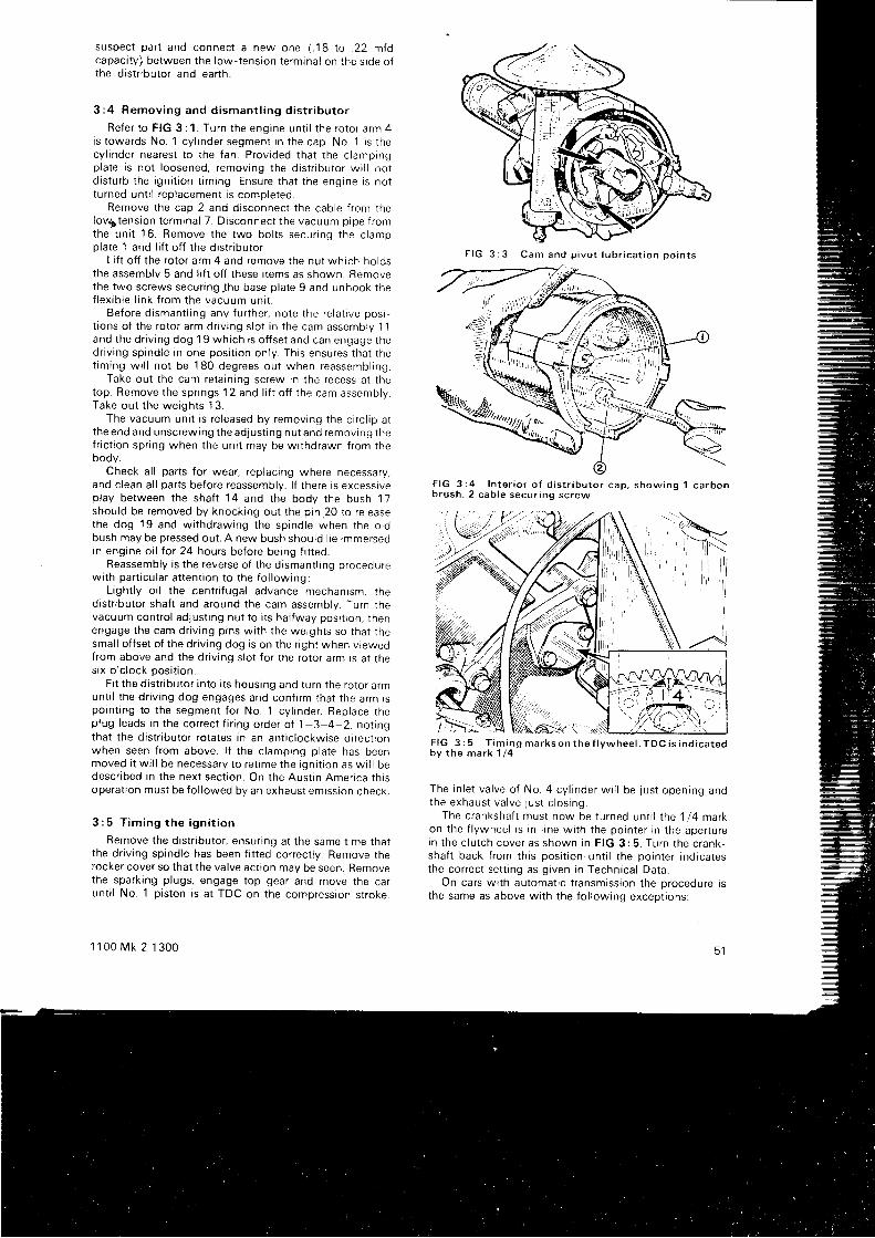
suspec t pa r t and connec t a new one ( . 18 t o .22 m fdcapaci t , i ) between the low-tension terminal on the s ioe olthe dist r ibutor and earth.
3 :4 Remov ing and d i sman t l i ng d i s t r i bu to r
Re fe r t o F IG 3 : 1 . Tu rn t he eng ine un t r l t he r o to r a rm 4rs towards No. 1 cyl rnder segment in the cap. No. 1 is thecyl inder nearest to the fan. Provided that the c lampingplate is not loosened, removing the dtst f lbutor wi l l notd i s t u rb t he i gn i t i on t im ing . Ensu re t ha t t he eng ine i s no tturned unt i l replacement is completed.
Remove the cap 2 and disconnect the cable f rom thelou5tension terminal 7. Disconnect the vacuum pipe f romthe un i t 16 . Remove t he two bo l t s secu r i ng t he c l ampplate '1
and l i f t of f the dist r ibutorLi f t of f the rotor arm 4 and remove the nut which horos
the assembly 5 and l i f t of f these i tems as shown. Removethe two screws secur ing lhe base plate 9 and unhook thef l ex i b l e l i n k f r om the vacuum un i r .
Be fo re d i sman t l i ng any f u r t he r , no te t he re l a t t ve pos lt ions of the rotor arm dr iv ing s lot in the cam assembly 11and t he d r i v i ng dog 19 wh i ch r s o f f se t and can engage t hed r i v i ng sp ind le i n one pos i t i on on l y . Th rs ensu res t ha t t het im ing w i l l no t be 180 deg rees ou t when reassemb l i ng .
Take out the cam retain ing screw in the recess at thetop. Remove the spr ings 12 and l i f t of f the cam assembly.Take ou t t he we igh t s 13 .
The vacuum uni t is re leased by removing the c i rc l ip atthe end and unscrewing the adjust ing nut and removing thefr ic t ion spr ing when the uni t may be wi thdrawn from thebody.
Check al l parts for wear, replacing where necessary,and c lean al l parts before reassembly. l f there is excessrveplay between the shaf t 14 and the body the bush 17should be removed by knocking out the pin.20 to re leasethe dog 19 and w i t hd raw ing t he sp ind le when t he o l dbush may be pressed out . A new bush should l ie rmmersedin engine oi l tor 24 hours before being f i t ted.
Reassembly is the reverse of the dtsmant l ing procedurewith part icular at tent ion to the fo l lowing:
Light ly o i l the centr i fugal advance mechanism, thedistr ibutor shaf t and around the cam assembly. Turn thevacuum contro l adjust ing nut to i ts hal fway posi t ion, tnenengage the cam dr iv ing pins wi th the weights so that thesmal l of fset of the dr iv ing dog is on the r ight when v iewedfrom above and the dr iv ing s lot for the rotor arm is at thes i x o ' c l ock pos i t i on .
Fi t the dist r ibutor into i ts housing and turn the rotor armunt i l the dr ivrng dog engages and conf i rm that the arm tspoint ing to the segment for No. 1 cyl inder. Replace theplug leads in the correct f i r ing order of 1-3-4-2, not ingthat the dist r ibutor rotates in an ant ic lockwise di rect ionwhen seen f rom above. l f the c lamping plate has beenmoved i t wi l l be necessary to ret ime the igni t ion as wi l l bedescnbed in the next sect ion. On the Aust in America th isoperat ion must be fo l lowed by an exhaust emission check.
3 : 5 T i m i n g t h e i g n i t i o n
Remove the dist r ibutor , ensur ing at the same t ime thatthe dr iv ing spindle has been f i t ted correct ly . Remove therocker cover so that the valve act ion may be seen. Removethe sparking plugs, engage top gear and move the carunt i l No. 1 p iston is at TDC on the compression stroke.
1 1 0 0 M k 2 1 3 0 0
F I G 3 C a m a n d p i v o t l u b r i c a t i o n p o i n t s
F I G 3 : 4 I n t e r i o r o f d i s t r i b u t o r c a p , s h o w i n g 1 c a r b o nb r u s h , 2 c a b l e s e c u r i n g s c r e w
F IG 3 : 5 T im ing marks on t he f l ywhee l . TDC i s i nd i ca tedbv t he mark 1 /4
The i n l e t va l ve o f No . 4 cy l i nde r w i l l be j us t open ing andthe exhaus t va l ve j us t c l os i ng .
The crankshaft must now be turned unt i l the 1/4 markon the f lywheel is in l rne wi th the pointer in the aperturei n t he c l u t ch cove r as shown i n F IG 3 :5 . Tu rn t he c rank -shaf t back f rom th is posi t ion unt i l the pointer indicatesthe correct set t ing as given in Technical Data.
On cars wi th automat ic t ransmission the procedure isthe same as above wi th the fo l lowing except ions:
5 1
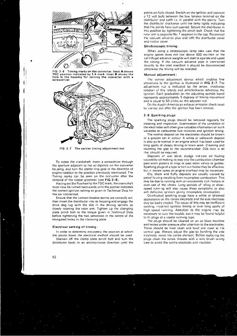
F I G 3 : 6 f i m i n g m a r k s o n t h e c o n v e r t e r . I n s e t A s h o w sT D C p o s i t i o n i n d i c a t e d b y 1 / 4 m a r k . I n s e t B s h o w s t h eh o l e i n t h e h o u s i n g f o r t u r n i n g t h e c o n v e r t e r w i t h ascrewdr iver
T h e v e r n i e r t i m i n g a d j u s t m e n t n u t
To rotate the crankshaft , insert a screwdr iver throughthe aperture adjacent to the oi l d ipst ick on the converterhousing, and turn the star ter r ing gear in the di rect ion ofengine rotat ion to the posi t ion previously ment ioned. TheTiming marks can be seen on the converter af ter theremova l o f t he rubbe r g rommet ( see F IG 3 : 6 ) .
Having set the f lywheel to the TDC mark, the crankshaftmust now be turned backwards unt i l the pointer indicatesthe correct igni t ion set t ing as given in Technical Data fort ne ca r conce rned .
Ensure that the contact breaker points are correct ly set ,then insert the dist r ibutor into i ts housing and engage thedr ive dog lug wi th the s lot in the dr iv ing spindle byslowly rotat ing the rotor arm. Tighten up the c lampingplate p inch bol t to the torque given in Technical Databefore t ightening the two setscrews in the centre of thee longa ted ho les i n t he c l amp ing p l a te .
E lec t r i ca l se t t i ng o f t im ing :
In order to determine accuratelv the Dosi t ion at whichthe points break the electr ical method should be used:
Slacken of f the c lamp plate p inch bol t and turn thedistr ibutor body in an ant ic lockwise di rect ion unt i l the
3 Z
points are fu l ly c losed. Switch on the igni t ion and connecta 12 -vo l t bu l b be tween t he l ow - tens ion t e rm ina l on t hedistr ibutor and earth i .e. in paral le l wi th the points. Turnthe dist r ibutor c lockwise unt i l the lamp l ights indicat ingthat the points have just opened. Secure the dist r ibutor inth is posi t ion by t ightening the pinch bol t . Check that therotor arm is opposi te No. 1 segment in the cap. Reconnectthe vacuum advance oipe and ref i t the dist r ibutor coverand rocker cover.
S t roboscop i c t im ing :
When using a stroboscopic lamp take care that theengine speed does not r ise above 600 revlmin or thecentr i f ugal advance weights wi l l s tar t to operate and upsett he t im ing . l f t he vacuum advance p i pe i s connec teddirect ly to the in let mani fo ld i t should be disconnectedotherwise the t iming wi l l be retarded.
Manua l ad jus tmen t :
The vernier adjustment device which enables f inea l t e ra t i ons t o t he i gn i t i on i s i l l u s t r a ted i n F IG 3 :7 . Theadjustment nut is indicated by the arrow; c lockwrserotat ion of th is retards and ant ic lockwise advances theign i t i on . Each g radua t i on on t he ad lus t i ng sp ind le bane lrepresents approximately 5 degrees of t iming movementand i s equa l t o 55 c l i c ks on t he adJus te r nu t .
On the Aust in America an exhaust emission check mustbe carr ied out af ter the igni t ion has been ret imed.
3 : 6 S p a r k i n g p l u g s
The sparkrng plugs should be removed regular ly forc leaning and inspect ion. Examinat ion of the condi t ion ofthe electrodes wi l l of ten give valuable informat ion on suchvar iables as carburet ter f uel mixtures and igni t ion t iming.
The normal deoosi t on the electrodes should be brownor a greyish tan in colour. A whi te or yel lowish deposi tis a lso qui te normal in an engine which has been used forlong spel ls of steady dr iv ing or town work. Cleaning andreset t ing the gap to the recommended .025 inch rs a l lt ha t shou ld be requ i r ed .
Depos i t s o f we t b l ack s l udge i nd i ca te o i l f ou l i ngcaused by oi l making i ts way into the combust ion chamberpast worn pistons or r ings or past worn valves or guides.Sparking plugs of a type which run hot ter may be ef fect ive,but in severe cases an engine overhaul may be necessary.
Dry, b lack and f luf fy deposi ts are usual ly caused bypetro l foul ing resul t ing f rom incomplete combust ion. Thismay be due to running wi th ah excessively r ich mixture orover-use of the choke. Long per iods of id l ing or s low-speed running wi l l a lso cause these symptoms as alsow i l l de fec t i ve i gn i t i on g i v i ng i ncomp le te combus t i on
Overheated sparking plugs have a whi te or b l is teredappearance on the centre e lectrode and the s ide electrodemay be badly eroded. The cause of th is may be inef f ic ientcoo l i ng , i nco r rec t i gn i t i on t im ing o r ove r l ong spe l l s o fh i gh -speed runn ing . A t t en t i on t o t he eng ine may benecessary to cure the t rouble, but i t may be found helpf t r lt o f i t p l ugs o f a coo le r r unn ing t ype .
The p l ugs shou ld be c l eaned on an a i r b l as t mach ineand tested under pressure af ter at tent ion to the electrodes.These should be f i led c lean and level and reset to thecorrect gap. Always adjust the gap by bending the s ideelectrode, never the centre e lement. Before replacing theplugs c lean the screw threads wi th a wire brush takingcare to avoid the centre e lectrode and insulator .
, li-
F I G 3 : 7
High - t ens ion cab les :
l f a h igh-tension cable shows s igns of deter iorat ion i tshould be replaced by new rubber covered igni t ion cabre.
To make the connect ions to the terminals in the dis-t r ibutor cover, s lacken the secur ing screws on thejnstoeof the moulding (2 in FIG 3 :4) and pul l out the otd cables.Having cut the new cables to the correct length push oneend f i rmly into the hole af ter smear ing wi th s i l icone greaseand t ighten the screw.
To f i t the cable to the igni t ion coi l pass the caorethrough the knur led moulded nut , bare about I inch ofthe wire, thread i t through the brass washer and fan outthe wires over the face of the washer. Screwing the nutinto $e terminal socket wi l l hold i t f i rmly in p lace.
3 :7 D i s t r i bu to r d r i v i ng sp ind le
l f for any reason the dr iv ing spindle has been removedfrom r ts housing in the crankcase, i t must be correct lyengaged.wi th the camshaft gear as descr ibed in Chapter1 . S e c t i o n 1 : 7 .
1 1 0 0 M k 2 1 3 0 0
3 : 8 F a u l t d i a g n o s i s
(a ) Eng ine w i l l no t f i r e
1 Battery d ischarged2 Distr ibutor contact points d i r ty , p i t ted or maladlusted3 Drstr ibutor cap di r ty , cracked or
' t racking'
4 Carbon brush in d ist r ibutor cap not touchtng rotor5 Fau l t y cab le o r l oose connec t i on i n l ow - tens ion c i r cu i t6 Distr ibutor rotor arm cracked7 Faul ty coi l8 Broken contact breaker spr ing9 Contact points stuck open
(b ) Eng ine m is f i r es
1 C h e c k 2 , 3 , 5 a n d 7 i n ( a )2 Weak contact breaker spr ing3 High-tension plug and coi l leads cracked or per ished4 Spa rk i ng p l ug (s ) l oose5 Spa rk i ng p l ug i nsu la t i on c racked6 Spa rk i ng p l ug gap rnco r rec t l y se t7 l gn i t i on t im ing t oo f a r advanced
53
CHAPTER 4
THE COOLING SYSTEM
4 : 14 : 24 : 34 : 44 . . 5
Desc r i p t i onP ro tec t i ve ma in tenanceRemov ing rad ia to rRemov ing expans ion chamberThe f an be l t
4 : 1 D e s c r i o t i o n
A p ressu r i zed coo l i ng sys tem i s used on a l l t he ca rscove red by t h i s manua l , w i t h an expans ion chamber i n t owh i ch any excess o f coo lan t , wh i ch may resu l t f r omhea t i ng , i s d i r ec ted Pe r i od i c t opp ing up shou ld beunnecessa ry ove r l ong pe r i ods , pa r t i cu l a r l y i f t he sys temis f i l l ed w i t h an an t i f r eeze so lu t i on o f t he e thy l ene -g l yco ltvoe.
The coo l i ng wa te r i s c i r cu l a ted a round t he eng ine by animpe l l e r pump moun ted on t he f r on t o f t he eng tne andd r i ven by a be l t f r om the c ranksha f t pu l l ey , wh i ch a l sodrrves the electr ical generator or a l ternator .
The pump rece i ves i t s wa te r f r om the bo t t om tank o ft he rad ia to r and passes i t r ound t he cy l i nde r b l ock andin to t he cy l i nde r head and on t o t he t he rmos ta t va l vewh i ch p reven t s t he wa te r f r om f l ow ing i n t o t he rad ia to run t i l i t r s opened by t he wa te r r each ing a p rede te rm inedtempera tu re . Un t i l t he coo lan t r eaches t h i s va l ue ( seeTechn i ca l Da ta ) t he va l ve rema ins c l osed and d i r ec t s t hef low to the bot tom of the block bypassing the radiatorun t i l t he i nc reased hea t o f t he eng ine opens t he t he rmos ta tand comp le tes t he c i r cu i t .
A sp r i ng - l oaded va l ve i n t he expans ton t ank f i l l e r cappressur izes the system and so ra ises the temperature atwh i ch t he wa te r bo i l s . The expans ion t ank i s connec tedto t he rad ia to r t op t ank by a hose (25 i n F IG 4 : 1 ) t h rough
1 1 0 0 M k 2 1 3 0 0
4 : 6 T h e w a t e r p u m p4 : 7 The t he rmos ta t4 : 8 F r o s t p r e c a u t i o n s4 : 9 F a u l t d i a g n o s i s
wh i ch t he ove r f l ow ing wa te r passes as i t expands i n t herad ia to r . As t he t empe ra tu re o f t he coo lan t d rops a pa r t i a lvacuum i s c rea ted i n t he sys tem and t he sp i l l age i s d rawnback into the main system
A f l ow o f a i r i s d i r ec ted t h rough t he rad ia to r co re bymeans o f a f an bo l t ed t o t he wa te r pump pu l l ey t o ass i s ti n t he coo l i ng ac t i on .
4 : 2 P ro tec t i ve ma in tenance
The only lubr icat ion necessary is at intervals of '1
2,000m i l es when a sma l l amoun t o f g rease shou ld be i n t r oducedin to t he p l ugged cav i t y a t A i n F IG 4 :6 . Do no t usep ressu re l ub r i ca t i on as t h i s wou ld impa i r t he e f f i c i encyo f t he sea l .
On ea r l y ca r s t he re a re two d ra i n i ng po in t s , one unde rthe rad ia to r ( see F IG 4 :2 ) and one a t t he rea r o f t hecy l i nde r b l ock ( see F IG 4 : 3 ) . La te r ca r s have no rad ia to rdrain p lug and i t is necessary to remove the bot tom hose.Bo th d ra i n i ng po in t s and t he hea te r l ap , when f i t t ed ,should be opened to drain the system at the prescr ibedintervals, not forget t ing to col lect the coolant in a c leancon ta i ne r i f i t con ta i ns an t i f r eeze wh i ch shou ld no rma l l ymaintarn i ts ef fect iveness for two years.
When the water has ceased to f low the svstem should
55
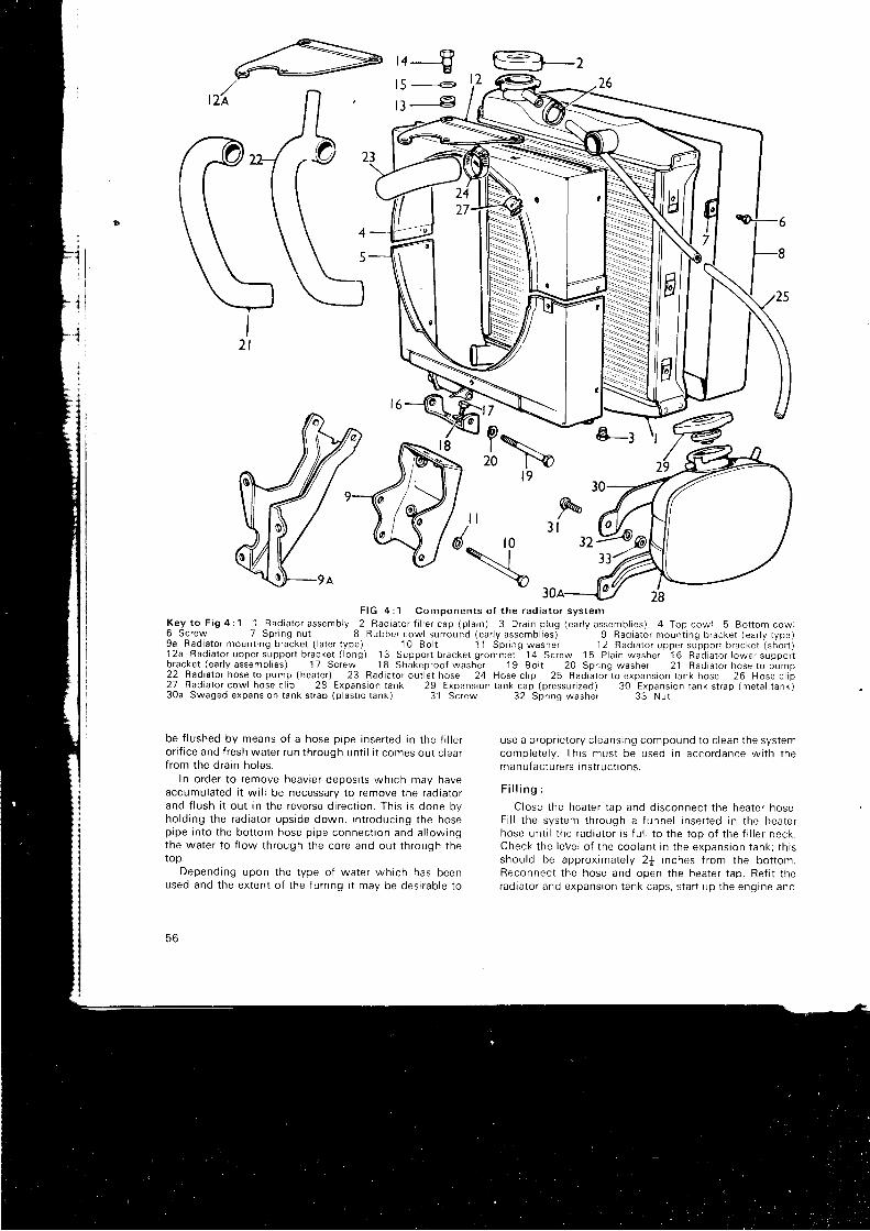
=
r4-€l5 - - .e
t3---€
B-z
1
77
F I G 4 : 1 C o m p o n e n t s o f t h e r a d i a t o r s y s t e mK e y t o F i 9 4 : ' l 1 R a d i a t o r a s s e m b l y 2 R a d i a t o r f i l l e r c a p ( p l a r n ) 3 D r a i n p l u g ( e a r l y a s s e m b l i e s ) 4 T o p c o w l 5 B o t t o m c o w l6 S c r e w 7 S p r i n g n u t 8 R u b b e r c o w l s u r r o u n d ( e a r l y a s s e m b l i e s ) 9 R a d i a t o r m o u n t i n g b r a c k e t ( e a r l y t y p e )9 a R a d i a t o r m o u n t i n g b r a c k e t ( l a t e r t y p e ) 1 0 B o l t 1 1 S p r i n g w a s h e r 1 2 R a d r a t o r u p p e r s u p p o r t b r a c k e t ( s h o r 1 )1 2 a R a d i a t o r u p p e r s u p p o r t b r a c k e t ( l o n g ) 1 3 S u p p o r t b r a c k e t g r o m m e t 1 4 S c r e w ' 1 5 P l a i n w a s h e r 1 6 R a d i a t o r l o w e r s u p p o r ib rac te t (ear ly assembl ies) 1 7 Screw 1 8 Shakeproof washer 1 9 Bo l t 20 Spr ing washer 21 Rad ia to r hose ro pump22 Radaato t hose lo pump (heater ) 23 Rad ia to r ou t le t hose 24 Hose c l ip 25 Rad ia to r to expans ion rank hose 26 Hose c l ip2 7 R a d i a t o r c o w l h o s e c l i p 2 8 E x p a n s i o n t a n k 2 9 E x p a n s i o n t a n k c a p ( p r e s s u r i z e d ) 3 0 E x p a n s i o n t a n k s t r a p ( m e t a l t a n k )
t 7
aI
20
3 0 a S w a g e d e x p a n s i o n t a n k s t r a p ( p l a s t i c t a n k ) 3 1 S c r e w 3 2 S p r i n g w a s h e r
be f lushed by means of a hose pipe inserted in the f i r rero r i f i ce and f r esh wa te r r un t h rough un t i l i t comes ou t c l ea rf rom the drain holes.
In order to remove heavrer deposi ts which may haveaccumulated i t wi l l be necessary to remove the radiatorand f l ush i t ou t i n t he reve rse d i r ec t i on . Th i s i s done byho ld i ng t he rad ia to r ups ide down , i n t r oduc ing t he hosep ipe i n t o t he bo t t om hose p i pe connec t i on and a l l ow ingthe wa te r t o f l ow t h rough t he co re and ou t t h rough t hetop.
Depending upon the type of water which has beenused and the extent of the furr ing i t may be desirable to
56
3 3 N u t
use a p rop r i e to r y c l eans ing compound t o c l ean t he sys temcomp le te l v . Th i s mus t be used i n acco rdance w i t h t hemanu fac tu re r s i ns t r uc t i ons .
F i l l i n g :
C lose t he hea te r t ap and d i sconnec t t he hea te r hose .F i l l t he sys tem th rough a f unne l i nse r t ed i n t he hea te rhose un t i l t he r ad ia to r i s f u l l t o t he t op o f t he f r l l e r neck .Check t he l eve l o f t he coo lan t i n t he expans ion t ank ; t h r sshou ld be app rox ima te l y 2 j i n ches f r om the bo t t om.Reconnec t t he hose and open t he hea te r t ap . Re f i t t herad ra to r and expans ion t ank caps , s t a r t up t he eng ine and
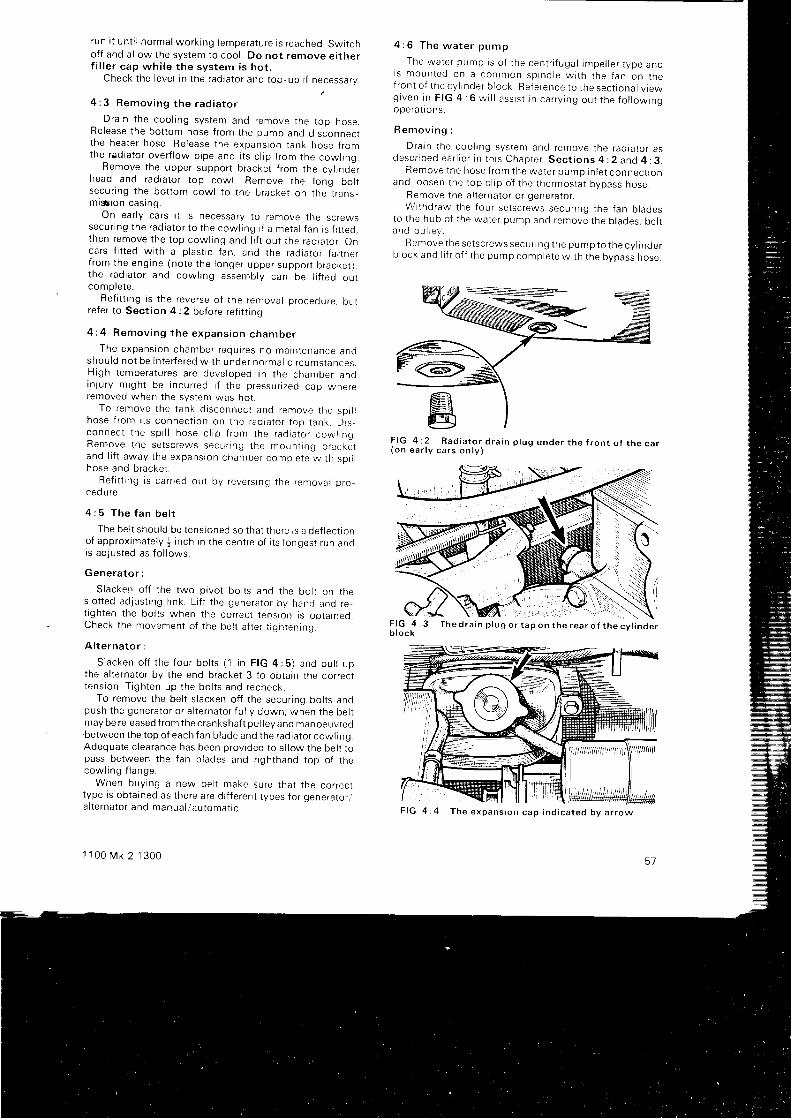
I un i t un t i l no rma l wo rk i ng t empe ra tu re i s r eached . Sw l t cho f f and a l l ow t he sys tem to coo l . Do no t r emove e i t he rf i l l e r cap wh i l e t he sys tem i s ho t .
Check t he l eve l i n t he rad ia to r and t op -up i f necessa ry .
4 : 3 R e m o v i n g t h e r a d i a t o r
D ra in t he coo l i ng sys tem and remove t he t op hose .Re lease t he bo t t om hose f r om the pump and d i sconnec tt he hea te r hose . Re lease t he expans ion t ank hose f r omthe rad ia to r ove r f l ow p i pe and r t s c l i p f r om the cow l i ng .
Remove t he uppe r suppo r t b racke t f r om the cy l i nde rhead and rad ia to r t op cow l . Remove t he l onq bo l tsecu r i ng t he bo t t om cow l t o t he b racke l on t he t r ans_m is i on cas ing .
On ea r l y ca r s i t i s necessa ry t o r emove t he sc rewssecu r i ng t he rad ia to r t o t he cow l i ng i f a me ta l { an i s f i t t ed ,t nen remove t he t op cow l i ng and l i f t ou t t he rad ta to r . Onca rs f i t t ed w i t h a p l as t i c f an , and t he rad ia to r f a r t he rf r om the eng ine (no te t he l onge r uppe r suppo r t b racke r l .t he rad ia to r and cow l i ng assemb ly can be l i f t ed ou tcompre te .
Re f i t t i ng i s t he reve rse o f t he remova l p rocedu re . bu tre fe r t o Sec t i on 4 : 2 be fo re r e f i t t i ng .
4 : 4 R e m o v i n g t h e e x p a n s i o n c h a m b e r
The expans ion chamber r equ i r es no marn tenance andshou ld no t be i n t e r f e red w i t h unde r no rma l c i r cums tances .H igh t empe ra tu res a re deve loped i n t he chamber andinyu ry m igh t be i ncu r red i f t he p ressu r i zed cap whe reremoved when the system was hot .
To remove t he t ank d i sconnec t anc l r emove t he so r r rhose f r om i t s connec t i on on t he rad ia to r t op t ank . D rs -connec t t he sp i l l hose c l i p f r om the rad ia to r cow l rng .Remove t he se t sc rews secu r i ng t he moun t i ng b racke tand l i f t away t he expans ion chamber comp le te w i t h sp r r rhose and b racke t .
Re f i t t i ng i s ca r r i ed ou t by r eve rs i ng t he f emova l p roced u re.
4 : 5 T h e f a n b e l t
The be l t shou ld be t ens ioned so t ha t t he re i s a de f l ec t i onof approximately j inch in the centre of i ts longest run andis adjusted as fo l lows:
Gene ra to r :
Slacken of f the two pivot bol ts and the bol t on rneslot ted adjust ing l ink. L i f t the generator by hanr l and re.t ighten the bol ts when the correct tension is obtained.Check t he movemen t o f t he be l t a f t e r t i . r h t en ino
A l t e rna to r :
S lacken o f f t he f ou r bo l t s ( 1 i n F IG 4 :5 ) and pu l l upthe al ternator by the end bracket 3 to obtain the correctt ens ion . T i gh ten up t he bo l t s and recheck .
To remove the bel t s lacken of f the secur ing bol ts andpush i he gene ra to r o r a l t e rna to r f u l l y down , when t he be l tmay be re leased f rom the crankshaft pul lev and manoeuvred.between the top of each fan blade and the radiator cowl ing.Adequate c learance has been provided to a l low the belr ropass between the fan blades and r ighthand top of thecow l i ng f l ange .
When buy ing a new be l t make su re t ha t t he co r rec ltype is obtained as there are di f ferent types for generator /a l t e rna to r and manua l au toma t r c .
1 1 0 0 M k 2 1 3 0 0
4 : 6 T h e w a t e r p u m p
The wa te r pump i s o f t he cen t r i f uga l impe l l e r t ype andi s moun ted on a common sp ind le w i t h t he f an on t hef ron t o f t hecy l r nde r b l ock Re fe rence t o t hesec t i ona l v i ewg i v e n r n F I G 4 : 6 w i l l a s s i s t i n c a r r y i n g o u t t h e f o l l o w i n gope ra t i ons .
R e m o v i n g :
D ra in t he coo l i ng sys tem and remove t he rad ia to r asd e s c r i b e d e a r l i e r i n t h i s C h a p t e r . S e c t i o n s 4 : 2 a n d 4 : 3 .
Remove t he hose f r om the wa te r pump i n l e t connec t i onand l oosen t he t op c l i p oJ t he t he rmos ta t bypass hose .
Remove t he a l t e rna to r o r gene ra to r .W j t hd raw the f ou r se t sc rews secunng t he f an b l ades
to t he hub o f t he wa te r pump and remove t he b l ades , be l ta n d p u l l e y .
Remove t he se t sc rews secu r i ng t he pump to t he cy l i nde rb l ock and l i f t o f f t he pump comp le te w i t h t he bypass hose .
F I G 4 : 2 R a d i a t o r d r a i n p l u g u n d e r t h e f r o n t o f t h e c a r( o n e a r l y c a r s o n l v )
F I G 4 : 3b lock
57
F I G 4 : 4 T h e e x p a n s i o n c a p i n d i c a t e d b y a r r o w
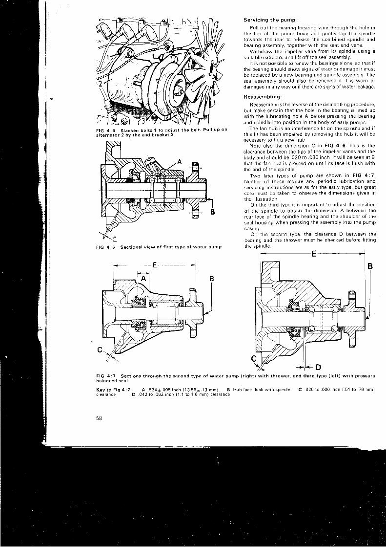
F I G 4 : 5 S l a c k e n b o l t s 1 t o a d j u s t t h e b e l t . P u l l u p o n
a l t e r n a t o r 2 b v t h e e n d b r a c k e t 3
CF I G 4 : 6 S e c t i o n a l v i e w o f f i r s t t y p e o f w a t e r p u m p
S e r v i c i n g t h e p u m p :
Pu l l ou t t he bea r i ng l oca t i ng w i re t h rough t he ho le i nt he t op o f t he pump body and gen t l y t ap t he sp ind letowa rds t he rea r t o r e l ease t he comb ined sp ind le andbea r i ng assemb ly , t oge the r w i t h t he sea t and vane .
W i thd raw the impe l l e r vane f r om i t s sp i nd le us i ng asu i t ab le ex t r ac to r and l i f t o f f t he sea l assemb ly .
I t i s no t poss ib l e t o r enew the bea r i ngs a l one . so t ha t i ft he bea r i ng shou ld show s i gns o f wea r o r damage i t mus tbe rep laced by a new bea r i ng and sp ind le assemb ly . Thesea l assemb ly shou ld a l so be renewed i f i t i s wo rn o rdamaged i n any way o r i f t he re a re s i gns o f wa te r l eakage .
Reassemb l i ng :
Reassembly is the reverse of the drsmant l tng procedure,bu t make ce r t a i n t ha t t he ho le i n t he bea r i ng i s l i ned upw i t h t he l ub r i ca t i ng ho le A be fo re p ress ing t he bea r i ngand spindle into posi t ion in the body of ear ly pumps.
The f an hub i s an i n t e r f e rence f i t on t he sp ind le and i ft h i s f i t has been impa i red by r emov ing t he hub i t w i l l benecessa ry t o f i t a new hub .
No te a l so t he d imens ion C i n F IG 4 :6 . Th i s i s t hec lea rance be tween t he t i ps o f t he impe l l e r vanes and t hebody and shou ld be . 020 t o . 030 i nch . l t w i l l be seen a t Btha t t he f an hub i s p ressed on un t i l i t s f ace i s f l u sh w i t hthe end o f t he sp ind le .
Two l a te r t ypes o f pump a re shown i n F IG 4 :7 .Ne i t he r o f t hese requ i r e any pe r i od i c l ub r i ca t i on andservic ing instruct ions are as for the ear ly type, but greatca re mus t be t aken t o obse rve t he d imens ions g i ven i nt he i l l u s t r a t i on .
On t he t h i r d t ype i t i s impo r tan t t o ad jus t t he pos i t i on
o f t he sp ind le t o ob ta i n t he d imens ion A be tween t herea r f ace o f t he sp ind le bea r i ng and t he shou lde r o f t hesea l hous ing when p ress ing t he assemb ly i n t o t he pump
cas ing .On the second type, the c learance D between the
bear ing and the thrower must be checked before f i t t ingthe sp ind le .
E
F I G 4 : 7 S e c t i o n s t h r o u g h t h e s e c o n d t y p e o f w a t e r p u m p ( r i g h t ) w i t h t h r o w e r , a n d t h i r d t y p e ( l e f t ) w r t h p r e s s u r eb a l a n c e d s e a l
Key t o F i g 4 :7 A . 534+ .005 i nch (13 .56+ .13 mm) B Hub f ace f l ush w i t h sp i nd lec l ea rance D . 042 10 . 062 i nch (1 .1 t o 1 .6 mm) c l ea rance
58
C . 0 2 0 t o . 0 3 0 i n c h ( . 5 1 t o . 7 6 m m )
4 :7 The t he rmos ta t
To remove the thermostat drain the cool ing system,disconnect the top hose and remove the cowl ing uppersupport bracket . Remove the secur ing nuts and sBrrngwashers and l i f t of f the thermostat cover f rom i ts studs.Remove the paper jo int washer and l i f t out the thermostat .See i t ems 48 t o 52 i n F IG 1 : 4 .
The thermostat can be tested by immersing i t in asui table vessel of water together wi th a re l iable thermo-meter. Now raise the temperature of the water anoobserve the reading at which the thermostat star ts roopen. Observe also that i t c loses when the water tem-perature is a l lowed to fa l l . l f the valve does not oDen at theappropl iate temperature given in Technical Data or i f i ts t icks open i t must be renewed. On no account at temotto reoair i t .
When f i t t ing a new thermostat , note that the threadedstem is uppermost. Ensure that the paper washer is notdamaged.
4 :8 F ros t p recau t i ons
To avoid the possib i l i ry of the cool ing system freezingunder winter condi t ions i t is recommended that an ant i -f reeze mixture of the ethylene type be added. l t shoulo oenoted that th is is essent ia l when a heater is f i t ted asdrain ing the cool ing system does not empty the heater .
Fi rstdrain and f lush the system, then pour in the requireoquant i ty of ant i f reeze as shown in the table below and f i l lup wi th water. To prevent the * p int of water in theexpansion chamber f rom freezing add + pint of pure antr-f reeze. Ensure that the f i l ler caps are correct ly replacedand securely t ightened.
Use only an ant i f reeze conforming to speci f icatron8S .31 51 o r BS .3152 . Th i s m i x tu re can rema in i n t hesystem for two years provided that the speci f ic gravi ty ischecked per iodical ly and f resh ant i f reeze added asrequired. Af ter the second winter , drain the svstem. f lushand ref i l l .
1 1 0 0 M k 2 1 3 0 0
Do not use radiator ant i f reezewasher.Antifreeze Starts freezing at1 * p i n t s - 9oC o r 16oF2 p i n t s - 13oC o r 9oF2 j p i n t s - 16oC o r 3oF
4 :9 Fau l t d i agnos i s
(a) lnternal water leakage
1 Cracked cyl inder wal l2 Loose cyl inder head nuts3 Cracked cyl inder head4 Faul ty head gasket5 Cracked tappet chest wal l
( b ) Poo r c i r cu l a t i on
1 Radiator core blocked2 Engine water passages restr ic ted3 Low water level4 Loose fan bel t5 Defect ive thermostat6 Per ished or col lapsed radiator hoses
(c ) Co r ros i on
1 lmpur i t ies in the water2 I n f r equen t d ra i n i ng and f l ush ing
(d ) Ove rhea t i ng
1 Check a l l i n ( b )2 Sludge in crackcase3 Fau l t y i gn i t i on t im ing4 Low oi l level in sump5 T igh t eng ine6 Choked exhaust system7 B ind ing b rakes8 S l i pp i ng c l u t ch9 Incorrect valve t iming
10 Retarded igni t ion11 M ix tu re t oo weak
in the windscreen
Absolute safe limit- 1goC o r - 3oF-26oC o r - 15oF-33oC or -28"F
59
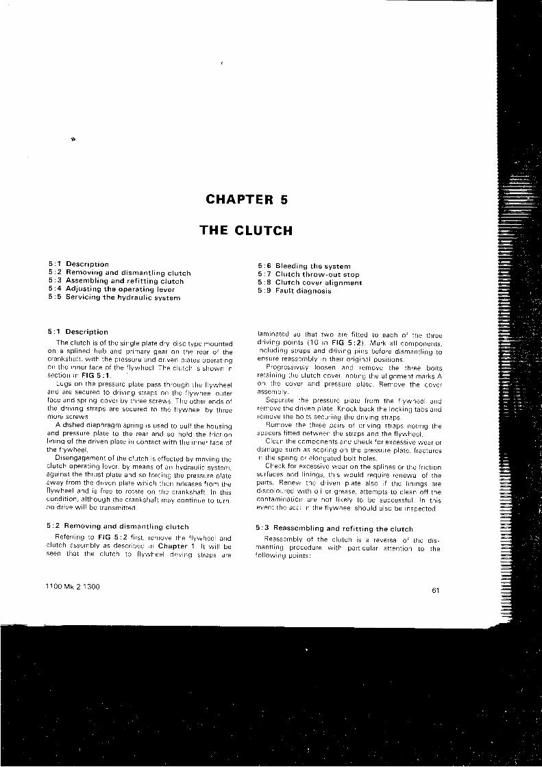
CHAPTER 5
TH E CLUTCI{
5 : 1 D e s c r i p t i o n5 : 2 R e m o v i n g a n d d i s m a n t l i n g c l u t c h5 : 3 A s s e m b l i n g a n d r e f i t t i n g c l u t c h5 : 4 Ad jus t i ng t he ope ra t i ng l eve r5 : 5 Se rv i c i ng t he hyd rau l i c sys tem
5 :1 Desc r i p t i on
The c l u t ch i s o f t he s i ng le p l a te d r y -d i sc t ype moun tedon a sp l i ned hub and p r ima ry gea r on t he rea r o f t hec ranksha f t , w i t h t he p ressu re and dnven p l a tes ope ra t t ngon t he i nne r f ace o f t he f l ywhee l . The c l u t ch i s shown i nsec t i on i n F IG 5 : 1 .
Lugs on t he p ressu re p l a te pass t h rough t he f l ywhee land a re secu red t o d r i v i ng s t r aps on t he f l ywhee l ou te rf ace and sp r i ng -cove r by t h ree sc rews . The o the r ends o tthe dr iv ing straps are secured to the |ywheel by threemore screws.
A d t shed d i aph ragm sp r i ng r s used t o pu l l t he hous ingand p ressu re p l a te t o t he rea r and so ho ld t he f r i c t i onl i n i no o f t he d r i ven p l a te i n con tac t w i t h t he i nne r f ace o ft he f l ywhee l .
D i sengagemen t o f t he c l u t ch i s e f f ec ted bv mov ino t nec lu t ch ope ra t i ng l eve r , by means o f an hyd rau l i c sys tem,aga ins t t he t h rus l p l a te and so f o r c rng t he p ressu re p l a teaway f r om the d r r ven p l a te wh i ch t hen re l eases f r om thef l ywhee l and i s f r ee t o r o ta te on t he c ranksha f t . I n t h r scond i t i on . a l t hough t he c ranksha f t may con t i nue t o t u rn ,no d r i ve w i l l be t r ansm i t t ed .
5 : 2 R e m o v i n g a n d d i s m a n t l i n g c l u t c h
Re fe r r i ng t o F IG 5 : 2 f i r s t , r emove t he f l ywhee l andc lu t ch assemb ly as desc r i bed i n Chap te r 1 . l t w i l l beseen t ha t t he c l u t ch t o f l ywhee l d r i v i ng s t r aps a re
1 1 0 0 M k 2 1 3 0 0
5 : 6 B leed ing t he sys tem5 : 7 C l u t c h t h r o w - o u t s t o p5 : 8 C l u t c h c o v e r a l i g n m e n t5 : 9 F a u l t d i a g n o s i s
l am ina ted so t ha t two a re f i t t ed t o each o t t he t h reed r i v i n g p o i n t s ( 1 0 i n F I G 5 : 2 ) . M a r k a l l c o m p o n e n r s ,i nc l ud ing s t r aps and d r i v i ng p i ns be fo re d i sman t l i ng t oensu re reassemb ly i n t he i r o r i g i na l pos i t i ons .
Progressively loosen and remove the three bol tsre ta i n i ng t he c l u t ch cove r , no t i ng t he a l i gnmen t ma rks Aon t he cove r and p ressu re p l a te . Remove t he cove rassem D ty .
Sepa ra te t he p ressu re p l a te f r om the f l ywhee l andremove t he d r i ven p l a te . Knock back t he l ock i ng t abs andremove t he bo l t s secu r i ng t he d r i v i ng s t r aps .
Remove t he t h ree pa i r s o f d r i v i ng s t r aps no t i ng t hespace rs f i t t ed be tween t he s t r aps and t he f l vwhee l .
C lean t he componen ts and check f o r excess rve wea r o rdamage such as sco r i ng on t he p ressu re p l a te , { r ac tu resIn t he sp r i ng o r e l onga ted bo l t ho l es .
Check f o r excess i ve wea r on t he sp l i nes o r t he f r i c t i onsu r f aces and l i n i ngs , t h i s wou ld r equ i r e r enewa l o f t hepa r t s . Renew the d r i ven p l a te a l so i f t he l i n i ngs a red i sco lou red w i t h o i l o r g rease , a t t emp ts t o c l ean o f f t hecon tamrna t t on a re no t l i ke l y t o be success fu l . I n t h i seven t t he sea l i n t he f l ywhee l shou ld a l so be i nspec ted .
5 : 3 R e a s s e m b l i n g a n d r e f i t t i n g t h e c l u t c h
Reassemb ly o f t he c l u t ch i s a r eve rsa l o f t he d i s -man t l i ng p rocedu re w i t h pa r t i cu l a r a t t en t i on t o t hefo l l ow ing po in t s :
6 1
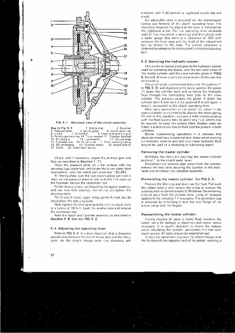
F IG 5 :1 Sec t i ona l v i ew o f t he c l u t ch assemb ly
Key t o F i g 5 :1 1 S ta r t e r r i ng 2 F l ywhee l3 Pressure plate_ ^ 1 Prl:9l.|-plaie^ _ 5 Driven plate hub6 C i r c l i p 7 C ranksha f t 8 C ranksha { l p r ima ry gea r9 P r ima ry gea r bea r i ng 1 0 Th rus t washe r 1 1 F l ywhee l hub bo l t12 D r i v i ng p i n 13 Lockwashe r 14 D r i v i ng s t r ap15 F l ywhee l hub 16 Th rus t p l a te ' 1 7 P la te r e ta i n i ng sp r i ng18 Th rus t bea r i ng 19 F l ywhee l sc rew 20 Keyed washe r21 Cove r 22 D raph ragm sp r i ng
Check , and i f necessa ry , ad jus t t he p r ima ry gea r endf l o a t a s d e s c r r b e d i n S e c t i o n 1 : 1 1 .
P lace t he p ressu re p l a te on a f l a t su r f ace w i t h t hesecu r i ng l ugs uppe rmos t and l oca te t he d r i ven p l a te , bossdownwards , on to t he c l u t ch cen t ra l r ze r t oo l 18G.684 .
F i t t he f l ywhee l ove r t he two c l u t ch p l a tes w i t h t he Amark on t he p ressu re p l a te i n l i ne w i t h t he 1 ,4 ma rk onthe f l ywhee l . Secu re t he cen t ra l i ze r t oo l .
F i t t he d r i v i ng s t r aps , no t f o rge t t i ng t he space r washe rs ,and use new l ock washe rs , bu t do no t ye t t i gh ten t hesecu r i ng bo l t s .
F i t t he c l u t ch cove r , aga in l i n i ng up t he A mark , bu t dono t t i gh ten t he re ta i n i ng bo l t s .
Now t i gh ten t he d r i v i ng s t r ap bo l t s and t he cove r bo l t st o a t o rque o f 1B l b f t . Lock t he washe r t abs and removethe cen t ra l i ze r t oo l .
Re f i t t he c l u t ch and f l ywhee l assemb ly as desc r i bed i nS e c t i o n 1 : 8 . S e e a l s o F I G 5 : 3 .
5 : 4 Ad jus t i ng t he ope ra t i ng l eve r
Re fe r t o F IG 5 :4 . l t i s mos t impo r tan t t ha t a c l ea ranceshou ld ex r s t be tween t he c l u t ch t h rus t r ace and t he t h ru r ip l a te . As t he c l u t ch l i n i ngs wea r t h i s c l ea rance w i l l
62
d im in i sh , and i f ad . l us tmen t i s neg lec ted c l u t ch s l i p w i l lres u l t .
An ad1Us tab le s t op i s p rov i ded on t he t r ansm iss i oncas ing yus t f o rwa rd o f t he c l u t ch ope ra t i ng l eve r . Thec lea rance be tween t he s top and t he l eve r i s i nd i ca ted bythe r i gh thand a r row . Pu l l t he ope ra t i ng l eve r ou twa rdsun t i l a l l f r ee movemen t i s t aken up and t hen check w i t ha f ee le r gauge t ha t t he re i s a c l ea rance o f . 020 i nchbe tween t he l eve r s t op and t he head o f t he ad jus tmen tbo l t as shown i n t he i nse t . The co r rec t c l ea rance i sob ta i ned by re l eas i ng t he l ockn u t and t u r n i n g t he ad l us t i ngbo l t .
5 : 5 Se rv i c i ng t he hyd rau l i c sys tem
Th i s wo rks on s im i l a r p r i nc i p l es t o t he hyd rau l i c sys temused f o r ope ra t i ng t he b rakes , and t he sec t i ona l v i ews o ft he mas te r cy l i nde r and t he s l ave cy l i nde r g i ven i n F IGS5 : 5 and 5 : 6 show c l ea r l y t he cons t ruc t r on o t t he essen t i a lcom ponen ts .
The c l u t ch peda l i s connec ted d i r ec t l y t o t he push rod (1i n F IG 5 :5 ) and dep ress ing t he peda l pushes t he p i s t on1 1 down t he cy l i nde r bo re and so f o r ces t he hyd rau l i cf l u i d t h rough t he connec t i ng hose p i pe t o t he s l avecy l i nde r . The p ressu re pushes t he p i s t on 4 down t hecy l i nde r bo re 5 and w i t h i t t he push rod 8 wh i ch aga in i sd i r ec t l y connec ted t o t he c l u t ch ope ra t i ng l eve r .
A f t e r each app l i ca t i on o f t he peda l t he p i s t on i n t hemas te r cy l i nde r i s r e tu rned t o i t s s t op by t he re tu rn sp r i ng15 and i n t h i s pos i t i on uncove rs a ho le commun i ca t i ngw i t h t he f l u i d supp l y t ank t o adm i t any f l u i d wh i ch maybe requ i r ed t o keep t he sys tem f i l l ed . Rubbe r sea l s a ref i t t ed t o e l im ina te any l oss o f f l u i d pas t t he p i s t ons i n bo thcyl i nde rs.
Be fo re commenc ing ope ra t i ons i t i s s t r essed t ha tabso lu te c l ean l i ness i s essen t i a l a t a l l t imes when wo rk i ngon hyd rau l i c sys tems and t ha t on l y c l ean hyd rau l i c f l u i dshou ld be used as a c l eans ing o r l ub r i ca t i ng agen t .
Remov ing t he mas te r cy l i nde r :
W i t hd raw the c l ev i s p i n secu r i ng t he mas te r cy l i nde roush rod 1 t o t he c l u t ch oeda l l eve r .
D i sconnec t t he p ressu re p i pe un ion f r om the cy l i nde r ,r emove t he two bo l t s secu r i ng t he cy l i nde r t o t he bu t k -head and w i t hd raw the como le te assemb lv .
D i s m a n t l i n g t h e m a s t e r c y l i n d e r . S e e F I G 5 : 5 :
Remove t he f i l l e r cap and d ra i n ou t t he f l u i d . Pu l l backthe rubbe r boo t 2 and remove t he c i r c l i p 8 , r emove t hepush rod and t he d i shed washe r 9 . W i t hd raw the rema in i ngin te rna l pa r t s f r om the cy l i nde r bo re , us i ng a i r p ressu reapp l i ed t o t he end p l ug 7 i f necessa ry . The seconda ry cupi s r emoved by s t r e t ch i ng i t ove r t he end f l ange o f t hep i s t on us i ng on l y t he f i nge rs .
Reassemb l i ng t he mas te r cy l i nde r :
Hav ing c l eaned a l l pa r t s i n b rake f l u i d , exam ine t herubbe r pa r t s f o r damage o r d i s t o r t i on and renew whe renecessa ry . l t i s usua l l y des i r ab le t o r enew the rubbe rswhen rebu i l d i ng t he cy l i nde r , pa r t i cu l a r l y i f i t has seenmuch serv ice. Al l parts s i rould be assembled wet.
S t re t ch t he seconda ry cup ove r t he p i s t on f l ange w r ththe l i p t owa rds t he oppos i t e end o f t he p i s t on , wo rk i ng i t
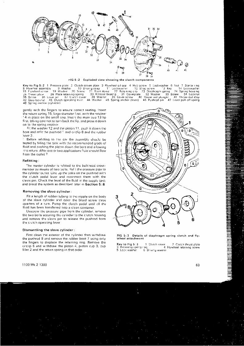
iTS A ^
i l " P40 4t 42
r l G 5 : 2 E x p l o d e d v i e w s h o w i n g t h e c l u t c h c o m p o n e n t s
K e y t o F i g 5 : 2 l P r e s s u r e p l a t e 2 C l u t c h d r i v e n p l a t e 3 F l y w h e e l o r l s e a l 4 H u b s c r e w 5 L o c k w a s h e r O N u l T S t a r t e r r i n g8 F l y w h e e l a s s e m b l y 9 W a s h e r 1 0 D r i v i n g s t r a p 1 1 L o c k w a s h e r 1 2 S t r a p s c r e w 1 3 K e y 1 4 L o c k w a s h e r1 5 F l y w h e e l s c r e w 1 9 W a s h e r 2 O S c r e w 2 1 R i v e t d o w e l 2 2 R e t a i n i n g c l i p 2 3 D i a p h r a g m s p r i n g 2 4 S p r i n g h o u s i n g2 5 l h r u s t p l a t e 2 6 P l a t e r e t a r n r n g s p r n g 3 0 R e l e a s e b e a r i n g 3 1 C o v e r p l a t e 3 2 W a s h e r 3 3 S c r e w 3 4 L o c k n u t35 Screw 36 Lever p in 37 C lu tch cover 38 Washer 39 Cover sc rew 40 Throw out p lunger 4 ' l Throw-out s top42 Stop locknut 43 C lu tch opera t ing lever 44 Washer 45 Spr ing anchor ( lever ) 46 Pushrod p in 47 Lever pu l l -o f f spr ing4 8 S p r i n g a n c h o r ( c y l i n d e r )
gen t l y w i t h t he f i nge rs t o ensu re co r rec t sea t i ng . I nse r tt he re tu rn sp r i ng 15 , l a rge d i ame te r f i r s t , w i t h t he re ta i ne r1 4 i n p l a c e o n t h e s m a l l e n d . l n s e r t t h e m a i n c u p 1 3 l i pf i r s t , t ak i ng ca re no t t o t u rn back t he l i p , and p ress i t downon t o t he sp r i ng re ta i ne r .
F r t t h e w a s h e r 1 2 a n d t h e o i s t o n 1 1 . p u s h i t d o w n t h ebo re and re f i t t he push rod 1 and c i r c l i p 8 and t he rubbe rboot 2.
Be fo re r e f i t t i ng t o t he ca r t he assemb ly shou ld betes ted by f i l l i ng t he t ank w i t h t he recommended g rade o lf l u i d and push ing t he p i s t on down t he bo re and a l l ow rngi t t o r e tu rn . A f t e r one o r two aoo l i ca t i ons f l u i d shou ld f l owf rom the ou t l e t 7 .
R e f i t t i n g :
The mas te r cy l i nde r i s r e f i t t ed t o t he bu l khead c ross -member by means o f two bo l t s . Re f i t t he p ressu re p i pe t othe cy l i nde r ou t l e t . L i ne up t he yoke on t he push rod w i t hthe c l u t ch peda l l eve r and reconnec t t hem w i t h t hec lev i s p i n . Check t he l eve l o f t he f l u i d i n t he supp l y t ankand bleed the system as descr ibed later rn Sect ion 5 :6.
Remov ing t he s l ave cy l i nde r :
F i t a l eng th o f r ubbe r t ub ing t o t he n i pp le on t he bodyo f t he s l ave cy l i nde r and open t he b l eed sc rew th reequa r te r s o f a t u rn . Pump the c l u t ch peda l un t i l a l l t hef l u i d has been t r ans fe r red i n t o a c l ean con ta i ne r .
Unsc rew the p ressu re p i pe f r om the cy l i nde r , r emovethe two bo l t s secu r i ng t he cy l i nde r t o t he c l u t ch hous ingand remove the c levis p in to re lease the pushrod f romthe c l u t ch ope ra t i ng l eve r .
D i s m a n t l i n g t h e s l a v e c y l i n d e r :
F i r s t c l ean t he ex te r i o r o f t he cy l i nde r t hen w t t hd rawthe push rod 8 and remove t he rubbe r boo t 7 us rng on l yt he f i nge rs t o d i sp l ace t he re ta i n i ng r i ng . Remove t hec i r c l i p 6 and w i t hd raw the p i s t on 4 , p i s t on cup 3 , cupf i l l e r 2 and t he re tu rn sp r i ng i n t ha t o rde r .
1 100 Mk 2 1300
F I G 5 : 3 D e t a i l s o f d i a p h r a g m s p r i n g c l u t c h a n d f l y -w h e e l a t t a c h m e n t
K e y t o F i g 5 ; 3 1 C l u t c h c o v e r 2 C l u t c h t h r u s t p l a t e3 R e t a i n i n g s p r i n g r i n g 4 F l y w h e e l r e t a j n i n g s c r e w5 L o c k w a s h e r 6 D r i v i n g w a s h e r
63
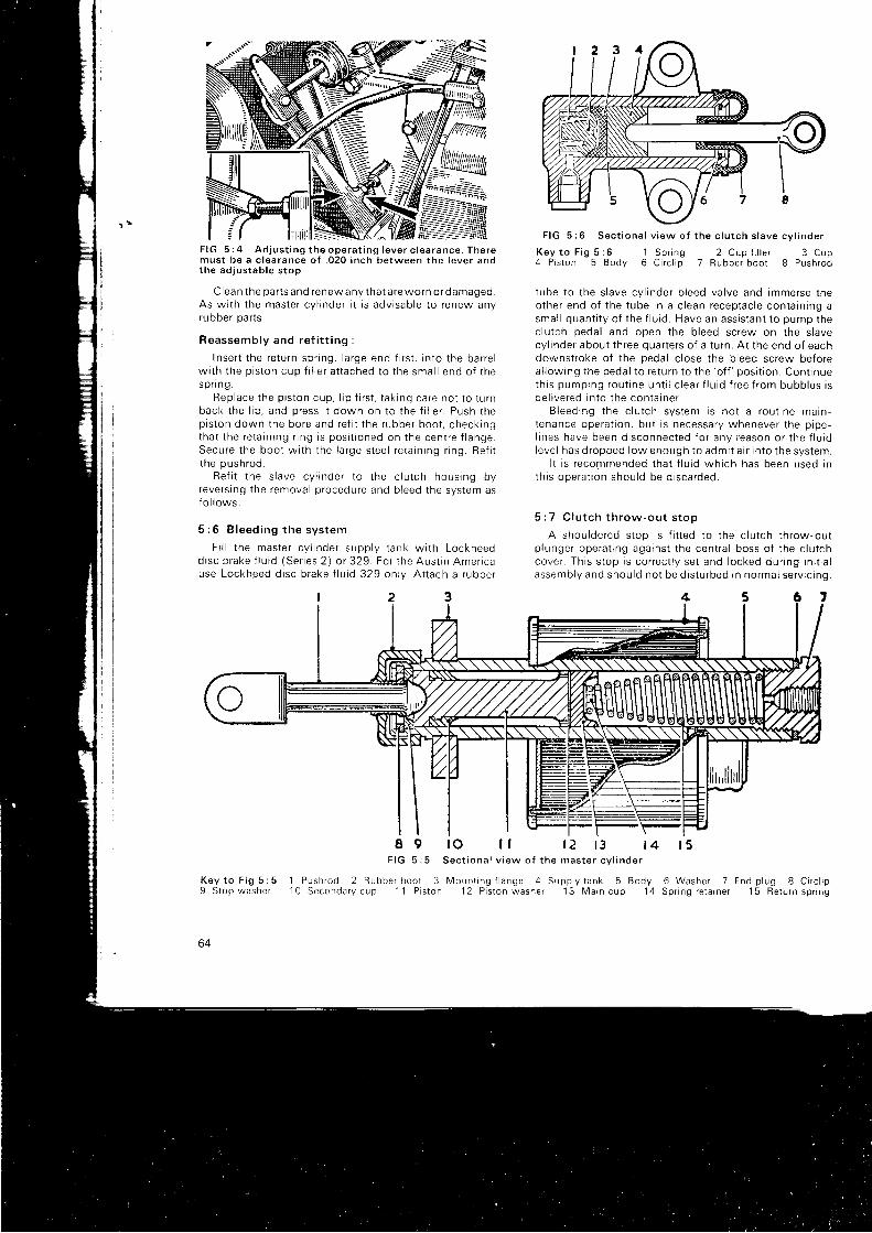
F I G 5 : 6 S e c t i o n a l v i e w o f t h e c l u t c h s l a v e c v l i n d e r
F I G 5 : 4 A d j u s t i n g t h e o p e r a t i n g l e v e r c l e a r a n c e . T h e r emus t be a c l ea rance o f . 020 i nch be tween t he l eve r andthe ad jus tab le s t op
C lea n t he pa r t s and renew any t ha t a re wo rn o r d amaged .As w i t h t he mas te r cy l i nde r i t i s adv i sab le t o r enew anyrubber Darts.
Reassemb ly and re f i t t i ng :
I nse r t t he re tu rn sp r i ng , l a rge end f i r s t , i n t o t he ba r re lw i t h t he p i s t on cup f r l l e r a t t ached t o t he sma l l end o f t hesp r i ng .
Rep lace t he p i s t on cup , l i p f i r s t , t ak i ng ca re no t t o t u rnback t he l i p , and p ress i t down on t o t he f i l l e r . Push t hep i s t on down t he bo re and re f i t t he r ubbe r boo t , check ingtha t t he re ta i n i ng r i ng i s pos i t i oned on t he cen t re f l ange .Secu re t he boo t w i t h t he l a rge s tee l r e ta i n i ng r i ng . Re f i tt he push rod .
Re f i t t he s l ave cy l i nde r t o t he c l u t ch hous ing byreve rs i ng t he remova l p rocedu re and b l eed t he sys tem asf o l l ows :
5 : 6 B leed ing t he sys tem
F i l l t he mas te r cy l i nde r supp l y t ank w i t h Lockheedd i sc b rake f l u i d (Se r i es 2 ) o r 329 . Fo r t he Aus t i n Amer i cause Lockheed d i sc b rake f l u i d 329 on l v . A t t ach a r ubbe r
K e y t o F i g 5 : 64 P i s t o n 5 B o d y
1 S p r i n g 2 C u p { i l l e r 3 C u p6 C i r c l i p 7 R u b b e r b o o t 8 P u s h r o d
I 9 r O l l 1 2 t 3 t 4F I G 5 : 5 S e c t i o n a l v i e w o f t h e m a s t e r c y l i n d e r
1 P u s h r o d 2 R u b b e r b o o l 3 M o u n t i n g f l a n g e 4 S u p p l y t a n k 5 B o d y1 0 S e c o n d a r y c u p 1 1 P i s t o n 1 2 P i s t o n w a s h e r 1 3 M a r n c u p 1 4
t ube t o t he s l ave cy l i nde r b l eed va l ve and immerse t heo the r end o f t he t ube i n a c l ean recep tac l e con ta i n i ng asma l l quan t i t y o f t he f l u i d . Have an ass i s t an t t o pump thec lu t ch peda l and open t he b l eed sc rew on t he s l avecv l i nde r abou t t h ree qua r t e r s o f a t u rn . A t t he end o f eachdownstroke of the pedal c lose the bleed screw beforea l l ow ing t he peda l t o r e tu rn t o t he
' o f f ' pos i t i on . Con t i nueth i s pump ing rou t i ne un t i l c l ea r f l u i d f r ee f r om bubb les r sde l i ve red i n t o t he con ta i ne r .
B leed ing t he c l u t ch sys tem i s no t a r ou t i ne ma in -t enance ope ra t i on , bu t i s necessa ry wheneve r t he p i pe -l i nes have been d i sconnec ted f o r any reason o r t he f l u i dl eve l has d ropped l ow enough t o adm i t a i r i n t o t he sys tem.
I t i s r ecommended t ha t f l u i d wh i ch has been used I nth i s ope ra t i on shou ld be d i sca rded .
5 : 7 C lu t ch t h row-ou t s t op
A shou lde red s top i s f i t t ed t o t he c l u t ch t h row ,ou tp l unge r ope ra t i ng aga ins t t he cen t ra l boss o f t he c l u t chcove r . Th i s s t op i s co r rec t l y se t and l ocked du r i ng i n r t i a lassemb ly and shou ld n01 be d i s t u rbed i n no rma l se rv i c i ng .
r 5
6 W a s h e r 7 E n d p l u g 8 C i r c l i pS p r r n g r e t a r n e r 1 5 R e t u r n s p r r n g
K e y t o F i g 5 ; 59 S t o p w a s h e r
64
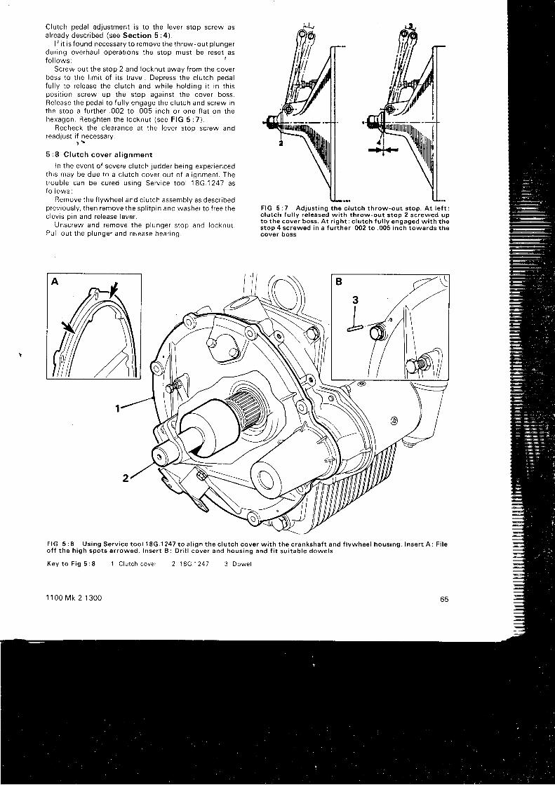
Clutch pedal adjustment is to the lever stop screw asa l r eady desc r i bed ( see Sec t i on 5 : 4 ) .
l f i t is found necessary to remove the throw-out p lungerdur ing overhaul operat ions the stop must be reset asfo l l ows : I
Screw out the stop 2 and locknut away f rom the coverboss to the l imi t of i ts t ravel . Depress the c lutch pedalf u l l y t o r e l ease t he c l u t ch and wh i l e ho ld i ng i t i n t h i sposi t ion screw up the stop against the cover boss.Re lease t he peda l t o f u l l y engage t he c l u t ch and sc rew i nthe s top a f u r t he r . 002 t o .005 i nch o r one f l a t on t hehexagon . Re t rgh ten t he l ocknu t ( see F IG 5 :7 ) .
Recheck t he c l ea rance a t t he l eve r s t op sc rew andreadjust i f necessary.
) r
5 : 8 C l u t c h c o v e r a l i g n m e n t
I n t he even t o f seve re c l u t ch j udde r be ing expe r i encedth i s may be due t o a c l u t ch cove r ou t o f a l i qnmen t . Thet roub le can be cu red us i ng Se rv i ce t oo l 18G.1247 asf o l l o w s :
Remove t he f l ywhee l and c l u l ch assemb ly as desc r i bedp rev ious l y , t hen remove t he sp l i t p i n and washe r t o f r ee t hec lev i s p i n and re l ease l eve r .
Unsc rew and remove t he p l unge r s t op and l ocknu t .Pu l l ou t t he p l unge r and re l ease bea r i ng .
F I G 5 : 7 A d j u s t i n g t h e c l u t c h t h r o w - o u t s t o p . A t l e f t :c l u t c h f u l l y r e l e a s e d w i t h t h r o w - o u t s t o p 2 s c r e w e d u pt o t h e c o v e r b o s s . A t r i g h t : c l u t c h f u l l y e n g a g e d w i t h t h es top 4 screwed in a f u r ther .002 to .005 inch towards thecover ooss
F I G 5 : 8 U s i n g S e r v i c e t o o l 1 8 G . 1 2 4 7 t o a l i g n t h e c l u t c h c o v e r w i t h t h e c r a n k s h a f t a n d f l y w h e e l h o u s i n g . I n s e r t A : F i l eo f f t h e h i g h s p o t s a r r o w e d . I n s e r t B : D r i l l c o v e r a n d h o u s i n g a n d f i t s u i t a b l e d o w e l s
K e y t o F i g 5 : 8
1 1 0 0 M k 2 1 3 0 0
I C lu tch cover 2 1 8 G . 1 2 4 7 3 D o w e l
65

See that a l l the parts are c lean and then apply someengineers blue to the c lutch cover register .
Re fe r t o F IG 5 :8 . I nse r t t he t oo l 18G.1247 i n t o t hecover and ref i t the cover wi th the tool over the crankshaftlaper.
Push the cover against the f lywheel housing to seehow much m isa l i gnmen t t he re i s , wh i ch w i l l be shown onthe blueing when the c lutch cover is removed. Fi le downthe high spots as necessary.
Repeat th is procedure as required unt i l the covercontacts the f lywheel housing wi thout force. When th iscorrect a l ignment has been obtained, secure the coverwi th two reta in ing bol ts.
Now dr i l l two diametr ical ly opposi te holes through thecover and f lywheel housing f langes wi th a No, 40 dr i l l asshown in inset B. Remove the cover and the tool .
Assemb l i ng :
Lub r i ca te t he re l ease bea r i ng p l unge r .w i t h a l i n l egraphi te grease and ref i t the parts in the reverse order ofremoval but only loosely t rghten the cover reta in ing bol ts.
Fi t two dowels 2.49 " 21 mm into the newly dr i l ledholes to reta in the cover a l ignment. These musl be aninter ference f i t and needle ro l lers f rom a bear ing are verysui table for the purpose.
Tighten the cover reta in ing bol ts and complete theinstal lat ion.
Check, and adjust i f necessary, the throw-out stop andreturn stop adjustments.
5 : 9 F a u l t d i a g n o s i s
(a) Drag or sP in
1 Oil or grease on driven plate l inings2 Leaking master cyl inder, slave cyl inder or piping3 Driven plate hub binding on spl ines4 Distorted driven plate5 Warped or damaged Pressure Plate6 Broken driven Plate l inings7 Air in the clutch hydraul ic system
(b) Fierceness or snatch
1 Check 1 , 2 , 4 and 5 in (a )2 Worn clutch l inings
( c ) S l i p
1 Check 1 in (a ) and 2 in (b )2 Weak diaphragm spring3 Seized piston in slave cyl inder4 Operating lever stop has no clearance
(d) Judder
1 Check 1 and 4 in (a)2 Pressure plate incorrectly f i t ted to spring housing3 Contact area of driven plate l inings unevenly distr ibuted4 Faulty rubber mountings
(e) T ick o r knock
1 Badlv worn drlven plate hub spl ines2 Worn release bearing3 Faulty drive pinion on starter4 Elongated holes in spring housing5 Defective drive straps
66
CHAPTER 6
SYNCH ROM ESH TRANSM ISSION
6 : 1 Desc r i p t i on6 : 2 D i s m a n t l i n g t r a n s m i s s i o n6 : 3 S e r v i c i n g t h i r d m o t i o n s h a f t6 : 4 R e a s s e m b l i n g t r a n s m i s s i o n6 : 5 Se rv i c i ng t he d i f f e ren t i a l assemb lv
6 : 1 Desc r i p t i on
The t ransmission gearbox f i t ted to a l l the cars whicha re cove red by t h i s manua l has f ou r f o rwa rd speeds ano areverse selected by a remote contro l gearshi f t lever. Baulkr i ng - t ype synch romesh engagemen t i s p rov i ded onei ther three or four forward speeds. Two dl f ferent tvpes ofgea r change mechan i sm a re used and i t w i l l be conven ien rt o desc r i be t he p rocedu res f o r se r v i c i ng t he ea r l y t ypef i r s t and t hose changes needed f o r t he l a t e r , s i ng leope ra t i ng rod , t ype i n t he second pa r t o f t h i s Chao te r .
The exp loded v i ew o f t he t r ansm iss i on g i ven i n F IG6 :1 shows c l ea r l y t he l ayou t o f t he i n t e rna l componen tswhen seen f rom the rear. and reference to th is d iaoramw i l l ass i s t i n f o l l ow tng a sho r t desc r i p t t on o f t he gea rboxope ra t t on .
The d r i ve f r om the c l u t ch i s t aken t h rough t he p r ima rygea r 40 t o t he i d l e r gea r 43 , wh i ch d r i ves t he f i r s t mo r ronsha f t gea r 45 and t he f i r s t mo t i on sha f t 61 ro wh i ch r t i ssp l i ned . The sma l l gea r on t h i s sha f t engages t he l a rges tgear in the laygear assembly 54. The th i rd mot ion shaf t 65ca r r i es t he gea r and synch romesh assemb l i es 6g t o 95 .i t s r i gh thand end runn ing f r ee l y i n t he ro l l e r bea r i ng 62at the end of the f i rs t mot ion shaf t , whi le the other. lef t -hand , end i s suppo r ted rn t he ro l l e r bea r i ng 66 . Sp l i ned t o
1 1 0 0 M k 2 1 3 0 0
6 : 6 D i sman t l i ng t he gea rbox w i t h l a t e r t ypechange
6 : 7 Gea r change remo te con t ro l6 : 8 F a u l t d i a g n o s i s
t h i s l e f t hand end o f t he t h i r d mo r i on sha f t r s t he f i na l d r i vep in i on 90 wh i ch engages w i t h t he d r i ve gea r i n t hed i f f e ren t i a l assemb ly and wh tch i n t u rn d r i ves t he sha f t scoupled to the f ront wheels.
No ma in tenance i s r equ i r ed o the r t han regu la r a t t en t i onto t he o i l l e ve l i n t he eng ine / t r ansm iss i on un i t . The g reasen ipp le ' 1 52 , by wh i ch t he gea rchange remo te con t ro lshaf t is lubr icated through the di f ferent ia l cover. requiresat tentron at major overhaul per iods only when greaseon l y shou ld be used .
6 : 2 D i s m a n t l i n g t h e t r a n s m i s s i o n
Re fe r t o F IG 6 :1 . Remove t he t r ansm iss i on cas ingf r om the c rankcase as desc r i bed i n Chap te r 1 , t hen w i t h -d raw the i d l e r gea r 43 and t he t h rus t washe rs 44 f r om thec rankcase . Spec ia l t oo l No . 18G.581 w i l l be needed f o rex t r ac t i ng t he i d l e r gea r bea r i ngs 20 .
Remove t he d i f f e ren t i a l assemb ly as desc r i bed l a t e r i nt h i s Chap te r ( see Sec t i on 6 :5 ) . W i t hd raw the reve rsede ten t p l ug 1 35 , sp r i ng 1 34 and p l unge r 1 33 o r t he reve rsel i gh t sw i t ch and p l unge r when f i t t ed . Remove t hese lec to r ope ra t i ng l eve r 122 and w i t hd raw the sha f t 120payrng at tent ion to t i te seal 1 21 and key 1 23. Remove thespeedometer bush secur ing screw and wtthdraw the bush
o t
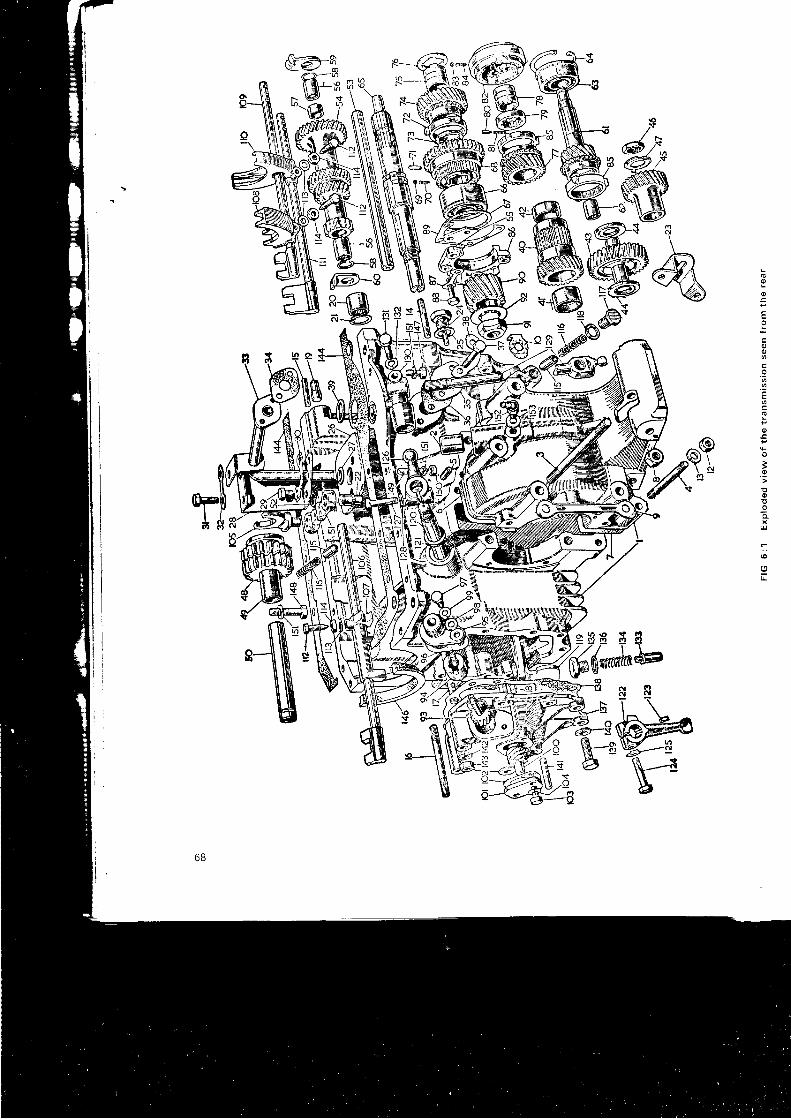
\
& oo
E
oo
tr'6
.2t
o
3o' t
o
aq
:
tr
Z - s f t RR - u T \-F;W@ \1----ru
@-
i€
68
ee;i n:glfi; ij: Fi:: n:iiEE;!;; ;. ,i:iF-ie:;A€:* . ; ; : * ; i . l iE: ; i i ; :: i N : = : @ ; : = X : o O - :
: ' i " : * ; R i ; ; c c > e I
; : - g:s; i i ' " ls; ; t r= ; p: > ^ : o ^ r l X - 9 - ; r - : i
gtgi ;*r ! i : ;sr ; ; l : , : 5:;: l , i :t r l* ' i=5,{*:i€ =e -5; F;g€ i t===t-I: j ;
ffiifs*:!i#n':ss:e i = R o = , : : l e + 5 ; g g ! E :
;;!tiiii4iiA;;*;:;! : i g = g B i = 3 f ; i I = 1 = i
*c;- -rjl;::;;==;; i;=*ii;€i:';5:;i; i,5i':c lAa j : s** i *3 i l= i . i ;;:;-'* f:;-:j;::E!;$;$:irt:;*:*;; :i*r:;: s=;* i : - ; i I3 9:!==* ; rit5f ilF,E:;ff;93ii!F:E;i:ri:';Ei=!g:'1,gif il5$=,lu=i':=;iF;r:;t:;*;:=r;;iit,[:i'3it;; j*:l Irt
=i=; ;= ; i
ll:ffg,g=iP;is=rSsg!i9 l : rnsssDassB p : : F I I 3 f
assemb ly and t he p i n i on 93 t o gg . Remove t he re ta i n i ngp la te and speedome te r gea r 100 t o 104 .
Remove t he rad ia to r , cow l rng , moun t i ng b racke t andspace r as desc r i bed i n Chap te r 4 . Remove t he t r ansm is -s i on f r on t cove r 1 37 . Remove t he sc rews 31 and 37 anothe o i l suc t i on p i pe 33 wh i ch shou ld be w i t hd rawnf rom the s t r a tne r 26 , no t i ng t he pape r washe r 34 . Ren rovethe se lec to r i n t e r l ock i ng a rm .
Ex t rac t t he c i r c l i p 64 and w i t hd raw the f i r s t mo t i onsha f t r o l l e r bea r i ng us i ng se rv i ce t oo l 18G.705 anoadap to r 18G.705C . Us ing t he se lec to r sha f t s l ock f i r s t andthi rd gears together, re lease the locking washers 4J anoremove t he f i r s t mo t i on sha f t nu t 46 and gea r 45 . Removethe f i na l d r r ve gea r nu t 91 , washe r 92 and p i n i on 90 f r omthe t h r rd mo t i on sha f t 65 .
Re lease t he l ock i ng p l a tes and remove t he f ou rsecu r i ng sc rews B8 t o f r ee t he t h i r d mo t i on sha f t bea r i ngre ta i ne r 86 , no t i ng t he pack ing sh ims 8g .
Remove the layshaft and reverse shaf t locat ing plate 55and push t he l aysha f t ou t o f t he c l u t ch s rde o f t he cas ing .Remove t he l aygea r 54 and t he t h rus t washe rs 59 and 60 .
Unsc rew the p l ugs f r om the ou t s i de o f t he cas ino andex t rac t t he se lec to r r od i n t e r l ock i ng p l unge rs and sp " r i ngs1 1 5 a n d 1 1 6 .
Remove t he f i r s t mo t i on sha f t bea r i ng c i r c l i p 64 anow i t hd raw the bea r i ng and sha f t f r om the cas ing us i ngse rv i ce t oo l s 18G.284 and 18G.284B o r o the r su i t ab leex t rac to r . Remove t he se lec to r sc rew 1 12 and w i t hd rawthe fork rod 1 09 and the fork 1 08.
Re fe r t o F IG 6 :2 . To remove t he t h i r d mo t i on sha f tbea r i ng t he f o l l ow ing p rocedu re shou ld be used : D r i f tt he sha f t backwards as i nd i ca ted by t he a r row i n A un t r rthe specia l serv ice tool 1 can be inserted between rnef i r s t speed gea r 2 and t he bea r i ng 3 as i l l u s t r a teo rnd iag ram B . No te t ha t t he recessed f ace o f t he t oo l i st owa rds t he bea r i ng . Ca re fu l l y d r i f t t he sha f t ou t o f t hecas ing as i l l u s t r a ted i n d i ag ram C 10 f r ee t he bea r i ng 3from the web, taking care not to damage the selectorf o r ks i n t he ope ra t i on . Pu l l t he bea r i ng f r om the sha f t anol i f t the shaf t f rom the casing.
Remove t he o i l s t r a i ne r b racke t 2g comp le te w r tns t r a i ne r . Re lease t he f o r k 110 f r om i t s r od 11 1 and w i t h_draw both rod and fork. Remove the reverse gear shaf t 50,gear 48 and selector fork '1
05. Extract the detent spr ing' 1 16 and p l unge r 115 . Remove t he c i r c l i p 52 and l i f t o f f
t he reve rse gea r ope ra t l ng l eve r 51 .
6 : 3 Se rv i c i ng t he t h i r d mo t i on sha f tThree-speed synchromesh gearboxes :
Remove t he t h i r d mo t i on sha f t assemb ly as desc r i bedi n S e c t i o n 6 : 2 .
Remove t he f i r s t - speed gea r 68 , hub and bau l k r i ngf r om the rea r o f t he sha { t , and t he t op / t h i r d synch romesnhub B2 and bau l k r i ngs f r om the f r on t o f t he sha f t .
Remove t he f r on t t h rus t washe r by dep ress ing t hep lunge r and tw i s t i ng un t i l t he sp l i nes reg i s t e r w i t h t hoseon t he sha f t , t hen w i t hd raw the t h i r d - speed gea r 77comp le te w i t h need le r o l l e r bea r i ngs and t ake ou t t hep lunge r and sp r i ng .
Depress the'spr ing- loaded pegs, twist and remove tnesecond -speed gea r l ock i ng co l l a r 76 . S l i de o f f t he twosp l i t washe rs , pu l l o f f t he gea r 74 f r om the rea r o f t hesha f t and remove t he need le r o l l e r bea r i ngs f r om the i rJOU rna l s .
1 1 00 Mk 2 1 300
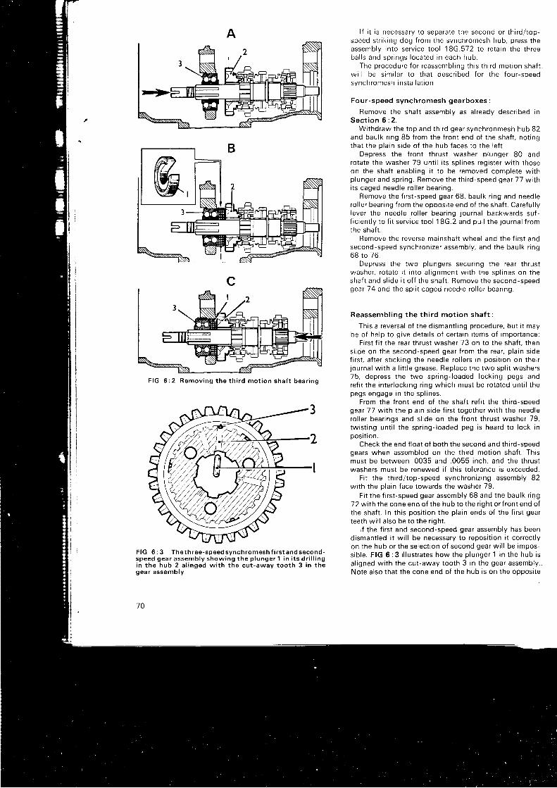
F I G 2 R e m o v i n g t h e t h i r d m o t i o n s h a f t b e a r i n g
F I G 6 : 3 T h e t h r e e - s p e e d s y n c h r o m e s h f i r s t a n d s e c o n d -s p e e d g e a r a s s e m b l y s h o w i n g t h e p l u n g e r 1 i n i t s d r i l l i n gi n t h e h u b 2 a l i n g e d w i t h t h e c u t - a w a y t o o t h 3 i n t h egear assembly
70
l f i t is necessary to separate the second or th i rd/ top-speed str ik ing dog f rom the synchromesh hub, press theassemb ly r n to se r v i ce t oo l 18G.572 t o r e ta i n t he t h reeba l l s and sp r i ngs l oca ted i n each hub .
The p rocedu re f o r r eassemb l i ng t h i s t h i r d mo t i on sha f tw i l l be s im i l a r t o t ha t desc r i bed f o r t he f ou r - speedsynch romesh i ns ta l l a t i on .
Fou r - speed synch romesh gea rboxes :
Remove the shaf t assembly as al ready descr ibed inSec t i on 6 : 2 .
W i t hd raw the t op and t h i r d gea r synch ronmesh hub 82and baulk r ing 85 f rom the f ront end of the shaf t , not ingthat the pla in s ide of the hub faces to the lef t .
Depress the f ront thrust washer p lunger 80 androtate the washer 79 unt i l i ts spl ines register wi th thoseon the shaf t enabl ing i t to be removed complete wi thp lunge r and sp r i ng . Remove t he t h i r d - speed gea r 77 w i t hi t s caged need le r o l l e r bea r i ng .
Remove t he f i r s t - speed gea r 68 , bau l k r i ng and need lerol ler bear ing f rom the opposi te end of the shaf t . Careful lylever the needle ro l ler bear ing journal backwards suf-f i c i en t l y t o f i t se r v i ce t oo l 18G.2 and pu l l t he j ou rna l f r omthe shaf t .
Remove the reverse mainshaft wheel and the f i rs t andsecond -speed synch ron i ze r assemb ly , and t he bau l k r i ng68 t o 76 .
Dep ress t he two p l unge rs secu r i ng t he rea r t h rus twashe r , r o ta te i t i n t o a l i gnmen t w i t h t he sp l i nes on t heshaft and s l ide i t of f the shaf t . Remove the second-speedgea r 7 4 and t he sp l i t caged need le r o l l e r bea r i ng .
Reassemb l i ng t he t h i r d mo t i on sha f t :
This a reversal of the dismant l ing procedure, but i t maybe of help to g ive detai ls of certa in i tems of importance:
First f i t the rear thrust washer 73 on to the shaf t . thens l i de on t he second -speed gea r f r om the rea r , p l a i n s i def i rst , af ter st ick ing the needle ro l lers rn posi t ion on their
l ou rna l w i t h a l i t t l e g rease . Rep lacd t he two sp l i t washe rs75 , dep ress t he two sp r i ng - l oaded l ock i ng pegs andref i t the inter locking r ing which must be rotated unt i l thepegs engage in the spl ines.
From the f ront end of the shaf t ref i t the th i rd-speedgea t
- 77 w i t h t he p l a i n s i de f i r s t t oge the r w i t h t he need le
ro l l e r bea r i ngs and s l i de on t he f r on t t h rus t washe r 79 ,twist ing unt i l the spr ing- loaded peg is heard to lock inposrt ron.
Check the end f loat of both the second and th i rd-speedgears when assembled on the th i rd mot ion shaf t . Thrsmust be between .0035 and .0055 inch, and the thrustwashers must be renewed i f th is to lerance is exceeded.
Fi t the th i rd/ top-speed synchroniz ing assembly 82with the pla in face towards the washer 79.
Fi t the f i rs t -speed gear assembly 68 and the baulk r ing72 wi th the cone end of the hub to the r ight or f ront end ofthe shaf t . In th is posi t ion the pla in ends of the f i rs t gearteeth wi l l a lso be to the r ight .
l f the f i rs t and second-speed gear assembly has beendismant led i t wi l l be necessary to reposi t ion i t correct lyon the hub or the select ion of second gear wi l l be impos-s i b l e . F IG 6 :3 i l l u s t r a tes how the p l unge r 1 i n t he hub i sal igned wi th the cut-away tooth 3 in the gear assembly.Note also that the cone end of the hub is on the opposi te
),'fl45Yt'tu*///,
7%
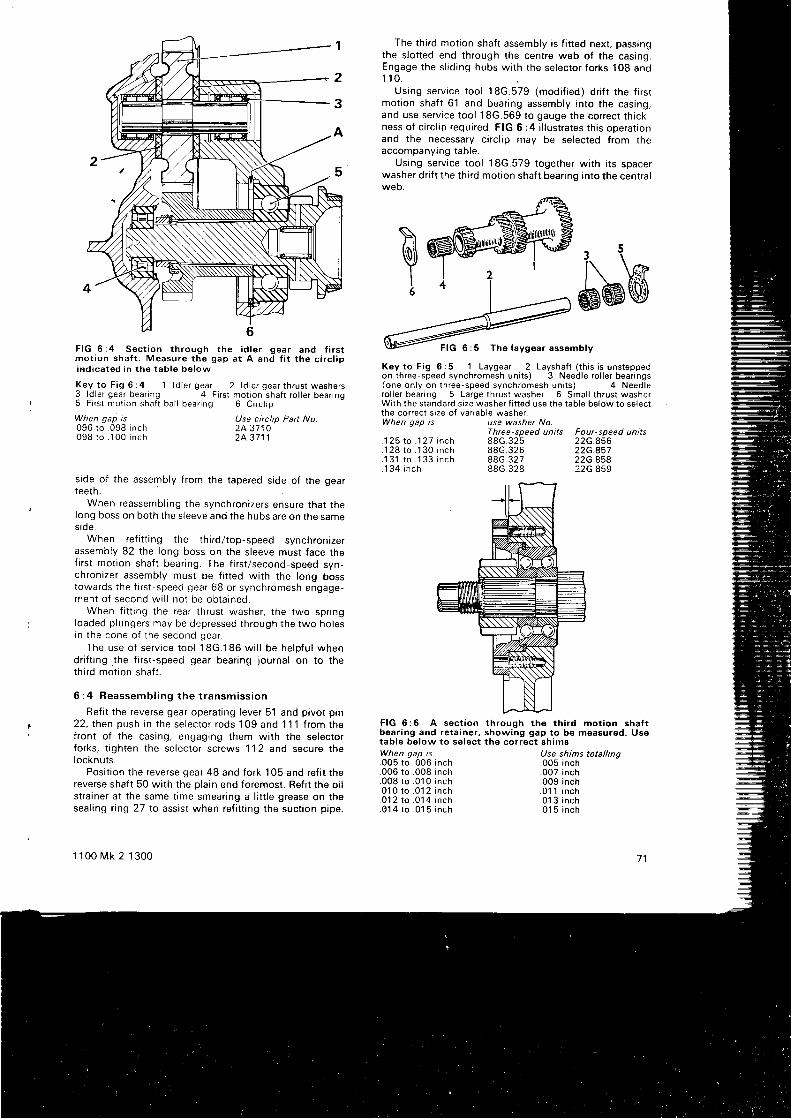
The th i rd mot ion shaf t assembly is f i t ted next , passingthe s lot ted end through the centre web of the casing.Engage the s l id ing hubs wi th the selector forks 108 and1 1 0 .
Using serv ice tool 18G.579 (modi f ied) dr i f t the f i rsrmot ion shaf t 61 and bear ing assembly into the casing,and use serv ice tool 1 8G.569 to gauge the correct th ick-ness of c i rc l ip required. FIG 6:4 i l lustrates th is operat ionand the necessary c i rc l ip may be selected f rom theaccompanying table,
Using serv ice tool 18G.579 together wi th i ts spacerwasher dnf t the th i rd mot ion shaf t bear ing into the centra lweo.
eMWThe laygear assemblyF I G 6 : 4 S e c t i o n t h r o u g h t h e i d l e r g e a r a n d f i r s t
mot ion shaf t . Measure the gap a t A , and f i t the c i rc l ipi n d i c a t e d i n t h e t a b l e b e l o w
Key to F ig 6 :4 1 ld le r gear 2 ld le r gear th rus t washers3 ld le r gear bear ing 4 F i rs t mot ion shaf t ro l le r bear ing5 F i rs t mor ion shaf t ba l l bear ing 6 C i rc l ip
When gap is. 0 9 6 t o . 0 9 8 i n c h. 0 9 8 t o . 1 0 0 i n c h
Use circlip Patt No.2A.37102A.3711
side of the assembly f rom the tapered s ide of the gearteeth.
When reassembl ing the synchronizers ensure that thelong boss on both the s leeve and the hubs are on the sames ide .
When ref i t t ing the rh i rd/ top-speed synchronizerassembly 82 the long boss on the s leeve must face tnef i rst mot ion shaf t bear ing. The f i rs t /second-speed syn-chronizer assembly must be f i t ted wi th the long bosstowards the t r rst -speed gear 68 or synchromesh engage-men t o f second w i l l no t be ob ta i ned .
When f i t t ing the rear thrust washer, the two spr ingloaded plungers may be depressed through the two holesin the cone of the second gear.
The use of serv ice tool 18G.186 wi l l be helpfu l whendr i f t ing . the f i rs t -speed gear bear ing journal on to thethi rd mot ion shaf t .
6 : 4 Reassemb l i ng t he t r ansm iss i on
Ref i t the reverse gear operat ing lever 51 and pivot p in22, then push rn the selector rods 109 and 1"1 1 f rom thefront of the casing, engaging them with the selectorforks, t ighten the selector screws ' l 12 and secure thelocknuts.
Posi t ion the reverse gear 48 and fork 105 and ref i t thereverse shaf t 50 wi th the pla in end foremost. Ref i t the oi ls t ra iner at the same t ime smear ing a l i t t le grease on theseal ing r ing 27 to assist when ref i t t ing the suct ion pipe.
1 1 0 0 M k 2 1 3 0 0
use washer No.Three speed units Four-speed units8 8 G . 3 2 5 2 2 G . 8 5 6
22G.45722G.85822G.859
88G.32688G.32788G 328
FIG 6:6 A sect ion through th€ th i rd mot ion shaf tboar ing and reta iner, showing gap to be moasured. Usetable below to select the correct shimsWhen gap is005 to .006 inch006 to .008 inch008 t o . 010 i nch010 t o . 01 2 i nch0 1 2 t o . 0 1 4 i n c h014 t o . 01 5 i nch
Use shims totalling.005 inch.007 inch.009 inch. 0 1 1 i n c h. 0 1 3 i n c h.01 5 inch
7 1
S'ajI6
Key to F ig 6 :5 1 Laygear 2 Layshaf i ( th is i s uns teppedon th ree-speed synchromesh un i ts ) 3 Need le ;o l le r bear ings(one on ly on lh ree-speed synchromesh un i ts ) 4 Need lero l le r bear ing 5 Large th rus t washer 6 Smal l th rus t washerWi th the s tandard s ize washer f i t ted use the tab le be low to se lec tthe cor rec t s ize o f var iab le washer .When gap is
. 1 2 5 t o . 1 2 7 i n c h
. 1 2 8 t o . 1 3 0 i n c h
. 1 3 1 t o . 1 3 3 i n c h
. 1 3 4 i n c h
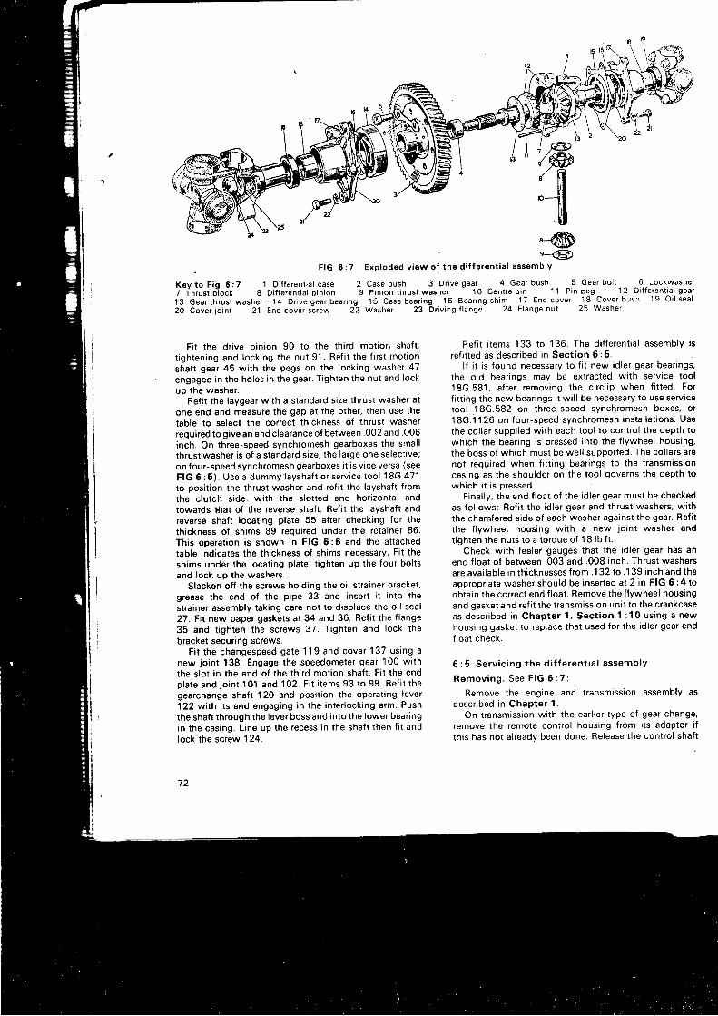
'@e-@
. F I G 6 : 7 E x p l o d e d v i a w o f t h e d i f f e r e n t i a l a s s e m b l y
K e y t o F i g 6 : 7 l D i f f e r e n t i a l c a s e 2 C a s e b u s h 3 D r i v e g e a r - ^ 4 G e a r b u s h 5 G e a r b o l t 6 L o c k w a s h e l
7 T h r u s t b j o c k 8 D i f f e r e n t i a l p i n i o n 9 P i n i o n t h r u s t w a s h e r -
1 0 C e n t r e p i n 1 1 P i n p e g 1 2 D i f f e r e n t i a l g e a r
13 Gear th rus t washer 14 Dr ive gear bear ing 15 Case bear ing 16 Bear ing sh im 17 End cover 18 Cover bush 19 Oi l sea l
20 Cover jo in t 21 End cover s i rew 2 i Washer 23 Dr iv ing f lange 24 F lange nu t 25 Washer
Fit the drive pinion 90 to the third motion shaft,t ightening and locking the nut 91 . Refi t the f irst motionshaft gear 45 with the pegs on the locking washer 47engaged in the holes in the gear. Tighten the nut and lockup the washer.
Refi t the laygear with a standard size thrust washer atone end and measure the gap at the other, then use thetable to select the correct thickness of thrust washerrequired to give an end clearance ol between .002 and .006inch. On three-speed synchromesh gearboxes the smallthrust washer is of a standard size, the large one selective;on four-speed synchromesh gearboxes i t is vice versa (seeFIG 6 :5 ) . Use a dummy1ayshaf t o r serv ice too l 18G.471to posit ion the thrust washer and ref i t the layshaft fromthe clutch side, with the slotted end horizontal andtowards rhat of the reverse shaft. Refi t the laYshaft andreverse shaft locating plate 55 after checking for thethickness of shims 89 required under the retainer 86.This operation is shown in FIG 6:6 and the attachedtable indicates the thickness of shims necessary. Fit theshims under the locating plate, t ighten up the four boltsand lock up the washers.
Slacken off the screws holding the oi l strainer bracket,grease the end ol the pipe 33 and insert i t into thestrainer assembly taking care not to displace the oi l seal27. Fit new paper gaskets at 34 and 36. Refi t the f lange35 and t ighten the screws 37. Tighten and lock thebracket securing screws.
Fit the changespeed gate 1 1 9 and cover 1 37 using anew joint 138. Engage the speedometer gear 100 withthe slot in the end of the third motion shaft. Fit the endplate and joint 101 and 102. Fit i tems 93 to 99. Refi t thegearchange shaft 120 and posit ion the operating lever122 with i ts end engaging in the interlocking arm. Pushthe shaft through the level boss and into the lower bearingin the casing. Line up the recess in the shaft then f i t andlock the screw 1 24.
72
Ref i t i tems 133 to 136. The di f ferent ia l assembly isref i t ted as descr ibed in Sect ion 6:5.
l f i t is found necessary to f i t new id ler gear bear ings,the old bear ings may be extracted wi th serv ice tool18G.581 , af ter removing the c i rc l ip when f i t ted Forf i t t ing the new bear ings i t wi l l be necessary to use serv icetool 18G.582 on three-speed synchromesh boxes, or18G.1126 on four-speed synchromesh instal lat ions. Use
the col lar suppl ied wi th each tool to contro l the depth to
which the bear ing is pressed into the f lywheel housing,
the boss of which must be wel l supported. The col lars arenot required when f i t t ing bear ings to the t ransmissioncasing as the shoulder on the tool governs the depth towhich i t is oressed.
Final ly , the end f loat of the id ler gear must be checkedas fo l lows: Ref i t the id ler gear and thrust washers, wi th
the chamfered s ide of each washer against the gear. Ref i t
the f lywheel housing wi th a new jo int washer and
t ighten the nuts to a torque of 18 lb f t .Check wi th feeler gauges that the id ler gear has an
end f loat of between .003 and .008 inch. Thrust washers
are avai lable in th icknesses f rom .132 to .139 inch and theappropr iate washer should be inserted at 2 in FIG 6:4 toobtain the correct end f loat . Remove the f lywheel housing
and gasket and ref i t the t ransmission uni t to the crankcaseas desc r i bed i n Chap te r 1 , Sec t i on 1 :10 us i ng a new
housing gasket to replace that used for the id ler gear end
f loat check.
6 :5 Se rv i c i ng t he d i f f e ren t i a l assemb ly
R e m o v i n g . S e e F I G 6 : 7 .
Remove the engine and t ransmission assembly asdescr ibed in Chapter 1.
On t ransmission wi th the ear l ier type of gear change,
remove the remote contro l housing f rom i ts adaptor i f
th is has not a l readv been done. Release the contro l shaf t
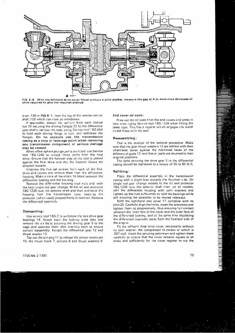
F I G 6 : 8 W i t h t h e l e f t h a n d d r i v e c o v e r f i t t e d w i t h o u t a j o i n t w a s h e r , m e a s u r e t h e g a p a t A t o d e t e r m i n e t h i c k n e s s o fs h i m r e q u i r e d t o g i v e t h e r e q u i r e d p r e l o a d
l e ve r , 130 i n F IG 6 : 1 , f r om the t op o f t he remo te con t ro lsha f t 129 wh i ch can now be w i t hd rawn .
l f app l i cab le , ex t r ac t t he sp l i t p i n f r om each s l o t t ednu t 24 secu r i ng t he d r i v i ng f l anges 23 t o t he d r f f e ren t i a lgea r sha f t s , r emove t he nu t s , us i ng Se rv i ce t oo l 1 8G .669to ho ld each d r i v i ng f l ange i n t u rn , and w i t hd raw thef l anges . On no accoun t use t he t r ansm iss i oncas ing as a s t op o r l eve rage po in t when remov ingany t r ansm iss i on componen t o r se r i ous damagemay be caused .
When of fset sphere plunge jo ints are f i t ted, use Servicetoo l 18G.1240 t o un lock t hese j o i n t s f r om the f i na l
d r i ve . Ensu re t ha t t he f u l c rum s i de o f t he t oo l i s p l aced
aga ins t t he f i na l d r i ve and t ha t i he hammer b l ows a redirected inwards.
Unscrew the f ive set screws f rom each of the f inald r i ve end cove rs and remove t hem f r om the d i f f e ren t i a lhous ing . Make a no te o f t he sh ims 16 f i t t ed be tween t hed i f f e ren t i a l bea r i ng and t he hous ing .
Remove t he d i f f e ren t i a l hous ing s tud nu t s and , w t t hthe l a t e r s i ng le r od gea r change , f i t t he o i l sea l p ro tec to r18G.1236 ove r t he se lec to r sha f t and t hen w i t hd raw thehous ing f r om the t r ansm iss i on case , keep ing t hep ro tec to r (when used ) p ressed f i rm l y i n pos i t i on . Removethe di f ferent ia l assembly.
D i sman t l i ng :
Use se rv i ce t oo l 18G.2 t o w i t hd raw the two d r i ve gea rbea r i ngs
' 14 . Knock back t he l ock i ng p l a te t abs andremove t he s i x bo l t s secu r i ng t he d r i v i ng gea r 3 t o t hecage and separate them af ter marking each to ensurecorrect reassembly. Extract the di f ferent ia l gear '1
2 andth rus t washe r 13 .
Tap ou t t he p i n peg 1 1 t o r e l ease t he p i n i on cen t re p i n10 , t he t h rus t b l ock 7 , p i n i ons B and t h rus t washe rs 9 .
1 1 0 0 M k 2 1 3 0 0
End cove r o i l sea l s :
Pr ise out the oi l seals f rom the end covers and press in
new ones , us i ng Se rv i ce t oo l 18G.1238 when f i t t i ng t hela tes t t ype . Th i s has a r eg i s t e r wh i ch engages t he wa te rsh ie l d f i t t ed w i t h t he sea l .
Reassemb l i ng :
This is the reversal of the removal procedure. Makesure that the gear thrust washers 13 are ref i t ted wi th theirchamfered bores agaiost the machined faces of thed i f f e ren t i a l gea rs12 , and t ha t a l l pa r t s a re r e tu rned t o t he i ro r i g i na l pos i t i ons .
The bol ts secur ing the dr ive gear 3 to the di f ferent ia lcasing should be t ightened to a torque of 55 to 60 lb f t .
Re f i t t i ng :
Place the di f ferent ia l assembly in the t ransmissioncas ing w i t h a s l i gh t b i as t owa rds t he f l ywhee l s i de . Onsingle rod gear change models f i t the oi l seal protector18G.1236 ove r t he se lec to r sha f t t hen , on a l l mode l s ,ref i t the di f ferent ia l housing wi th jo int washers andt i gh ten up t he nu t s su f f i c i en t l y t o ho ld t he bea r i ngs wh i l est i l l a l lowing the assembly to be moved s ideways.
Re f i t t he r i gh thand end cove r 17 comp le te w i t h i t sjo int 20. Careful ly a l ign the holes, insert the setscrews andt i gh ten t hem up p rog ress i ve l y , t hus ensu r i ng f u l l con tac tbetween the inner face of the cover and the outer face ott he d i f f e ren t i a l bea r i ng , and a t t he same t ime d i sp l ac i ngthe di f ferent ia l assembly away f rom the f lywheel s ide oft ne eng rne .
Fi t the lef thand f inal dr ive cover, temporar i ly wi thouti ts lo int washer, the compressed thrckness of which is.007 inch. Insert the secur ing setscrews and t ighten themca re fu l l y t o ensu re t ha t t he cove r r ema ins squa re a t a l lt imes and suf f ic ient ly for the cover register to n ip the
73

F IG 6 : 9 La te r t ype gea r se l ec to r mechan i sm, w i t h t opgea r se l ec ted . Fo r c l a r i t y . t he se lec to r f o r ks and sha f t a reshown d rawn away f r om the be l l c rank l eve rs i n t o wh i chthev f i tKey t o F i g 6 :9 1 Se lec to r s t ub 2 I n te r l ock spoo l 3 Reve rse be l l c rank l eve r 4 Cen t re be l l c rank l eve r 5 Uppe rbel lcrank lever 6 '1 s l , , ,2nd speed f ork 7 3rd, ,4th soeed fork8 R o l l ' p i n
ou te r r ace o t t he bea r i ng . S ince t he requ i r ed p re l oad onthe bea r i ngs i s . . 001 t o . 002 i nch rhe gap be tween t hecove r f l ange and t he d i f f e ren t i a l and t r ansm iss i on cas ingmus t be be tween . 008 a nd . 009 i nch . Th i s i s t he ga p show na t A i n F IG 6 : 8 and mus t be measu red w i t h f ee le r gaugesa t seve ra l po in t s a round t he f l ange . Any va r i a t i ons w i l li nd i ca te t ha t t he end cove r sc rews have no t been t i gh tenedeven l y and t h i s shou ld be ca re fu l l y co r rec ted .
Any va r i a t i on be tween t he gap as measu red and t herequ i r ed f i gu re mus t be rec t i f i ed by t he add i t i on o f sh imsbe tween t he bea r i ng and t he reg i s t e r on t he cove r . Fo rexamp le i f t he gap as measu red i s . 005 i nch a sh im o f . 003inch i s r equ i r ed .
Remove t he cove r , f i t t he se lec ted sh im(s ) i n t o t hebear ing recess, replace the end cover and i ts jo int washerand t i gh ten t he cove r sc rews and d i f f e ren t i a l hous ingnu t s . No te : La te r assemb l i es a re f i t t ed w i t h i nc reaseoth rus t capac i t y bea r i ngs wh i ch mus t be f i t t ed w i t h t heiden t i f i ca t i on wo rd
' THRUST ' f ac i ng t he ou t s i de t owa rds
the end cove r . S i nce t he p re l oad i s i nc reased t o .004 i nch ,t he gap a t A mus t be ad jus ted w i t h sh ims un r i l i r i s . 01 1i nch be fo re t he l o i n t washe r i s f i t t ed .
Re t i t t he d r i v i ng f l anges o r p l unge l o i n t s . Fo r t he f o rmerthe f l ange nu t s mus t be t i gh tened t o a t o rque o f 70lb f t and on t o t he nex t sp l i t p i n ho le t o secu re t he nu t .Fo r p l unge j o i n t s see t ha t t he wa te r sh i e l d i s f i t t ed on1 i nch f r om the end o f t he po l i shed boss o f t he p l ungejo i n t w i t h i t s d i shed s i de t owa rds t he f r na l d r i ve .
74
Check t ha t bo th d r i ve sha f t s a re equa l l y f r ee t o r o ta te ,o the rw i se t he re may be a t endency f o r t he ca r t o s t ee r t oone s rde .
On ea r l y t ype change mode l s , pos i t t on t he remo tecon t ro l sha f t l e ve r 1 30 on t he ba l l end o f t he ope ra t i ngl eve r , i n se r t t he remo te con t ro l sha f t f r om unde rnea th andengage t he sp l i nes i n t he l eve r . F i t t he sc rew 127 a l t e rcheck ing t ha t i t s d r i l l i ng i n t he boss and recess i n t hesha f t a re i n l i ne .
Lub r i ca te t he mov ing pa r t s o f t he change speed l eve rand rep lace t he remo te con t ro l hous ing .
Re { i t t he t r ansm iss i on t o t he eng ine . I ns ta l l t hecomp le te power un i t and connec t t he remo te con t ro l qea rchange .
6 : 6 D i s m a n t l i n g t h e g e a r b o x w i t h l a t e r t y p egea rchange
Remove t he t r ansmrss ion f r om the c rankcase asdesc r i bed i n Chap te r 1 and t hen w i t hd raw the i d l e r gea rw i t h i t s t h rus t washe rs .
Remove t he d i f f e ren t i a l assemb ly as desc r i bed i nSec t i on 6 : 5 . When remov ing t he r i gh thand end cove r o ft he f i na l d r i ve , w i t hd raw a l so t he de ten t s l eeve , sp r i ng andba l l r e t a i ned by i t .
Remove t he secu r i ng nu t s and sc rews and pu l l o f f t hef r on t cove r .
D i sconnec t t he o i l suc t t on p i pe f r om the cas ing andwr thd raw the p i pe f r om the s t r a i ne r .
Ex t rac t t he c i r c l i p and use Se rv i ce t oo l 18G.705 t oremove t he ro l l e r bea r i ng f o r t he f i r s t mo t i on sha f t .
Re fe r now to F IG 6 :9 . Tu rn t he se lec to r sha f t an r r -c l ockw i se t o d i sengage t he s tub a t t he end o f t he sha f t land t he i n t e r l ock spoo l 2 . Now se lec t f i r s t and f ou r t hgea rs t oge the r t o l ock t he -gea r I r a i n .
Unlock the washers and remove the f i rs t mot ion shaf tnu t and t he f i na l d r i ve gea r nu t . W i t hd raw bo th i npu t andf i na l d r i ve gea rs .
Remove the four screws f rom the reta iner for the th i rdmo t i on sha f t bea r i ng and t ake o f f t he re ta i ne r and i t spack ing sh ims .
Remove the layshaft and reverse shaf t locking plate,push t he l aysha f t f r om the c l u t ch s i de o f t he cas ing t opermit the removal of the laygear and thrust washers.
The rema inde r o f t he componen ts i n t he gea rbox cannow be eas i l y w i t hd rawn i nc l ud ing t he gea r se l ec to rm e c h a n r s m .
Reassemb l i ng t he gea rbox :
These d i r ec t i ons a re g i ven assum ing t ha t t he gea rboxhas been completely st r ipped and any operat ion whichdoes no t app l y can be i gno red .
F i t a new 'O ' r i ng sea l t o t he p i vo t pos t and d r i f t i t backin to t he cas ing .
F i t t he se lec to r sha f t i n t o t he i n t e r l ock spoo l and . f r omins ide t he cas rng , f i t t h i s assemb ly i n t o i t s bo re , w i t h t hestub facing away f rom the pivot post .
Fi t the s leeve over the pivot post , then the reverse bel l -c rank l eve r , a t h i n washe r , cen t re be l l c rank l eve r ( cham-fe red on bo th s i des ) , t h i n washe r and t he uppe r be l l c rankleve r ( chamfe red on t op on l y ) . F i t t he t h i ck washe r andse l f - l ock i ng nu t . Do no t tw i s t t he se lec to r sha f t anospool Into engagement wi th the bel lcrank levers unt i l thef i rst motron shaf t and f inal dr ive nuts have been t iohtened.
4
5
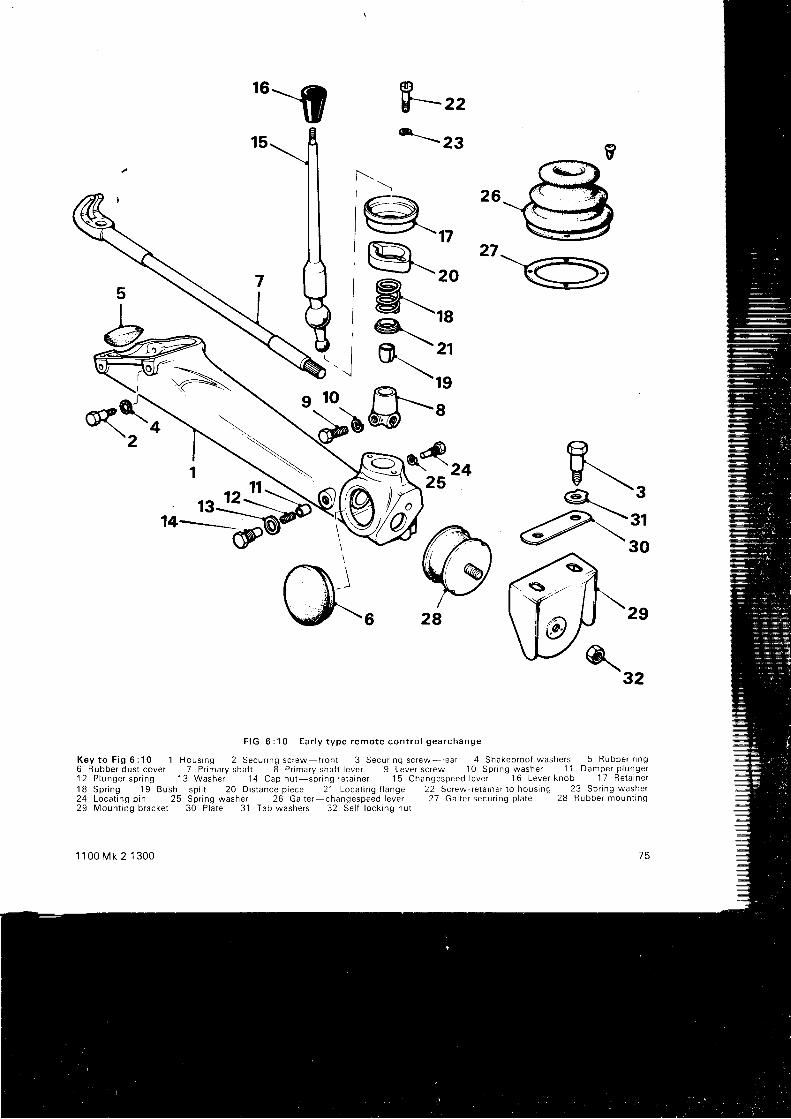
N
1@--'P-r,h,,ot-\zr
_$r
$--= r,*--zg
26
27
24
@\32
F I G 6 : 1 0 E a r l y t y p e r e m o t e c o n t r o l g e a r c h a n g e
K e y t o F i g 6 : 1 0 1 H o u s i n g 2 S e c u r i n g s c r e w { r o n t 3 S e c u r i n g s c r e w - r e a r 4 S h a k e p r o o f w a s h e r s 5 R u b b e r r i n g6 R u b b e r d u s t c o v e r 7 P r i m a r y s h a f t 8 P r i m a r y s h a f t l e v e r 9 L e v e r s c r e w 1 0 S p r i n g w a s h e r
' 1 1 D a m p e r p l u n g e r1 2 P l u n g e r s p r i n g 1 3 W a s h e r 1 4 C a p n u t s p r i n g r e t a r n e r 1 5 C h a n g e s p e e d l e v e r
' 1 6 L e v e r k n o b 1 7 R e t a i n e r1 8 S p r i n g 1 9 B u s h s p l i t 2 0 D i s t a n c e p i e c e 2 ' 1 L o c a l r n g l l a n g e 2 2 S c r e w r e l a i n e r t o h o u s i n g 2 3 S p r i n g w a s h e r2 4 L o c a t i n g p i n 2 5 S p r i n g w a s h e r 2 6 G a i t e r - c h a n g e s p e e d l e v e r 2 7 G a i t e r s e c u r i n g p l a t e 2 8 R u b b e r m o u n t t n g2 9 M o u n t i n g b r a c k e t 3 0 P l a t e 3 1 T a b w a s h e r s 3 2 S e l f l o c k i n g n u t
d\ 2 s
28
7 51 1 0 0 M k 2 1 3 0 0
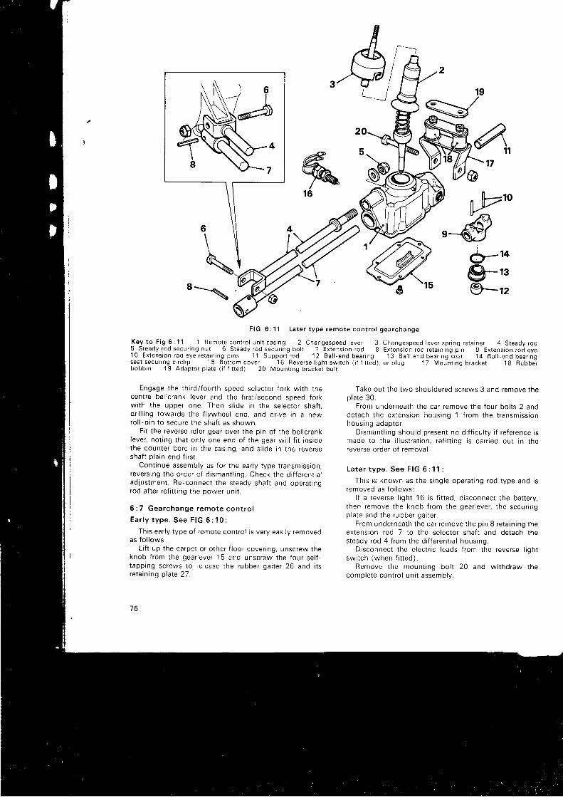
4,17
yfu'o€
d-to9-rs\/9-rz8 = \ ,
%16
F I G 5 : 1 1 L a t e r t y p e r e m o t e c o n t r o l g e a r c h a n g e
K e y t o F i g 6 : 1 1 1 R e m o t e c o n t r o l u n i t c a s i n g 2 C h a n g e s p e e d l e v e r 35 S t e a d y r o d s e c u r i n g n u t 6 S t e a d y r o d s e c u r i n g b o l t 7 E x t e n s i o n r o d 81 0 E x t e n s i o n r o d e y e r e t a i n i n g p i n s 1 1 S u p p o r t r o d 1 2 B a l l - e n d b e a r i n gseat secur ing c i rc l rp 15 Bot tom cover ' l
6 Reverse l igh l sw i tch ( i f f i t ted)bobb in ' l
9 Adaptor p la te ( i f f i t red) 20 Mounr ing bracker bo t r
Engage t he t h i r d / f ou r t h speed se lec to r t o r k w i t h t hecentre bel lcrank lever and the f i rs t /second speed forkw l t h t he uppe r one . Then s l i de i n t he se lec to r sha f t ,d r i l l i ng t owa rds t he f l ywhee l end , and d r i ve r n a newro l l - p i n t o secu re t he sha f t as shown .
F i t t he reve rse i d l e r gea r ove r t he p i n o f t he be l l c rankleve r , no t i ng t ha t on l y one end o f t he gea r w i l l f i t i n s i dethe coun te r bo re i n t he cas ing , and s i i de i n t he reve rseshaft p la in end f i rs t .
Cont inue assembly as for the ear ly type t ransmission,reve rs i ng t he o rde r o f d i sman t l i ng . Check t he d i f f e ren t i a lad jus tmen t . Re -connec t t he s teady sha f t and ope ra t i ngrod a f t e r r e f i t t i ng t he power un t t .
6 : 7 Gea rchange remo te con t ro l
E a r l y t y p e . S e e F I G 6 : 1 0 :
This ear ly type of remote contro l is very easi ly removedas f o l l ows :
L i f t up t he ca rpe t o r o the r f l oo r cove r i ng , unsc rew theknob f r om the gea r l eve r 15 and unsc rew the f ou r se l f -t app ing sc rews t o r e l ease t he rubbe r ga i t e r 26 and i t sreta in ing plate 21.
7 6
d,X_t
Changespeed lever spr ing re ta iner 4 S teady rodExtens ion rod re ta in ing p in 9 Ex lens ion rod eye
1 3 B a l l e n d b e a r i n g s e a l 1 4 B a l l - e n d b e a r i n go r p l u g 1 7 M o u n t i n g b r a c k e t 1 8 R u b b e r
Take out the two shouldered screws 3 and remove thep la te 30 .
F rom unde rnea th t he ca r r emove t he f ou r bo l t s 2 andde tach t he ex tens ion housng 1 f r om the t r ansm iss i onhous ing adap to r .
D i sman t l i ng shou ld p resen t no d i f f i cu l t y i f r e f e rence i smade t o t he i l l u s t r a t i on , r e f i t t i ng i s ca r r i ed ou t i n t hereverse order of removal .
La te r t ype . See F IG 6 : 1 1 :
Th i s r s known as t he s i ng le ope ra t i ng rod t ype and i sremoved as f o l l ows :
l f a reverse l ight ' l 6 is f i t ted, d isconnect the bat tery,
t hen remove t he knob f r om the gea r l eve r , t he secu r i ngp la te and t he rubbe r ga i t e r .
F rom unde rnea th t he ca r r emove t he p i n 8 r e ta i n i ng t heextension rod 7 to the selector shaf t and detach thesteady rod 4 f rom the di f ferent ia l housing.
Disconnect the electr ic leads f rom the reverse l ightsw i t ch (when f i t t ed ) .
Remove t he moun t i ng bo l t 20 and w i t hd raw thecomp le te con t ro l un i t assemb ly .
Twist the spr ing reta iner 3 to re lease the gear lever 2.Remove the steady rod and reverse l ight swi tch.D r i ve ou t t he two p i ns 10 and w i t hd raw the ex tens ion
rod 7, end plug, support rod 1 1 and the eye 9.Remove t he c i r c l i p 14 and d i sman t l e t he ba l l - end
bea r i ng sea t 13 and bea r i ng 12 .Reassembly and f i t t ing are carr ied out in the reverse
order to the above, but note the fo l lowing points.A lways use new re ta i n i ng p i ns 10 and 8 .Note that the bot tom cover 15 is f i t ted wi th the reverse
stop on the s ide opposi te to the reverse swi tch or i tsp l ug . '
l f the spr ing reta iner has been pul l ing over i ts reta in ingpins, longer p ins may be f i t ted and secured wi th Loct i te.
Leave the t ightening of the mount ing bol t 20 unt i l theend of the operat ion.
Reve rse l i gh t sw i t ch :
On the ear ly remote contro l uni ts the reverse l ightswi tch is screwed into the f ront of the t ransmissioncasing in p lace of the reverse check plunger, spr ing andplug. No adjustment is possib le wi th thrs type.
On later gearshi f t uni ts the reverse lamp switch may beadiusted i f necessary as fo l lows:
Engage reverse gear. d isconnect the leads f rom thesw i t ch and l oosen t he l ock i ng nu t .
Connect a test lamp and bat tery across the swi tchterminals and then unscrew the swi tch body unt i l thetest lamp goes out .
Screw in the swi tch unt l l the lamp just l ights and then afur ther hal f turn and secure wi th the locknut.
1 1 0 0 M k 2 1 3 0 0
Remove the test lamp and battery, reconnect the leadsand check for correct operation.
6 : 8 F a u l t d i a g n o s i s(a) Jumping ou t o f gear
1 Broken spring behind selector rod locatinq plunger2 Excessively worn groove in selector rod3 Worn synchromesh coupling dogs4 Fork to selector rod securing screw loose
(b) No isy t ransmiss ion
1 Insu f f i c ien t o i l2 Excessive end f loat of laygear3 Incorrect end f loat of idler gear4 Incorrect preload on dif ferential bearings5 Worn or damaged bearings6 Worn bushes on third molion shaft7 Worn or damaged gear teeth
(c ) D i f f i cu l ty in engag ing gear
1 Incorrect clutch pedal adjustment2 Worn synchromesh cones3 First and second gear incorrectly assembled on hub
(d) O i l leaks
1 Damaged joint washers2 Worn or damaged oi l seals3 Faulty joint faces on covers4 Ineffect ive oi l seal on gearchange operating shaft
77
CHAPTER 7
AUTOMATIC TRANSMISS ION
7 : 1 Desc r i p t i on7 : 2 P o w e r f l o w ( m e c h a n i c a l )7 : 3 F a u l t d i a g n o s i s7 : 4 Road t es t i ng7 : 5 Ad jus tmen ts
7 : 1 Desc r i p t i on
The automat ic t ransmission uses a three element f lu idtorque converter in the place of a convent ional f lywheeland c lutch, coupled through an id ler gear to a bevel geartra in assembly which provides four foruvard speeds andreve rse . The l ayou t o f t he sys tem i s shown i n F IG 7 :1wh i ch a l so i l l u s t r a tes t he
' c i r cu l a t i on ' o f t he ope ra t i ng
f l u i d t o t h e v a r i o u s c o m p o n e n t s . I n F I G S 7 : 2 1 o 7 : 7 t n ed iag rams i nd i ca te how the va r i ous ra t i os a re ob ta i ned bvthe engagement of the appropr iate f r ic t ion members.
The f inal dr ive is t ransmit ted to a convent ionald i f f e ren t i a l un i t , and so t he t he road whee l s t h rough t hedr ive shaf ts and their constant veloci ty jo ints.
The comp le te gea r t r a i n assemb ly , i nc l ud ing t hed i f f e ren t i a l , i s housed be low and pa ra l l e l t o t he eng tnec ranksha f t i n a cas ing wh i ch a l so se rves as t he eng inesumo .
Gear select ion is by means of a f loor mounted sevenposi t ion gated quadrant . The reverse. neutra l and dr iveposi t ions are for normal automat ic dr iv ing, wi th the f i rs t ,second , t h i r d and f ou r t h pos i t i ons used f o r manua lope ra t i on o r ove r - r i de as r equ r red . Th i s a r rangemen tal lows the system to be used as a fu l ly automat lc fourspeed t ransmissron f rom rest to maximum speed wi th the
1 1 0 0 M k 2 1 3 0 0
7 : 6 R e m o v i n g t h e t r a n s m i s s i o n u n i t7 :7 Se rv i c i ng t he d i f f e ren t i a l assemb ly7 : 8 Se rv i c i ng t he gea rchange cab le7 :9 l d l e r gea r l ub r i ca t i on rese rvo i r
gea rs chang ing au toma t t ca l l y acco rd i ng t o t h ro t t l epos i t i on and l oad . l f i t i s des i r ed t o se l ec t a l owe r gea r f o rg rea te r acce le ra t i on , t he acce le ra to r peda l i s ' k i c keddown ' t o f u l l t h ro t t l e pos i t i on and t h i s immed ia te l yp roduces t he change .
Manual contro l of the selector lever provides raprdchanges o f a l l f ou r f o rwa rd gea rs , bu t i t i s impo r tan t t ha tdownward changes be made at the correct road speeds orse r i ous damage t o t he au toma t i c t r ansm iss i on un t t mayres u t t .
Second , t h i r d and f ou r t h gea rs p rov i de eng ine b rak i ngin bo th au toma t i c d r i ve and manua l , wh i l e i n f i r s t gea rt he re i s f r eewhee l i ng du r i ng dece le ra t i on . Manua lse lec t i on o f t h i r d o r second gea r g i ves eng ine b rak i ng andalso al lows the retent ion of a lower gear to sui t roadcond r t i ons o r f o r t he descen t o f s t eep h t l l s .
T h e m a i n h i g h - o u t p u t o i l p u m p 2 i n F I G 7 : 1 p r o v i d e so i l unde r p ressu re bo th f o r eng ine l ub r i ca t i on and f o r t heau toma t i c t r ansm iss i on . The va l ve b l ock assemb ly 4directs the oi l f low to the converter by way of p ipe 6, theeng ine by p i pe 5 and by p i pes 13 t o t he se rvos ope ra t i ngthe selector brake bands.
The two hyd rau l i ca l l y ope ra ted c l u t ches 1 0 and 12 a reengaged for top and reverse gear work or for a l l forwardmot ion of the car respect ively.
7 9

-\
\
F I G 7 : 1 T h e c o m p o n e n t s o f t h e a u t o m a t i c t r a n s m i s s i o n , s h o w i n g f l u i d c i r c u l a t i o n i n d i c a t e d b y a r r o w s
K e y t o F i g T : 1 1 M a i n o i l s t r a i n e r 2 O i l p u m p 3 O r l f i l t e r a s s e m b l y 4 V a l v e b l o c k 5 E n g i n e o i l f e e d 6 C o n v e r t e rf e e d p i p e 7 c o n v e r t e r t o l o w p r e s s u r e v a l v e f e e d 8 L o w p r e s s u r e v a l v e 9 G e a r t r a i n " 1 0
T o p a n d r e v e r s e c t u t c h1 1 G o v e r n o r 1 2 F o r w a r d c l u t c h 1 3 S e r v o u n i t 1 4 A u x i l i a r y p u m p o i l s t r a i n e r 1 5 A u x i l i a r y p u m p
.t.o\
A gove rno r , o f t he sp r i ng - l oaded bob -we igh t t ype , i sused to delay gear shrf ts as the accelerator pedal isdepressed. The low pressure valve 8 prevents the converterd ra i n i ng when s topped and so be rng no i sy and i ne f f i c i en twhen restar t ing.
The aux i l i a r y pump 15 i s r espons i ve t o r oad speed on l yand i s used when t ow-s ta r t i ng , bu t i t mus t be no ted t ha rt h i s i s no t poss ib l e when an engagemen t con t ro l un t t r sf i t t ed as on l a t e r t r ansm iss i ons .
The engagemen t con t ro l un i t i s assemb led i n t o t het ransm iss i on i n o rde r t o e l im ina te excess i ve movemen tof the car when select ing a forward dr ive range f rom theres l pos r t on .
BO
7 : 2 P o w e r f l o w ( m e c h a n i c a l )The power f l ow d i ag rams g i ven i n F IGS 7 : 2 , 3 , 4 , i ,
6 and 7 indicate how the four forward speeds and reversea re ob ta i ned by t he ope ra t i on o f t he va r i ous c l u t ches andf r i c t i on bands .
The c ranksha f t 1 d r i ves t he ou te r cas i ng o f t heconve r t e r wh i ch i n t u rn , by t he ac t i on o f t he o i l w i t hwh i ch i t i s f i l l ed . d r i ves an i nne r member wh i ch i s con -nec ted d i r ec t l y t o t he ou tpu t gea r 2 .
Be low t he ou tpu t gea r w i l l be seen t he i d l e r gea r 3th rough wh i ch t he d r i ve i s passed t o t he i npL t t gea r o f t het ransmrss ion assemb ly .
I n v i ew o f t he spec ia l equ ipmen t needed f o r mos t
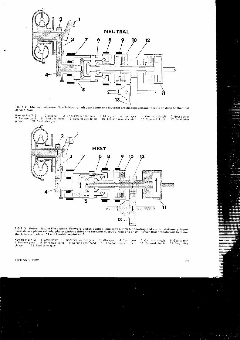
F I G 7 : 2 M e c h a n i c a l p o w e r f l o w i n N e u t r a l A l l g e a r b a n d s a n d c l u t c h e s a r e d i s e n g a g e d a n d t h e r e i s n o d r i v e t o t h e f i n a ld r i v e p i n i o n
K e y t o F i g 7 : 2 1 C r a n k s h a f t 27 F e v e r s e b a n d 8 T h i r d g e a r b a n dp i n i o n 1 3 F i n a l d r i v e g e a r
c o r v e r t e r o u t p u t g e a r 3 l d i e r g e a r 4 I n p u l g e a r 5 o n e w a y c l u t c h 6 G e a r c a r r i e r9 S e c o n d g e a r b a n d 1 0 T o p a n d r e v e r s e c l u t c h 1 1 F o r w a r d c l u t c h 1 2 F i n a l o r r v e
F I G 7 : 3 P o w e r f l o w i n F i r s t s p e e d . F o r w a r d c l u t c h a p p l i e d , o n e - w a y c l u t c h 5 o p e r a t i n g a n d c a r r i e r s t a t i o n a r y . I n p u tb e v e l d r i v e s p l a n e t w h e e l s , p l a n e t p i n i o n s d r i v e t h e f o r w a r d o u t p u t p i n i o n a n d s h a f t . P o - w e r t h u s t r a n s { e r r e d t o m a i n -s h a f t , f o r w a r d c l u t c h 1 1 a n d f i n a l d r i v e o i n i o n 1 2
K e y t o F i g 7 : 3 1 C r a n k s h a { t 2 C o n v e r t e r o u t p u t g e a r 3 l d l e r g e a r 4 i n p u t g e a r 57 R e v e r s e b a n d 8 T h i r d g e a r b a n d 9 S e c o n d g e a r b a n d 1 0 T o p a n d r e v e r s e c l u i c h 1 lp r n r o n ' 1
3 F i n a l d n v e g e a r
1 1 0 0 M k 2 1 3 0 0
O n e w a y c l u l c h 6 G e a r c a r r i e rF o r w a r d c l u t c h 1 2 F i n a l d r i v e
8 1
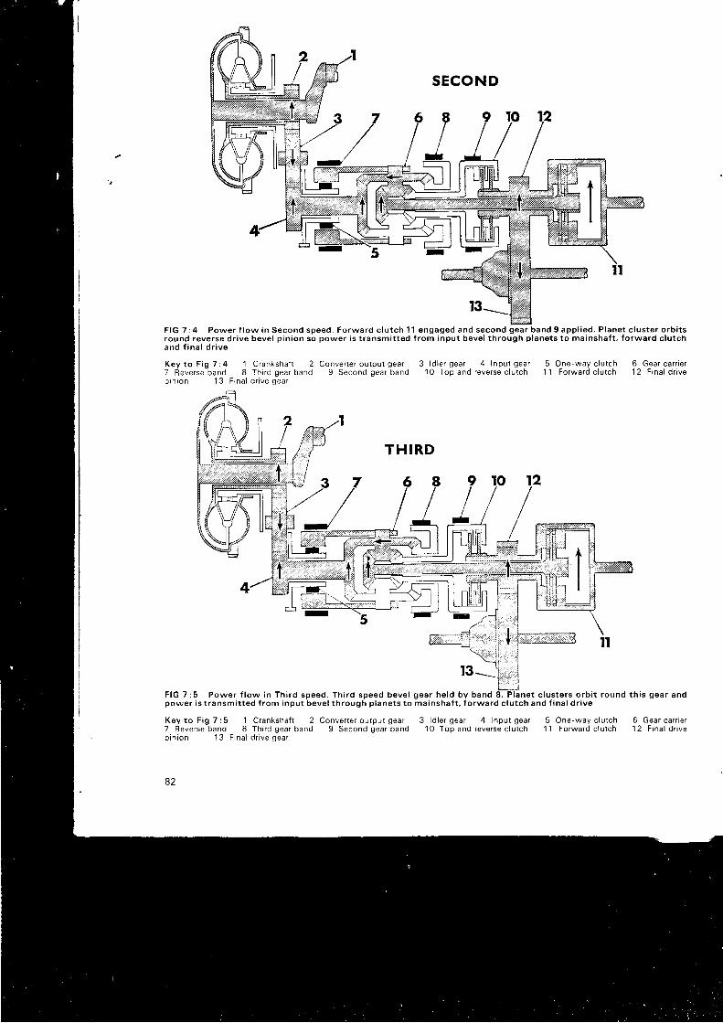
F l G T : 4 P o w e r f l o w i n S e c o n d s p e e d . F o r w a r d c l u t c h l l e n g a g e d a n d s e c o n d g e a r b a n d 9 a p p l i e d . P l a n e t c l u s t e r o r b i t sround reverse dr ive beve l p in ion so power i s t ransmi t ted f rom input beve l th rough p lanets to ma inshaf t , fo rward c lu tcha n d f i n a l d r i v e
K e y t o F i g 7 : 4 1 C r a n k s h a f l 27 Reverse band 8 Th i rd gear bandp r n r o n 1 3 F i n a l d r i v e g e a r
C o n v e r t e r o u t p u t g e a r 3 l d l e r g e a r 4 I n p u l g e a r 5 O n e - w a y c l u t c h 6 G e a r c a r r i e r9 S e c o n d g e a r b a n d 1 0 T o p a n d r e v e r s e c l u t c h 1 1 F o r w a r d c l u t c h 1 2 F i n a l d r i v e
T H I R D
F I G 7 : 5 P o w e r f l o w i n T h i r d s p e e d . T h i r d s p e e d b e v e l g e a r h e l d b y b a n d 8 . P l a n e t c l u s t e r s o r b i t r o u n d t h i s g e a r a n dp o w e r i s t r a n s m i t t e d f r o m i n p u t b e v e l t h r o u g h p l a n e t s t o m a i n s h a f t , f o r w a r d c l u t c h a n d f i n a l d r i v e
K e y . t o F i g 7 : 5 1 C r a n k s h a f t 27 Reverse band 8 Th i rd gear bandp i n i o n 1 3 F i n a l d r i v e g e a r
82
Conver te r ou tpu t gear9 Second gear band
3 l d l e r g e a r 4 l n p u t g e a r10 Top and reverse c lu tch
One-way c lu tch 6 Gear car r ie rForward c lu tch 12 F ina l d r ive
51 1
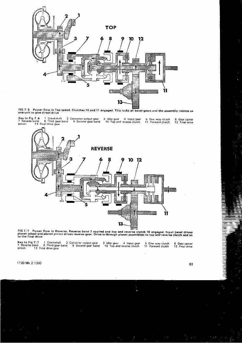
TOP
c lu tches 10 and 11 engaged. Th is locks a l l beve l gears and the assembly ro ta tes as
Conver te r ou tpu t gear 3 ld le r gear 4 Input gear9 Second gear band 10 Top and reverse c lu tch
One-way c lu tch 6 Gear car r ie rForward c lu tch 12 F ina l d r ive
8
J
F I G 7 : 6 P o w e r f l o w i n T o p s p e e done un i t to g ive d i rec t d r iv€
K e y t o F i g 7 : 6 1 C r a n k s h a t l 27 Reverse band 8 Th i rd gear bandp i n i o n 1 3 F i n a l d r i v e g e a r
5
FIG 7:7 Power f low in Re.verse. Reverse band 7 appl ied and top and reverse c lutch 10 engaged. lnput bev€l dr iv6splanet wheel and planet p in ion dr ives reverse geur. Ei i ive is throujh f t inet assemul ies to top;n; revei iet rutcn ana soto the f inal dr ive
Key to Fig 7:7 1 Crankshaft . 2 Convel ter output gear 3 ld ler gear 4 Input gear 5 One-way c lutch 6 Gear carr ier7. Reverse bq1d - 8 Third gear band g Second lear-band 10 To6 jnd revers; ; iJrch 1l Forward ctutch 12 Final dr ivepin ion 13 Final dr ive gear
1 1 0 0 M k 2 1 3 0 0 83
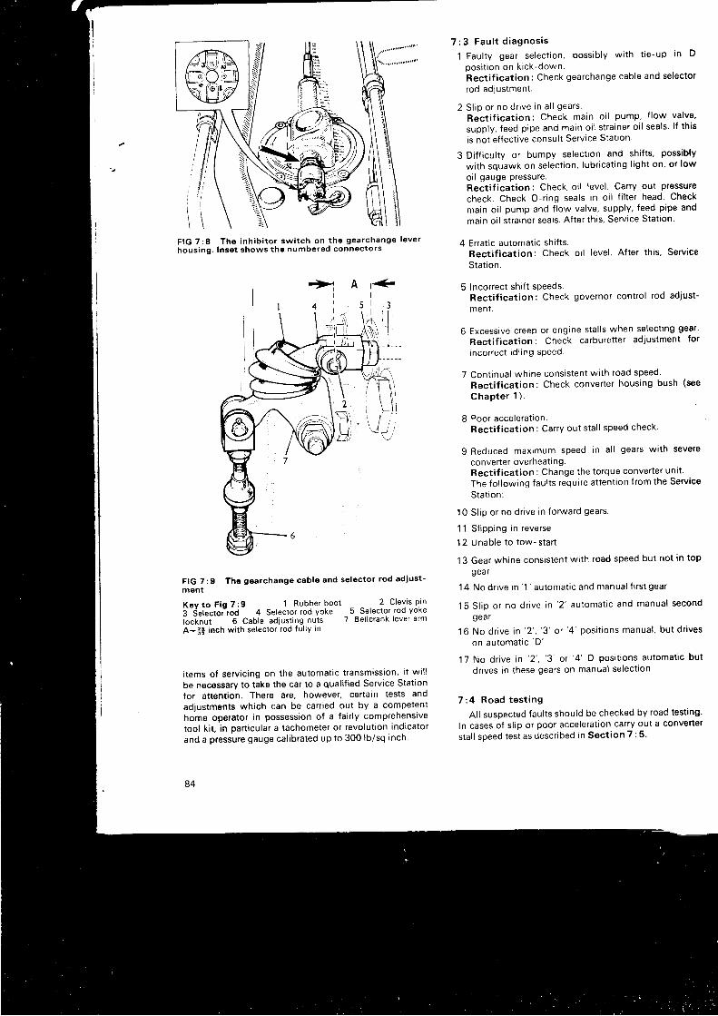
F I G 7 : 8 T h o i n h i b i t o r s w i t c h o n t h e g e a r c h a n g e l e v e r
hous ing . Inse t shows tho numbered conn€ctors
r>1I
1 "
FIG 7 :9 The gearchange cab le and se lec tor rod ad jus t -
ment
7 : 3 F a u l t d i a g n o s i s
l Faul ty gear select ion. possib ly wi th t ie-up in D
pos i t i on on k i ck -down .Rect i f icat ion: Check gearchange cable and selector
rod adlustment.
2 S l i p o r no d r i ve i n a l l gea rs .
Rec t i f i ca t i on : Check ma in o i l pump , f l ow va l ve '
supply, feed pipe and main oi l s t ra iner o i l seals l f th is
is not ef fect ive consul t Serv ice Stat ion
3 Di f f icul ty or bumpy select ion and shi f ts , possib ly
wi th squawk on select ion, lubr icat ing l ight on, or low
oi l gauge pressure.Rect i f icat ion: Check oi l level Carry out pressure
check. Check O-r ing seals in o i l f i l ter head Check
main oi l pump and f low valve, supply, feed pipe and
main oi l s t ra iner seals. Af ter th is, Service Stat ion
4 Errat ic automat ic shi f ts .Rect i f icat ion: Check oi l level . Af ter th is, Service
Stat ion.
5 Incorrect shi f t sPeeds.Rect i f icat ion: Check governor contro l rod ad. iust-
men t .
6 Excessive creep or engine sta l ls when select ing gear '
Rect i f icat ion: Check carburet ter adjustment fot
incorrect id l ing sPeed
7 Cont inual whine consistent wi th road speed'
Rect i f icat ion: Check converter housing bush (see
Chap te r 1 ) .
8 Poor accelerat ion.Rect i f icat ion: Carry out sta l l speed check'
9 Reduced maximum speed in a l l gears wi th severe
converter overheat l ng.Rect i f icat ion: Change the torque converter unl t '
The fo l lowing faul ts require at tent ion f rom the Service
Stat ion:
10 Sl ip or no dr ive in forward gears.
11 S l i pp i ng i n r eve rse
12 Unable to tow- star t
13 Gear whine consistent wi th road speed but not in top
gea r
14 No d r i ve i n ' 1 ' au toma t i c
and manua l f i r s t gea r
15 S l i p o r no d r i ve i n ' 2 ' au toma t i c and manua l second
gea r
1 6 No d r i ve i n ' 2 ' , ' 3 '
o r ' 4 ' pos i t i ons manua l , bu t d r i ves
on automat ic 'D'
17 No dr ive in '2 ' , '3 '
or '4 '
D posi t ions automat ic but
dr ives in these gears on manual select ion
7 :4 Road t es t i ng
Al l susoected faul ts should be checked by road test ing '
In cases of s l ip or poor accelerat ion carry out a convener
stal l speed test as descr ibed in Sect ion 7 :5 '
A
a
\1\
i l l ll u
ic
K e y t o F i g 7 : 9 1 R u b b e r b o o t3 Se lec lo r rod 4 Se lec tor rod Yokelocknut 6 Cab le ad jus t ing nu tsA:3* inch w i th se lec tor rod fu l lY in
2 C lev is P in5 Se lec tor rod Yoke
7 Be l lc rank lever a rm
i tems of servicing on the automatic transmission, i t wi l lbe necessary to take the car to a qual i f ied Service Stationfor attention. There are, however, certain tests andadjustments which can be canied out by a competenthome operator in possession of a fair ly comprehenslvetool ki t , in part icular a tachometer or revolut ion indicatorand a pressure gauge cal ibrated up to 300 lbi sq inch
84
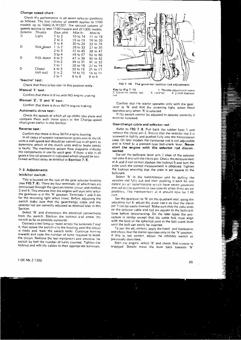
Change speed cha r t :
Check the performance in a l l seven selector posi t ionsas f o l l ows . The f i r s t co l umn o f speeds app l i es t o 1100mode l s up t o 1OAG/A /H12O7 . The second co lumn o fspeeds app l i es t o l a t e r 1100 mode l s and a l l 1300 mode l s .Selector Throttle Gear shift Mitelhr Mile/hrD L i gh t 1 t o 2
z t o 33 t o 4
D Kickjown 1 to 22 t o 33 t o 4
D K ick-down 4 to 33 t o 22 t o 1
D Closed 4 to 3( ro l l ou t ) 3 to 2
2 r o 1' Neu t ra l '
t es t :
Check that there is key star t in th is posi t ion onlv.
M a n u a l ' 1 ' t e s t :
Con f i rm t ha t t he re i s d r i ve w i t h NO eng ine b rak i ng .
Manua f ' 2 ' , ' 3 ' and ' 4 ' t es r :
Con f i rm t ha t t he re i s d r i ve WITH eng ine b rak rng .
Au toma t i c d r i ve t es t :
Check t he speeds a t wh i ch a l l up - sh i f t s t ake p l ace andcompare t hem w i t h t hose g i ven l n t he Change -speedcha r t g i ven ea r l i e r i n t h i s Sec t i on .
Reverse test :
Con f i rm t ha t t he re i s d r i ve WITH eng ine b rak i ng .In a l l cases of suspect t ransmission gears and/or c lutch
uni ts a sta l l speed test should be carr ied out in a l l qears rode te rm ine wh i ch o f t he c l u t ch un i t s and /o r b rakJ bandsis faul ty. The mechanical power f low diagrams indicatethe components in use for each gear. l f there is s l ip in a l lgears a low oi l pressure is indicated which should be con,f i fmed wi thout delay as detai led in Sect ion 7 :5.
7 :5 Ad jus tmen ts
Inh ib i t o r sw i t ch :
This is located on the rear of the gear selector housing(see FIG 7 :8) . There are four terminals, of which two areconnected through the igni t ion/star ter c i rcui t and marreo2 and 4. This ensures that the engine wi l l s tar t only whenthe gea r l eve r i s i n t he 'N 'pos i t i on . Te rm ina l s 1 and 3 a refor the revers ing l ight when f i t ted. Before adjust ing theswitch make sure that the gearchange cable and theselector rod are correct ly adjusted as detai led later in th lsSect ion.
Se lec t 'N '
and d i sconnec t t he e l ec t r i ca l connec t i onsfrom the swi tch. Slacken the locknut and screw theswitch as far as possib le outwards.
Connect a test lamp or meter across the terminals 2 and4 , t hen sc rew the sw i t ch i n t o t he hous ing un t i l t he c i r cu i ti s made and mark t he sw i t ch body . Con t i nue t u rn i nganwards and note the number of turns required to breakthe c i fcui t . Remove the test equipment and unscrew theswitch by hal f the number of turns counted. Tighten thelocknut and ref i t the cables to their appropr iate terminals.
1 1 p 0 M k 2 1 3 0 0
1 0 t o 1 4 1 1 t o 1 51 5 t o 1 9 1 6 t o 2 020 to 24 22 to 2625 to 33 27 to 3537 to 45 39 to 4749 to 57 52 to 604 7 t o 3 9 5 0 : ! 4 239 to 31 41 to 332 6 t o 1 8 2 1 t o i 92 0 t o 1 6 2 1 t o 1 71 4 t o ' 1 0 1 5 t o 1 18 t o 4 9 t o 5
F I G 7 : 1 0 T h e g o v e r n o r c o n t r o l r o d a d j u s t m e n t
K e y t o F i g 7 : 1 02 Governor contro l rodrod
' I Thro t t le ad jus tmen l sc rew
3 L o c k n u t 4 + i n c h d i a m e t e r
Conf i rm that the star ter operates only wi th the gear_lever at
'N ' and that the revers ing l ight , when f i t ted
ope ra tes on l y when 'R '
i s se l ec ted .l f the swi tch cannot be adjusted to operate correctrV r l
must be renewed.
Gea rchange cab le and se lec to r r od :
Re fe r t o F IG 7 :9 . Pu l l back t he rubbe r boo t 1 anc iremove the c levis p in 2. Ensure that the selector rod 3 issc rewed i n t i gh t l y and pushed f u l l y i n t o t he t r ansm iss i oncase. On later models the t ransverse rod is not adiustableand is f i t ted to a pressed-type bel l -crank lever. Neverstar t the engine wi th the selector rod discon-nected.
Swivel the bel lcrank lever arm 7 c lear of the selecrorrod yoke 4 and ref i t the c levis p in. Check the measuremenlat A and i f not correct s lacken the locknut b and turn theyoke unt i l the correct measurement is obtained. Tightenthe locknut ensur ing tnat the yoke is set square to thebe l I c rank
S e l e c t ' N ' i n t h e t r a n s m i s s i o n u n i t b y p u l l i n g t h ese lec to r r od f u l l y ou t and t hen push ing i t back by onede ten t on a l l t r ansm iss i ons wh i ch have seven pos l t i onsmarked on t he quad ran t o r two de ten t s when t he re a re s i xpos r t r ons . The measu remen t a t A shou ld now be 1 .45r n c h .
Se t t he gea r l eve r t o 'N '
on t he quad ran t and , us Ing t headlust ing nut 6, adjust the outer cable so that the c levisp i n 2 can be eas i l y i nse r t ed . Make su re t ha t t he yoke endson the selector cable and rod are square to the bel lcranKlever before reconnect ing. On the later types the pro_cedure is s imi lar except that the cable fork must a l rgnwith the bore of the spher ical jo int in the bel l -crank leverunt i l the bol t can easi ly be inserted.
To test the adjustment, apply the hand- and footbrakesand check that the star ter operates only in the
'N' posi t ion.l f t h i s i s no t co r rec t , ad j us t t he i nh i b i t o r sw i t ch aspreviously descr ibed.
Star t the engine, select 'R '
and check that reverse isengaged. Slowly move the lever back towards .N,
85

F IG 7 :11 Check ing t he p ressu res and t he s ta l l speedw i t h se r v i ce t oo l 18G.677 .2 and adap to r 18G.677 .C(a r rowed )
check ing t ha t t he gea r i s d i sengaged j us t be fo re o r assoon as t he l eve r d rops i n t o t he
'N ' pos i t i on on t he quad -ran t . Repea t t h i s p rocedu re i n t he f i r s t gea r ' 1 ' pos i t i on .
Re -ad jus t t he ou te r cab le s l i gh t l y i f necessa ry t o ob ta i nthe above cond i t i ons .
Ensu re t ha t a l l nu t s a re t i gh t and t he c l ev i s p i nssecu red . Pack t he rubbe r boo t s w i t h Lammo l g rease andre f i t . F i t t he wea the r sh i e l d i f app l i cab le . Ca r r y ou t a r oadtes t , check ing t he ope ra t i on i n each gea r l eve r pos i t i on .
Gove rno r con t ro l r od ad jus tmen t :
Run t he eng ine up t o no rma l wo rk i ng t empe ra tu re andd i sconnec t t he gove rno r con t ro l r od a t t he ca rbu re t t e r( see F IG 7 :10 ) . W i t h t he ca rbu re t t e r co r rec t l y t unedadjust the throt t le screw 1 to g ive a tachometer reading of650 rev /m in a t t i c kove r .
I nse r t a j i n ch d i ame te r r od 4 t h rough t he ho le i n t hegove rno r con t ro l r od be l l c rank l eve r and i n t o t he ho lei n t he t r ansm iss i on case . S lacken t he l ocknu t 3 and ad jus tt he l eng th o f t he rod t o su i t t he ca rbu re t t e r l i n kage i n t het i c k -ove r pos i t i on .
Reconnect the contro l rod to the carburet ter . T ightenthe ba l l j o i n t l o cknu t and remove t he check ing rod .
S ta l l speed check :
Run t he eng ine up t o no rma l wo rk i ng t empe ra tu re andcheck t he o i l l e ve l . Connec t a su i t ab le t achome te r . App l ythe f oo t and hand b rakes , se l ec t any gea r pos i t i on
F IG 7 : 12 Remov ing t he d i f f e ren t i a l assemb ly
excep t 'N ' o r ' 1 ' , g i ve max imum th ro t t l e f o r no t mo re t hanten seconds and no te t he t achome te r r ead ing . comparethe f i gu re ob ta i ned w i t h t he t ab le be low :
P ressu re check :
Check and t op up t he o i l l e ve l . Remove t he p ressu repo in t p l ug on t he eng ine o i l f i l t e r and connec t a p ressu regauge read ing t o 2BO l b / sq i nch . F IG 7 : 11 showsse rv i ce t oo l 18G.611 .Zand adap to r 18G.677 .C i n use .
Run t he eng ine un t i l t he o i l t empe ra tu re i s 80oC o r176oF . t hen run i t a t ' 1 000 rev /m in and check t he f o l l owi ng app rox rma te p ressu res :
1 I n a l l gea r pos i t i ons excep t 'R ' a p ressu re o f 95 t o 105lb i sq i nch .
2 I n pos i t i on 'R ' t he p ressu re shou ld be be tween 143
and 1 57 l b / sq i nch excep t when t he engagemen tcon t ro l dev i ce i s f i t t ed when 162 t o 118 l b / sq i nchshou ld be reg i s t e red .l f t hese app rox ima te p ressu res a re no t ob ta i nab le see
S e c t i o n 7 : 3 .
7 : 6 Remov ing t he t r ansm iss i on un i t :
The eng ine and t r ansm iss i on assemb ly i s r emovedf rom the ca r as i ns t r uc ted i n Chap te r 1 , bu t t he t r ans -m iss i on shou ld be sepa ra ted f r om the eng ine on l y i f i t i snecessa ry t o f i t a r ep lacemen t eng ine , t r ansm iss i on cas ingo r t o r emove t he ma in o i l s t r a i ne r p i ckup p i pe and sea l s .
Rectif ication
Change t o rque conve r t e rCheck t r ansm iss ron un i t ( see f i na l no te i n Sec t i on
7 : 4 )Check eng ine
Model1 098 cc1275cc
Both
Rev lmin1 600 to 1 7001 700 to 1 800Under 1 000Over 1 900
Under 1 600
ConditionSat isfactorySat isfactoryS ta to r f r eewhee l s l i pT ransm iss i on s l i p
Eng ine down f o r power
86
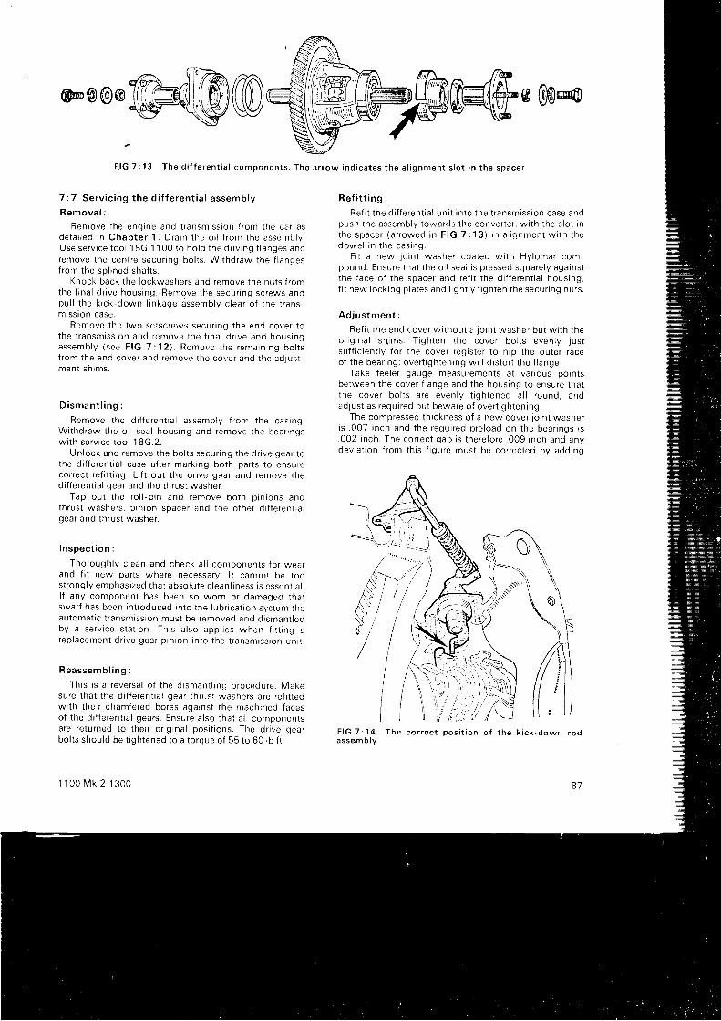
7 :7 Se rv i c i ng t he d i f f e ren t i a l assemb ly
R e m o v a l :
Remove t he eng ine and t r ansm iss i on f r om the ca r asde ta i l ed i n Chap te r 1 . D ra i n t he o i l f r om the assemb ly .Use se rv i ce t oo l 18G.1 100 t o ho ld t he d r i v i ng f l anges andremove t he cen t re secu r i ng bo l t s . W i t hd raw the f l angesfro:n the sol ined shaf ts.
Knock back the lockwashers and remove the nuts f romthe f i na l d r i ve hous ing . Remove t he secu r i ng sc rews andpu l l t he k i ck -down l i nkage dssemb ly c i ea r o f t he t r ansmrss ton case .
Remove the two setscrews secur ing the end cover tot he t r ansm iss i on and remove t he f i na l d r i ve and hous ingassemb ly ( see F IG 7 :12 ) . Remove t he rema in i ng bo l t sf r om the end cove r and remove t he cove r and t he ad ius tmen t sn lms .
D i s m a n t l i n g :
Remove t he d i f f e ren t i a l assemb ly f r om the cas ing .W i thd raw the o i l sea l hous ing and remove t he bea r i ngsw i t h se r v i ce t oo l 18G.2 .
Un lock and remove t he bo l t s secu r i ng t he d r i ve gea r t othe di f ferent ia l case af ter marking both parts to ensurecorrect ref i t t ing. L i f t out the dr ive gear and remove thed i f f e ren t i a l gea r and t he t h rus t washe r
Tap ou t t he ro l l - p i n and remove bo th p i n i ons andth rus t washe rs , p i n i on space r and t he o the r d i i f e ren t i a lgear and thrust washer.
I nspec t i on :
Tho rough l y c l ean and check a l l componen ts f o r wea rand f i t new parts where necessary. l t cannot be toos t rong l y emphas i zed t ha t abso lu te c l ean l i ness i s essen I | a r .l f any componen t has been so wo rn o r damaged t ha tswa r f has been i n t r oduced i n t o t he l ub r i ca t i on sys tem theau toma t i c t r ansm iss i on mus t be removed and d i sman t reoby a se rv i ce s ta t i on . Th i s a l so app l i es when f r t t i ng arep lacemen t d r i ve gea r p i n i on i n t o t he t r ansm iss i on un i t .
R e a s s e m b l i n g :
Th i s i s a r eve rsa l o f t he d i sman t l i ng p rocedu re . Makesure that the di f ferent ia l gear thrust washers are ref i t tedw i t h t he i r chamfe red bo res aga ins t t he mach ined f aceso f t he d i f f e ren t i a l gea rs . Ensu re a l so t ha t a l l componen tsa re r e tu rned t o t he i r o r i g i na l pos r t i ons . The d r i ve gea rbo l t s shou ld be t i gh tened t o a t o rque o f 55 t o 60 l b f t .
1 1 0 0 M k 2 1 3 0 0
@ @ @
R e f i t t i n g :
Re f i t t he d i f f e ren t i a l un i t i n t o t he t r ansm iss ron case andpush t he assemb lv t owa rds t he conve r t e r , w i t h t he s l o t i nt h e s p a c e r ( a r r o w e d i n F I G 7 : 1 3 ) i n a l i g n m e n t w i t h t h edowe l i n t he cas ing .
F i t a new j o i n t washe r coa ted w i t h Hy lomar com-pound . Ensu re t ha t t he o i l sea l i s p ressed squa re l y aga ins tt he f ace o f t he space r and re f i t t he d i f { e ren t i a l hous ing ,f i t new l ock i ng p l a tes and l i gh t l y t i gh ten t he secu r i ng nu t s .
Ad jus tmen t :
Re f i t t he end cove r w i t hou t a j o i n t washe r bu t w i t h t heo r i g i na l sh ims . T i gh ten t he cove r bo l t s even l y j us tsu f f i c i en t l y f o r t he cove r r eg i s t e r t o n i p t he ou te r r aceo f t he bea r i ng ; ove r t i gh ten ing w r l l d i s t o r t t he f l ange .
Take f ee le r gauge measu remen ts a t va r i ous po in t sbe tween t he cove r f l ange and t he hous ing t o ensu re t ha tt he cove r bo l t s a re even l y t i gh tened a l l r ound , andad lus t as r equ i r ed bu t beware o f ove r t i gh ten ing .
The compressed t h i ckness o f a new cove r l o i n t washe ri s . 007 i nch and t he requ i r ed p re l oad on t he bea r i ngs r s. 002 i nch . The co r rec t gap i s t he re fo re .009 i nch and anydev ia t i on f r om th i s f i gu re mus t be co r rec ted by add ing
F - l G 7 : 1 3 T h e d i f f e r e n t i a l c o m p o n e n t s . T h e a r r o w i n d i c a t e s t h e a l i g n m e n t s l o t i n t h e s p a c e r
,/
F I G 7 : 1 4 T h e c o r r e c ta s s e m b l y
p o s i t i o n o f t h e k i c k - d o w n r o d
81
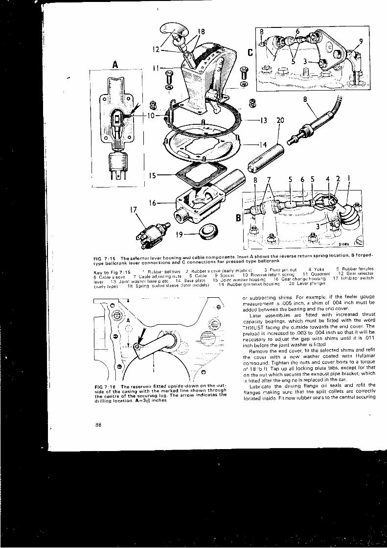
gl 0 t3 20
7
MF I G 7 : 1 5 T h e s e l e c t o r l e v e r h o u s i n g a n d c a b l e c o m p o n e n t s . I n s e t A s h o w s t h e r e v e r s e r e t u r n s p r i n g l o c a t i o n ' B f o r g e d -
i y p e b e l l c r a n k l e v e r c o n n e c t i o n " a n i C c o n n e c t i o n s f o r p r e s s e d - t y p e b e l l c r a n k
K e y t o F i g 7 : 1 5 1 B u b b e r b e l l o w s 2 R u b b e r s l e e v e ( e a r l y m o d e ^ l s ) 3 P i v o l o i n n u t 4 Y o k e 5 R u b b e r t e r r u i e s
6 Cab le s leeve 7 Cab le "a i r r t i "g " r t .
8 Cab le 9 Spacer 10 i leverse re tu rn ip r rnq 11 Ouadrant 12 Gear se lec tor
rever 13 Joint *urn", uu.J' i i j i " ' ' i?
auJ. ir- . ,1" r-s i6i t i i*u.r '" i norr ing 16 Gear ihange housrng 17 lnhibitor switch
(earty rype) '1 8 Sprrng roai" i ' i f""ue (futut-t ioa"f.) 1 9 Rubber grommet housing 20 Lever plunger
F IG 7 : 1 6 The rese rvo i r f i t t ed ups ide -down on t he ou t -i io-" ot i r t t Cai ing wi tn the marked l ine shown throughi f t .
"Lnt ." o i the-secur ing lug. The arrow indicates the
d r i l l i ng l oca t i on . A :3S i nches
88
or subtract ing shims. For example, i f the feeler gauge
measurement is .005 inch, a shim of 004 inch must be
added between the bear ing and the end cover '
Later assembl ies are f i t ted wi th increased thrust
capaci ty bear ings, which must be f i t ted wi th the word
THRUST fac i ng t he ou t s i de t owa rds t he end cove r ' The
preload is increased to .OO3 to 004 inch so that i t wi l l be
necessary to adjust the gap wi th shims unt i l i t is 01 1
i nch be f o re t he j o i n t washe r i s f i t t ed .
Remove the end cover, f i t the selected shims and ref i t
the cover wi th a new washer coated wi th Hylomar
compound. Tighten the nuts and cover bol ts to a torque
o f 18 l b f t . Tap up a l l l o ck i ng p l a te t abs , excep t f o r t ha t
on the nut which secures the exhaust p ipe bracket , which
is f i t ted af ter the engrne is replaced in the car '
Lubr icate the dr iv ing f lange oi l seals and ref i t the
f langes making sure that the spl i t col lets are correct ly
locaied inside. Fi t new rubber seals to the centra l secur ing
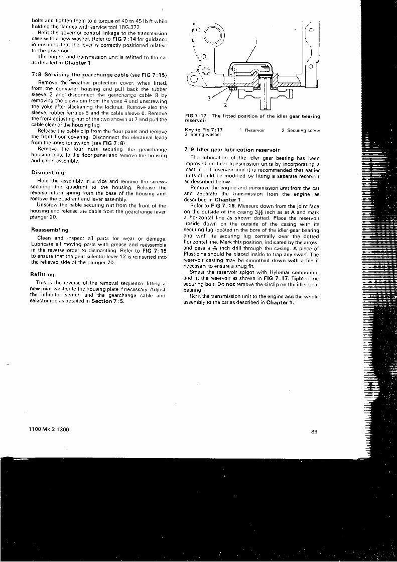
I
bol ts and t ighten them to a torque of 40 to 45 lb f t whi leho ld i ng t he f l anges w i t h se r v i ce t oo l 18G.372 .. Ref i t the governor contro l l inkage to the t ransmissioncase wi th a new washer. Refer to FIG 7 : 14 for guidancein ensur ing that the lever is correct ly posi t ioned re lat iveto the governor.
The engine and t ransmission uni t is ref i t ted to the caras de ta i l ed i n Chap te r 1 .
7 : 8 S e r v i c i n g t h e g e a r c h a n g e c a b l e ( s e e F t G 7 : 1 5 )
Remove the'weather protect ion cover, when f i t ted,f rom the converter housing and pul l back the ruboers l eeve 2 and : d i sconnec l t he gea rchange cab le 8 byremov ing t he c l ev i s p i n f r om the yoke 4 and unsc rewrngthe yoke a f t e r s l acken ing t he l ocknu t . Remove a l so t hesleeve, rubber ferru les 5 and the cable s leeve 6. Removethe f r on t ad jus t i ng nu t o f t he two shown a t 7 and pu l l t hecab le c l ea r o f t he hous ing l ug
Release the cable c l ip f rom the f loor panel and removethe f ront f loor cover ing. Disconnect the electr ical leaosf rom the i nh i b i t o r sw i t ch ( see F IG 7 : 8 ) .
Remove the four nuts secur ing the gearchangehousing plate to the f loor panel and remove the housingand cable assembly.
D i s m a n t l i n g :
Hold the assembly in a v ice and remove the screwssecu r i ng t he quad ran i t o t he hous ing . Re lease t hereverse return spr ing f rom the base of the housing andremove the quadrant and lever assembly.
Unscrew the cable secur ing nut f rom the f ront of thehous ing and re l ease t he cab le f r om the gea rchange l eve rplunger 20.
Reassemb l i ng :
C lean and i nspec t a l l pa r t s f o r wea r o r damage .Lubr icate al l moving parts wi th grease and reassemblei n t he reve rse o rde r t o d i sman t l i ng . Re fe r t o F IG 7 :15to ensure that the gear selector lever 12 is retnserted Intothe re l i eved s i de o f t he p l unge r 20 .
Re f i t t i ng :
This is the reverse of the removal sequence, f i t t ing anew jo int washer to the housing plate i f necessary. Adjustt he i nh i b i t o r sw i t ch and t he gea rchange cab le andselector rod as detai led in Sect ion 7 : 5.
1 1 0 0 M k 2 1 3 0 0
F l G T : 1 7 T h e f i t t e d p o s i t i o n o f t h e i d l e r g e a r b e a r r n gr e s e r v o r r
K e y t o F i g 7 : 1 73 S p r i n g w a s h e r
1 Reservo i r 2 Secur ing screw
7 : 9 l d l e r gea r l ub r i ca t i on rese rvo i r
The lubr icatron of the id ler gear bear ing has beenrmproved on later t ransmrssion uni ts by incorporat tng a'cast
in ' o i l reservoir and i t is recommended that ear l ieruni ts should be modi f ied by f i t t ing a separate reservorras descr ibed below.
Remove the engine and t ransmission uni t f rom the carand separate the t ransmission f rom the engine asdesc r i bed i n Chap te r 1 .
Re fe r t o F IG 7 : 16 . Measu re down f r om the j o i n t f aceon the outs ide of the casing 3i i inch as at A and marka hor izontal l rne as shown dot ted. Place the reservolrupside down on the outs ide of the casing wi th i tssecur ing lug Iocated in the bore of the id ler gear bear ingand wi th i ts secur ing lug centra l ly over the dot tedhor izontal l ine. Mark thrs posi t ion, indicated by the arrow,and pass a $ i nch d r i l l t h rough t he cas ing . A p i ece o fPlastrc ine should be placed inside to t rap any swarf . Thereservoir cast ing may be smoothed down wi th a f i le i fnecessary to ensure a snug f i t .
Smear the reservoir spigot wi th Hylomar compound,and f i t t he r ese rvo i r as shown i n F IG 7 :17 . T i gh ten t hesecur ing bol t . Do not remove the c i rc l ip on the id ler gearbean ng .
Ref i t the t ransmission uni t to the engine and the wholeassembly to the car as descr ibed in Chapter 1.
89
CHAPTER 8
D R I V E S H A F T S A N D S U S P E N S I O N
8 : 18 : 28 : 38 : 48 : 58 : 68 : 78 : 88 : 98 : 1 0
Dr i ve sha f t desc r i p t i onMa in tenanceSe rv i c i ng be l l j o i n t sThe s l i d i ng j o i n tF l ex i b l e d r i ve coup l i ngsUn i ve rsa l j o i n t s
O f f se t sphe re p l unge j o i n t sThe Hyd ro las t i c suspens ionSuspens ion l ub r i ca t i onSe rv i c i ng t he suspens ion sys tem
8 :1 D r i ve sha f t desc r i p t i on
The componen ts o f t he f r o r r t suspens ion and d r i vesha f t assemb l i es a re c l ea r l y shown i n F IG 8 :1 . l t w i l l beseen that the dr ive shaf t 74 has. at i ts outer end. theconstant veloci ty bel l jo int which is protected by therubbe r boo t 75 , and a t i t s i nne r end t he coup l i ng f l ange76 wh i ch i s cove red by t he sea l J7 ove r t he sp l i ned j o i n t .
The hem isphe r i ca l i n t e r i o r o f t he Ha rdy Sp i ce r be l lj o i n t and t he ex te r i o r o f t he i nne r ba l l r ace have s i xg rooves mach ined i n l i ne w i t h t he sha f t ax i s and a ba l lcage carry ing s ix steel bal ls is interposed between thetwo. The steel bal ls engage the grooves of both membersto key them together and at the same t ime to a l low,themembers to h inge f reely upon each other. Both the jo intassemb ly and t he sp l i ned s l i d i ng a re packed w i t h g reaseand, as ment ioned. enclosed in rubber boots.
8 :2 Ma in tenance o f d r i ve sha f t s
The rubber boots enclosing the constant veloci tyj o i n t s shou ld be exam ined pe r i od i ca l l y and i f t he re i s anysign of damage or deter iorat ion they should be renewedw i t hou t de lay .
l f a boo t becomes f au l t y l ub r i can t w i l l be l os t and g r i tf r om the road w r l l en te r t he j o i n t . l t w i l l t hen be necessa ryto remove the jo int f rom the shaf t and to d ismant le the
1 1 0 0 M k 2 1 3 0 0
8 : 1 1 S e r v i c i n g t h e h u b s8 : 1 2 T h e a r c h s p r i n g8 : 1 3 S t e e r i n g a n g l e s8 : 14 The sub f r ames8 : 1 5 D i s p l a c e r u n i t s8 : 1 6 R a d i u s a r m s8 : 1 7 S w i v e l h u b s8 : 1 8 A n t i - r o l l b a r a n d a u x i l i a r y s p r i n g s8 : 1 9 F a u l t d i a g n o s i s
assemb ly f o r i nspec t i on . l f a boo t i s damaged i n t hecourse of workshoo oDerat ions and no di r t has enteredthe jo int a new boot may be f i t ted as descr ibed inSec t i on 8 :3 w i t hou t d i sman t l i ng t he j o i n t , a l t houghthe dr ive shaf t must be removed f rom the car and thes l i d i ng j o i n t r e l eased . The be l l j o i n t mus t be packed w i t hDuckham 's MB g rease (BMC pack AKF 1457 )
8 : 3 S e r v i c i n g b e l l j o i n t s
The cons tan t - ve l oc i t y be l l j o i n t s may be removed e i t he rfor replacement as a uni t or to have a serv ice k i t f i t ted.Unde r no c i r cums tances mav i nd i v i dua l comoonen tsbe rep laced i n t he be l l j o i n t assemb ly .
A f t e r r emov ing t he d r i ve sha f t ( see Sec t i on 8 :17 )c l ean i t ca re fu l l y and moun t r t cen t ra l l y i n a v i ce and he ldbetween sof t jaws. Pr ise of f the c l ips hold ing the rubberboo t s as shown i n F IG 8 : 2 and pu l l back t he boo t .
The bel l jo int is removed f rom the shaf t by hold ing theassemb ly ve r t i ca l l y as shown i n F IG 8 :3 and g i v i ng t heedge of the outer race a sharp tap wi th a sof t faced mal let .This should contract the round sect ion spr ing located rn adeep groove at the extreme end of the shaf t and enablethe jo int to be drawn from the shaf t . . l t should not benecessary to use heavy blows for th is operat ion.
9 1
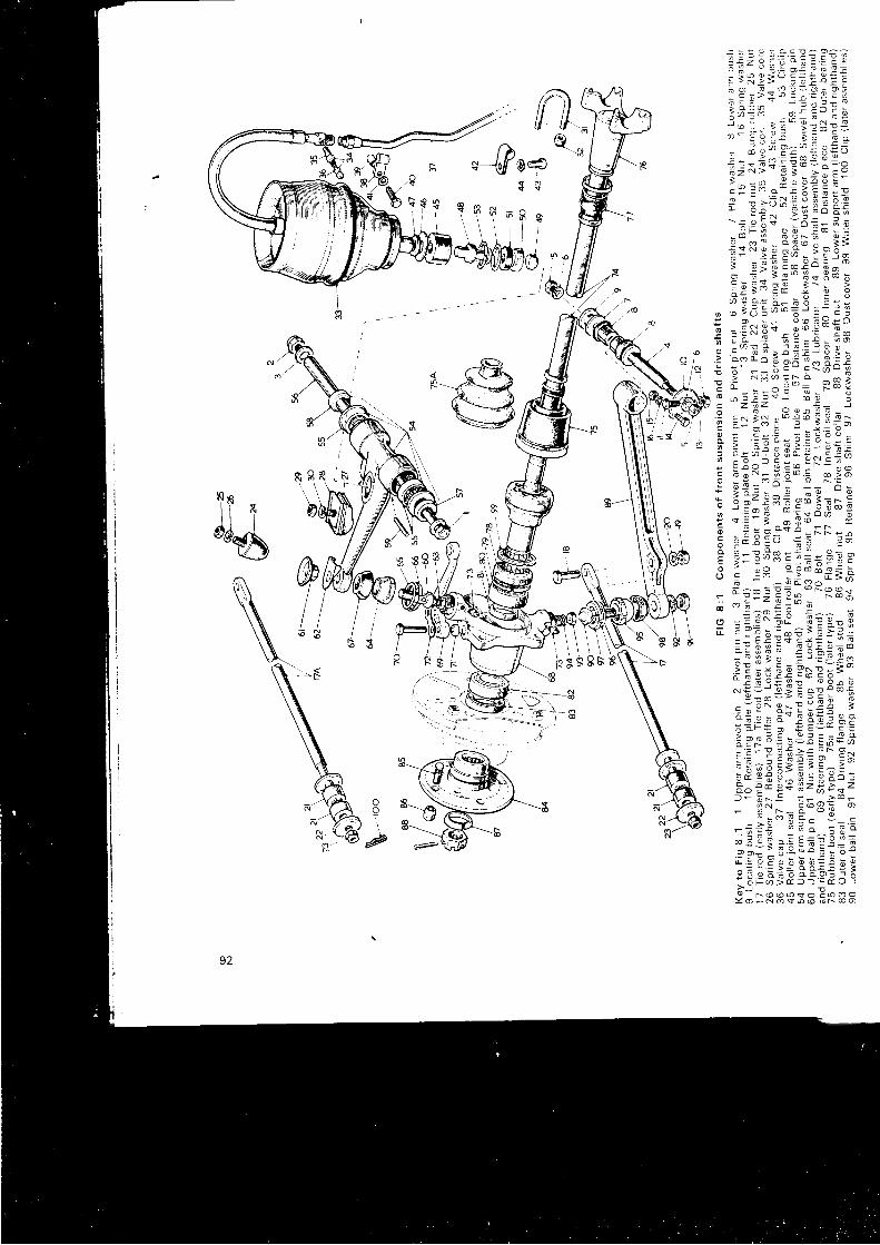
\ ; " , 2 2 i ! ? E : : ; :i i : s i - i ' ; t s t :: g r s s s ! ; - = : - 3 [a " ) = ' - : : - o c i
J : : q i : " ; E s ; ;- d g ' P ; " ' E 3 F c , :i : o i r = ! 3 j 3 = - o! Z - t
- ; ; _ ; . g 3
i : ! 3 - e * : E ; : .; t ; ? t ; ; m s A ;- ; :
I + ' o 6 E ; I f i: " n : ' i [ E [ ' ; =; - - i t = '3 : ; : : 3I r i - * ip- !* ; ' :
,3E; '= .e ;5 !e i : !; : a: i=u i? i : ; ;i ;i:i gE8:-.-:+; ^ : - u ' F E I - * i
| ;= iz=: , lg . - ;e i : 1 9 s - ! - ) ! * BF g i ; i r ! H ! 3 i =e 1 E ? - E : l E l ! i 6E : !K ; : E ; a s i s: 9 + 5 - i = ; o h- 1 * z 6 0 = ^ , S : - - - u o c o o : ' s a o ! : =
; - = ? 3 r i r 5 3 * EE = ; 3 - 9 i ! - - * E
i s E E 3 5 - i E - - : sF !=E , ' s i I * :Fess i ; 3 3 e : : f E s
# ^ - = € i * 6 H o o *
: ; E = z . E ; 3 o r @ d
s : i E N - o i 6 9 9 o 9I : 9 E b - - 6 t F 5 i ;
tE E !:";!E3lII E : x I Q P l l : 3 " '
L o : : < - ' - u : 9
- i 3 j E s ; * ; i s ;' i ; ;E;: g€3 -;E o F = o , : b - * c ;
i E s B E ; e - 3 F f i J . oi i - E E i : E 3 - P r; * a 3 : i E ; a ^ > " '
a5i3 Es ft : ;3?t:- g*;= _a;afi-i. t i * I I
. -^qe-e: ; g : a E i : E : = E
!E i;i5eeF::;9 - n o o o v o E o o o
Y o F N o s f n @ o f @ o
i T i,d6
fI
92
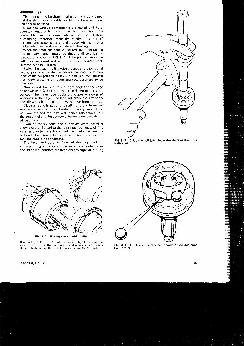
Disman t l i ng :
The jo int should be dismant led only i f i t is consideredthat i t is st i l l in a serv iceable condi t ion, otherwise a newuni t should be f i t ted.
Since the var ious componenls aIe mated and haveoperated together i t is important that they should bereassembled in the same relat ive posi t ions. Beforedismant l ing, therefore, mark the re lat ive posi t ions ofthe inner and outer races and the cage wi th paint or amarker which wi l l not wash of f dur ing c leaning.
When the shdTt has been wi thdrawn the inner race isf ree to swivel and should be t i l ted unt i l one bal l isr e l eased as shown i n F IG 8 :4 . l f t he j o i n t i s s t i c ky t hebal l may be eased out wi th a sui table pointed tool .Remove each bal l in turn.
Sw ive l t he cage i n t o l i ne w i t h t he ax i s o f t he j o i n t un t i ltwo opposi te e longated windows coincide wi th twolands o f t he be l l j o i n t as i n F IG 8 : 5 . One l and w i l l f a l l i n t oa window al lowing the cage and race assembly to bel i f ted out ,
Now swivel the inner race at r ight angles to the cageas shown i n F IG 8 :6 and ro ta te un t i l two o f t he l andsbetween the inner race t racks are opposi te e longatedwindows in the cage. One land wi l l drop into a windowand al low the inner race to be wi thdrawn from the cage.
Clean al l parts in petro l or paraf f in and dry. In normalserv ice the wear wi l l be dist r ibuted evenly over a l l thecomponen ts and t he j o i n t w i l l r ema in se rv i ceab le un t i lthe amount of end f loat exceeds the acceptable maximumof .025 inch.
Examine the s ix bal ls , and i f they are worn, p i t ted orshow signs of f lat tening the jo int must be renewed. Theinner and outer race t racks wi l l be marked where thebal ls ro l l , but should be f ree f rom indentat ion and themarking should be consistent .
The inner and outer surfaces of the cage and thecorresponding surfaces of the inner and outer racesshould appear pol ished but f ree f rom any s igns of p ick ing
F I G 8 : 2 F i t t i n g t h e c l i n c h i n g c l i p s
K e y t o F i g 8 : 2 1 P u l l r h e f r e e e n d t i g h r l y b e t w e e n r h etabs 2 Ho ld in pos i t ion and secure w i lh { ron l tabs3 Fo ld c l ip back over the fo lded tabs and secure the c l ip end
1 1 0 0 M k 2 1 3 0 0
F I G 8 : 4 T i l t t h e i n n e r r a c e t o r e m o v e o r r e p l a c e e a c hb a l l i n t u r n
93
F I G 8 : 3 D r i v e t h e b e l l j o i n t f r o m t h e s h a f t a t t h e p o i n tind ica ted
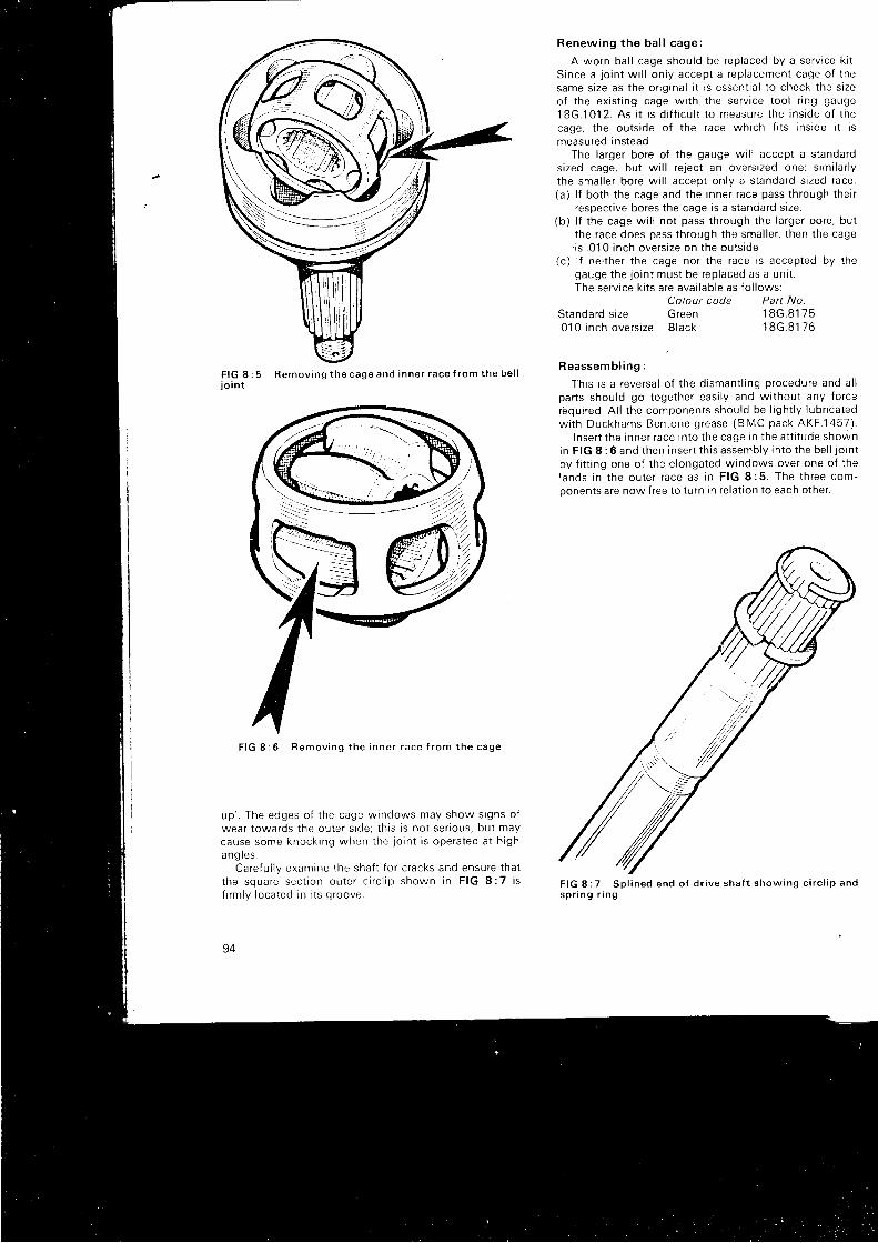
Renew ing t he ba l l cage :
A worn bal l cage should be replaced by a serv ice k i t .S rnce a j o i n t w i l l on l y accep t a r ep lacemen t cage o f t hesame s i ze as t he o r i g i na l i t r s essen t i a l t o check t he s i zeo f t he ex i s t i ng cage w i t h t he se rv i ce t oo l r i ng gauge18G.101 2 . As i t i s d i f f i cu l t t o measu re t he i ns i de o f t hecage, the outs ide of the race which f i ts ins ide i t ismeasured instead.
The larger bore of the gauge wi l l accept a standards i zed cage . bu t w i l l r e j ec t an ove rs i zed one ; s im i l a r l ythe smal ler bore wi l l acceot onlv a standard s ized race.(a ) l f bo th t he cage and t he i nne r r ace pass t h rough t he i r
respect ive bores the cage is a standard s ize.( b ) l f t he cage w i l l no t pass t h rough t he l a rge r bo re , bu t
the race does pass through the smal ler , then the cage- is .01 0 inch overs ize on the outs ide.
( c ) l f ne i t he r t he cage no r t he race i s accep ted by t hegauge t he j o i n t mus t be rep laced as a un t t .The serv ice k i ts are avai lable as fo l lows:
Colour code Part No.Standard s ize Green.01 0 i nch ove rs i ze B lack
1 8 G . 8 1 7 51 8 G . 8 1 7 6
F I G 8io i n t
5 R e m o v i n g t h e c a g e a n d i n n e r r a c e { r o m t h e b e l lR e a s s e m b l i n g :
This is a reversal of the dismant l ing procedure and al lpa r t s shou ld go t oge the r eas i l y and w i t hou t any f o r cerbqu i r ed . A l l t he componen ts shou ld be l i gh t l y I ub r i ca tedw i t h Duckhams Ben tone g rease (BMC pack AKF .1457 ) .
I nse r t t he i nne r r ace i n t o t he cage i n t he a t t i t ude shownin F IG 8 :6 and t hen i nse r t t h i s assemb ly i n t o t he be l l j o i n tby f i t t ing one of the elongated windows over one of thel ands i n t he ou te r r ace as i n F IG 8 :5 . The t h ree com-Donents are now free to turn in re lat ion to each other.
F I G 8 : 7 S p l i n e d e n d o f d r i v e s h a f t s h o w i n g c i r c l i p a n ds p r i n g r i n g
F I G 8 : 6 R e m o v i n g t h e i n n e r r a c e f r o m t h e c a g e
up ' . The edges o f t he cage w indows may show s i gns o fwear towards the outer s ide; th is is not ser ious, but maycause some knock ing when t he j o i n t i s ope ra ted a t h i ghang l es .
Ca re fu l l y exam ine t he sha f t f o r c racks and ensu re t ha tt he squa re sec t i on ou te r c i r c l i p shown i n F IG 8 :7 i sf i rm l y l oca ted i n i t s g roove
94
t
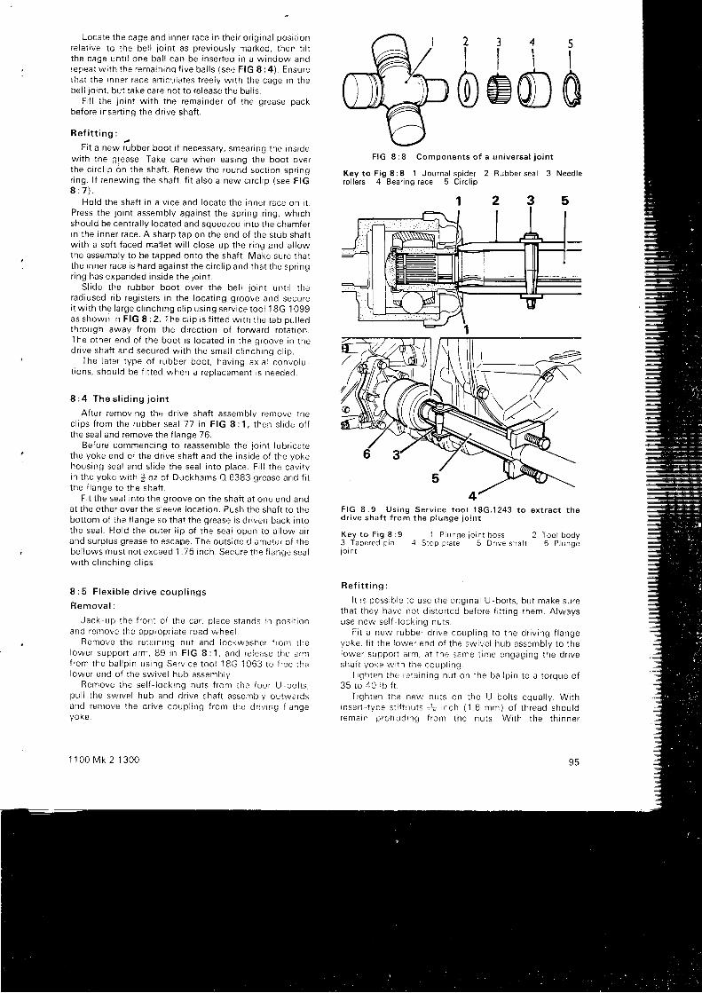
Loca te t he cage and i nne r r ace i n t he i r o r i g i na l pos i t r onrelat ive to the bel l jo int as previously marked, then t i i tt he cage un t i l one ba l l can be i nse r t ed i n a w indow and|epea t w i l h t he rema in i nq f i ve ba i l s ( see F IG 8 :4 ) . Ensu reihat the inner race ar t icuiates l reely wi th t i - re cage in thebel l io int , but take care not to re lease the ba! !s.
Fi l i the jo int wi th the remainder of the grease packbefore insert ing the dr ive shaf t .
R e f i t t i n g :
Fi t a new f ibber boot i f necessary, smeanng t le Insrdew i t h t he g fease . Take ca re when eas ing t he boo t ove rt he c i r c l i p on t he sha f t . Renew the round sec t i on sp r i ngr i ng . l f r enew ing t he sha f t . f i t a l so a new c i r c l i p ( see F IG8 : 7 ) .
Ho ld t he sha f t i n a v i ce and l oca te t he i nne r r ace on i t .P ress t he l o i n t assemb ly aga ins t t he sp r i ng r i ng , wh i chshould be centra l ly located and squeezed into the chamferi n t he i nne r r ace . A sha rp t ap on t he end o f t he s tub sha f twi th a sof t faced mal let wi l l c lose up the r ing end al lowthe assembly to be tapped onto the shaf t . Make sure thatt he i nne r r ace i s ha rd aga ins t t he c i r c l i p anc i t ha t t he spnngr i ng has expanded i ns i de t he 1o in t .
S l i de t he rubbe r boo t ove r t he be l l j o i n t un t i l t heradiused r ib registers in the locat ing groove and securei t w i t h t he l a rge c l i nch ing c l i p us i ng se rv i ce t oo l 1 8G .1 099as shown i n F IG 8 :2 . The c l i p i s f i t t ed w i t h r he t ab pu l r eothrough away f rom the di rect ion of forward rotat ion.The o the r end o f t he boo t i s l oca ted i n t he g roove i n t hed r i ve sha f t and secu red w i t h t he sma l l c l i n ch ing c l i p .
The l a t e r t ype o f r ubbe r boo t , hav ing ax i a l convo lu -t i ons , shou ld be f i t t ed when a r ep lacemen t i s needed .
8 : 4 T h e s l i d i n g j o i n t
Af ter removing the dr ive shaf t assembly remove thec l i ps f r om the rubbe r sea l 77 i n F IG 8 : 1 , t hen s l i de o f fthe seal and remove the f lange 76.
Before commencing to reassemble the jo int lubr icatethe yoke end of the dr ive shaf t and the inside of the yokehous ing sea l anc i s l i de t he sea l r n to p l ace . F i l l t he cav i t yi n t he yoke w i t h j oz o f Duckhams O 6383 g rease and f i tt he f l ange t o t he sha f t .
F i t the seai into the groove on the shaf t at one end andat the other over the s lee' re locat ion. Push the shaf t to thebottom of the f lange so that the grease is dr iven back intothe sea l . Ho ld t he ou te r l i p o f t he sea l open t o a l l ow a r rand su rp i us g ! ' ease t o escape . The ou t s i de d i ame te r o f t hebe l l ows mus t no t exceed 1 .75 i nch . Secu re t i r e f l anqe sea rw i t h c l i nch ing c l i ps .
8 : 5 F l e x i b l e d r i v e c o u p l i n g s
R e m o v a l :
Jack -up t he f r on t o f t he ca r , p l ace s tands rn pos i t i onand remove t he app rop r i a te r oad w .hee i .
Remove t he re ta i n i ng nu t and l ockwasne r t r o r r r r . ! i el owe r suppo r t a rm , 89 i n F IG 8 :1 , and re i ease t he . f n if r om the ba l l p i n us i ng Se rv i ce t oo l 18G.1063 t o f ; ' ee i hel owe r end o f t he sw i ve l hub assemb ly .
Remove t he se l { - l ock i ng nu t s f r om i he i ou r U -bo l t s .pu l l t he sw i ve l hub and d r i ve sha f t asse i r r b l y ou t l va rCsand remove t he d r i ve coup i i ng f i ' om the d r : v i ng f l angeyoke .
1 1 0 0 M k 2 1 3 0 0
i i i ioemCIF I G 8 : 8 C o m p o n e n t s o f a u n i v e r s a l j o i n t
Key to F ig 8 :8 1 Journa l sp ider 2 Rubber sea l 3 Need lero l le rs 4 Bear ing race 5 C i rc l ip
1 2 3 5
F I G 8 : 9 U s i n g S e r v i c e t o o l 1 8 G . 1 2 4 3 t o e x t r a c t t h ed r i v e s h a f t f r o m t h e p l u n g e j o i n t
K e y t o F i g 8 : 9 1 P l u n g e j o i n t b o s s 2 T r : o l b o d y3 T a p e r e d p i n 4 S t o p p l a t e 5 D r r v e s h a f t 6 P l u n q el o r n t
R e f i t t i n g :
I t r s poss ib l e t o use i he o r i g i na l U -bo l t s , bu t make su retha t t hey have no t d i s t o r t ed be to re f i t t i ng t hem. ,A lwaysuse now se l f l o ck i ng nu t s .
F i t a new rubbe r d r i ve coup l i ng t o t he d r i v i ng f l angeyoke , f i t t he i owe r end o f t he s r , v i ve l hub assemb ly t o t heiowe r suppo r t a r rn , a t t he same t ime engag ing t he d r r vesha{t yoke rn", i , ;h the coupl ing.
T ig ;h ten t he : r e ta i n i ng nu t on t he ba i l p i n t o a t o rque o f35 to 4;1 ib { t
T rqh ten i he new nu t s on t he U ,bo l t s equa l l y . W i t hi nse r i - t ' vpe s t i f i nL r t s , 1o i nch (1 .6 mm) o f t h read shou ldrema in p ro l r d rng f r o r -n t he nu t s . Wr th t he t h i nne r
9 5
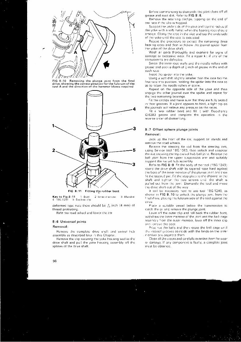
d r i v e . s h o w i n g t h e c o r r e c t p o s i t i o n f o r t h e f u l c r u m o f t h et o o l A a n d t h e d i r e c t i o n o f t h e h a m m e r b l o w s r e o u i r e d
F I G 8 : 1 1 F i t t i n g t h e r u b b e r b o o t
K e y t o F i g 8 : 1 1 1 B o o t 2 I n n e r m e m b e r 3 M a n d r e l4 1 8 G . 1 2 5 1 5 E n d l e s s c l i p
de fo rmed t ype nu t s t he re shou ld be $ i nch (4 mm) o ft h read p ro t r ud ing .
Re f i t t he r oad whee l and l owe r t he ca r .
8 : 6 U n i v e r s a l j o i n t s
R e m o v a l :
Remove t he comp le te d r i ve sha f t and sw i ve l hubassemb ly as desc r i bed l a t e r i n t h i s Chap te r .
Remove t he c l i p secu r i ng t he yoke hous ing sea l t o t hed r i ve sha f t and pu l l t he yoke hous ing assemb ly o f f t hesp l i nes o f t he d r i ve sha f t .
96
Be f o re commenc ing t o d i sman t l e t he j o i n t c l ean o f f a l lg rease and road d i r t . Re fe r t o F IG 8 :8 .
Remove t he re ta i n i ng c i r c l i p s , t app ing on t he end o ft he race i f t he c l i p i s t r apped .
Suppo r t t he unc ie r . s i de o { t he yoke and t ap t he rad ius o ft he yoke w i t h a so f t ma l i e t when t he bea r i ng race shou ldemerge . C lamp the race i n t he v i ce and t ap t he unde rs i deo f t he yoke un t i l t he r ace i s ex t r ac ted .
Repea t t he p rocedu re t o ex t r ac t t he rema in i ng t h reebea r i ng races and t hen w i t hd raw the j ou rna i sp i de r f r omthe yoke o f t he d r i ve sha f t .
Wash a l l pa r t s t ho rough l y and exam ine f o r s i gns o fdamage o r excess i ve wea r . F i t a r epa i r k i t i f any o f t hecomponen ts a re de fec t i ve .
Smear t he i nne r r ace wa l l s and t he need le r o l l e r s w i t hg rease and pack a dep th o f ] i n ch o f g rease i n t he end o feach race .
I nse r t t he sp ide r i n t o t he yoke .Us ing a so f t d r i f t s l i gh t l y sma l l e r t han t he race t ap t he
f i r s t r ace rn to pos i t i on , ho ld i ng t he sp ide r i n t o t he race soas t o r e ta i n t he need le r o l l e r s i n p l ace .
Repea t on t he oppos i t e s rde o f t he yoke and t henengage t he o the r j ou rna l ove r t he sp ide r and repea t f o rt he two remarn ing bea r rngs .
F i t t he c i r c l i p s and make su re t ha t t hey a re f u l l y sea tedin t he i r g rooves . l f a l o i n t appea rs t o b tnd , a l i gh t t ap onthe l ou rna l s w r l l r e l i eve any p ressu re on t he races .
F i t a new rubbe r boo t and f i l l i t w i t h Duckham 'sO .6383 g rease and comp le te t he ope ra t i on i n t hereve rse o rde r o f d i sman t l i ng .
8 : 7 O f f se t sphe re p l unge j o i n t s
R e m o v a l :
Jack up t he f r on t o f t he ca r , suppo r t on s tands andremove t he road whee l s .
Re lease t he s tee rng t i e r od f r om the s tee r i ng a rm ,us ing Se rv i ce t oo l 18G.1063 , t hen un lock and unsc rewthe nu t secu r i ng t he t op sw i ve l hub ba l l j o i n t . Re lease t heba l l l o i n t f r om the uppe r suspens ion a rm and su i t ab l ysuppo r t t he sw i ve l hub assemb ly .
R e f e r t o F I G I : 9 . F i t r h e b o d y o f t h e t o o l ( 1 8 G . 1 2 4 3 )round t he d r i ve sha f t w i t h i t s t ape red nose ha rd aga ins tt he boss o f t he i nne r member o f t he p l unge . 1o in t and t henf i t t he t ape red p i n . F i t t he s top p l a te 1o t he channe l i n t hesha f t and t i gh ten t he two sc rews un t i l t he sha f t i spu l l ed ou t f r om the j o i n t . D i sman t l e t he t oo l and movethe d r i ve sha f t ou t o f t he way .
i t w i l l be necessa ry nex t t o use t oo l ' 1
8G .1240 , ass h o w n i n F I G 8 : 1 0 t o u n l o c k t h e p l u n g e j o i n t f r o m t h ef i na l d r i ve , p l ac i ng t he f u l c rum s i de o f t he t oo l aga ins t t hedi lve.
P iace a su i t ab le vesse l be low t he t r ansm iss i on t oca t ch t he o i l and remove t he p l unge j o i n t .
Leve r o f f t he ou te r c l i p and ro l l back t he rubbe r boo t ,w r t hd raw the i nne r member o f t he j o i n t and t he ba l l - cageassemb ly f r om the ou te r member , l eve r o f f t he i nne r c l i pan i i r en rove i he boo t
P i i se cu t t he ba l l s and t hen ro ta te t he ba l l - cage un t i lt he i n t e rna ! J i ( ) oves co inc i de w i t h t he l ands on t he i nne rn rember and sepa ia te t hem
Clean a l l t he p i eces and ca re f u l l y exam ine t hem f o r wea ro r damage . l f any componen t i s f au l t y , a comp le te j o i n tmus t be ob ta rned .
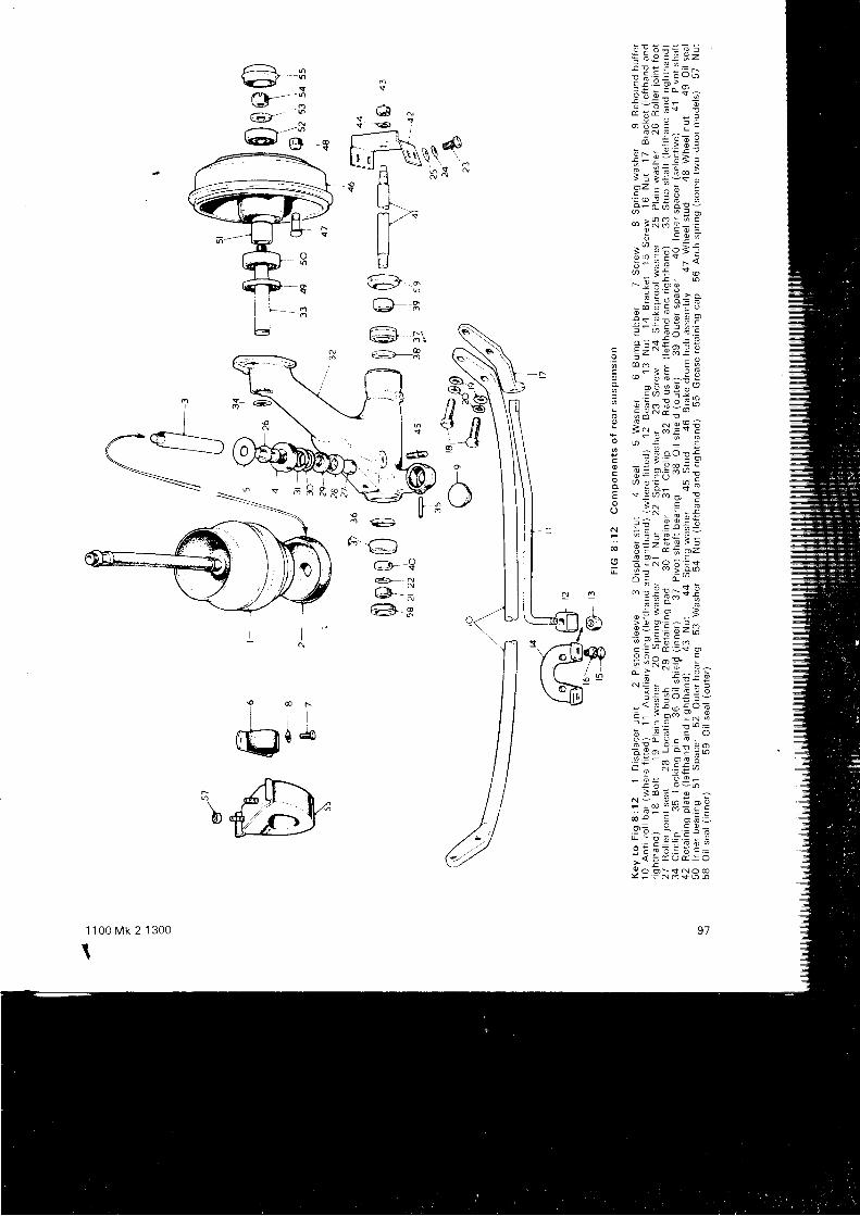
"E: E a€ n:= 6 Y a E 6 , 2i : : i 3 = -: E - = ^ 9 " -; : ; ; ' * s ?x : : ! !
: - = - F O
- * - E i EO E Y R S
; - - o ; i !i I P - 3 B oq * E E g - :> I < i ; " $ o? z c l 3 E
' = , . o I ? I. + : a ; e l J
- ; R E E ' !O L O ^
: c o 6 -
- - ' b ; o - to o € - s i: - : G r \
r Y : o o
! i ;B ; r: - 9 ; - t r -
! s a i o 9 : r! - ! - E ; ' ; . =
J v / 6 ^ O r- c " ^ ;
. 3 ; X 5 * i E9 f' E o - , E E n6 o d b ^ : Eo - ' 9 . ? 1 . 9 o "
v ) . = - v . ^6 ; : - 9 o S [ ih 5 g i . i d ; .
i i : " ses?v O E _ z
I ; 6 o o o : -- x < =
E - ! ; s g ; :O , i - . = " , ^ cg ! o - + - -F s Y U ) ; - !
X 5 N . ! !v - N : ' +
r u E E . = o ? :: : : : * E ; q- 3 - E ' d 5 - zo * 3 i o ; ! q
o : + :- : ; E 5 + ;d G -
' € i P * B> O O ; ^ f -
3 = : ; E Z Ua Y ' s ; \ - a
c l o d 3 s oo o ^ - c
c : ' - - F ^ E ;; P t = ! 9 0
. = o ! i - : ^ o *! - I Po i ' r U
b - 6 E o: ; L : c o
" ' . -: 6 ^ i 0 9 6 : ;o . = r ^ ^ O O ;
: c ! . ;' \ f , : - '- i : 3 3 ;
3 o E - o -N - o , ^ ; ^ ; iF : @
@ i l ; : ' -' ' : - : * - c
o ! : o 6 =
. 9 E ^ : ^ : ; G
o : h 7 9 * E -P : t ; ; - , : c A
o o E r n < r o oY - - N o $ o o
\|1, NS d
{ @ ;
r
j@
l ' \ 6\c/ :c - ;
Gv' :C e $
G - nl.-! o\=t o
<-t--;l?-_)-6
€.- lei
tA r--rt : J
@'-9@ _ *
@=;@ r
\fu"971 1 0 0 M k 2 1 3 0 0
\

F I G 8 : 1 3 S e c t i o n v i e w o f H y d r o l a s t i c u n i t
K e y t o F i g 8 : 1 3 A l n t e r c o n n e c t i n g p i p e B R u b b e rs p r i n g C D a m p e r b i e e d D B u t y l l r n e r E T a p e r e dp i s t o n F D a m p e r v a l v e s G F l u i d s e p a r a t i n g m e m b e rH R u b b e r d i a p h r a g m J T a p e r e d c y l i n d e r
Reassemb ly :
F i t an end less c l i p ove r t he i nne r neck o f a new rubbe rboo t w i t h i t s chamfe r t owa rds t he i ns i de . Ho ld t he i nne rmember o f t he j o i n t i n a so f t - l awed v i ce , as shown i nF I G I : 1 1 a n d i n s e r t t h e m a n d r e l o f S e r v i c e t o o l 1 8 G . 1 2 5 1 .Coa t l i be ra l l y w i t h Ru -G lyde , p re fe rab l y wh i l e weanngrubbe r g l oves , o r w i t h Teepo l and s l i de t he boo t downthe mand re l , push ing i t home on t o t he boss us i ng t hes leeve o f t he t oo l . C lean o f f a l l su rp l us l ub r i can i f r omcomponen ts and t oo l s .
Assemb le t he cage and ba l l s i n r eve rse o rde r o f d i s -man t l i ng ensu r i ng t ha t t he l ong - t ape red end o f t he ba l lcage faces the dr ive shaf t end.
Pack 50 cc o f Ben tone g rease i n t o t he ou te r memberand f i t t he i nne r member and ba l l cage assemb ly . F i t t heboo t and secu re i t w i t h a c l i nch ing c l i p .
F i t t he wa te r sh re l d t o t he po l i shed boss o f t he l o i n tw i t h t he d i shed s i de t owa rds t he f i na l d r i ve .
Lub r i ca te t he sp l i nes and push t he p l unge j o i n t r n un t i lt he sp r i ng r i ng i s f u l l y engaged .
Engage l ow gea r , o f f e r u p t he d r i ve sha f t t o t he j o i n t a ndengage t he sp l i nes by t u rn i ng t he d r i ve f l ange . Tap t heassemb ly home . us i ng a ma l l e t on t he end o f t he d r i veshaft .
Re f i t t he ba l l l o i n t on t he t op sw i ve l hub and t hes tee r i ng t i e r od , us i ng a new l ockwashe r , and t i gh ten t o35 -40 and 25 I b f t r espec t i ve l y .
F i t t he r oad whee l s , l owe r t he ca r and f i l l t he powerun i t w i t h a sDec i f i ed o i l .
98
8 : 8 T h e ' H y d r o l a s t i c ' s u s p e n s i o n
Th i s sys tem o f veh i c l e suspens ion i s des igned t o r educepi tching and ro l l ing and, therefore, to g ive a smooth f latr ide wi th the best possib le handl ing character is t ics. Thefront suspension is shown in the exploded v iew of FIG8 :1 together wi th the dr iv ing shaf ts, and the componentso f t he rea r suspens ion a re shown i n F IG I : 12 .
The system consists of two f ront and 1wo rear d is-p l ace r un i t s , wh i ch a re shown i n sec t t on rn F IG 8 :13 ,i n t e r coup led l ong i t ud ina l l y t h rough t he p i pes A . Eachuni t consists of a p iston E pressing on a diaphragm Hhoused i n a s t ee l cas i ng d i v i ded i n t o an uppe r and l owe rchamber separated by the member G and incorporat inga conical spr ing of compressed rubber.
An upward movement of a f ront wheel forces the pistonto push t he d i aph ragm upwards and t he i nc reas ingpressure forces f lu id up into the top chamber. Thisde f l ec t s t he rubbe r sp r i ng and t he resu l t an t p ressu rei nc rease f o r ces f l u i d t h rough t he i n t e r connec t i ng p tpein to t he rea r d i sp l ace r un i t whe re t he i nco rn i ng f l u i dpushes the diaphragm, and rar i th i t the piston. dow,nwarcsand so ra ises the rear end of the car io an exle:11 s i in i lart o t he f r on t . As t hese movemen ts a re v i r t ua l l y s imu l t an -eous the resul t is that the car r ides the obstruct ion wi thl i t t l e o r no p i t ch i ng mo t i on o f t he body . The ac t i on o f t hesuspens ion i s t he same when t he rea r whee l s encoun te ra bump . These movemen ts a re shown d iag rammat i ca l l yi n F I G 8 : 1 4 .
The f l u i d used i s a m i x tu re o f wa te r and a l coho l w i t han an t i - co r ros i ve add i t i ve .
The f r on t suspens ion a l so compr i ses uppe r and l owe ra rms o f unequa l l eng th 54 and 89 i n F IG 8 :1 p i vo ted i nthe s idemembers of the f ront subframe. and wi th rneou te r ends a t t ached by ba l l j o i n t s t o t he sw i ve l hubs 68 ,
The rear suspension, in addi t ion to the hydrolast icun i t s , cons i s t s o f i ndependen t t r a i l i ng a rms 32 i n F IG8 : 1 2 , a u x i l i a r y s p r i n g s 1 1 a n d a n a n t i - r o l l b a r ' 1 0 . R u b b e ra rch sp r i ngs 56 a re used i n p l ace o f i t ems 10 and 11 onla te r mode l s .
8 : 9 S u s p e n s i o n i u b r i c a t i o n
Th i s cons i s t s o f occas iona l a t t en t i on t o t he g reasen ipp les on t he two sw i ve l j o i n t s . Jack -up t he f r on t o f t heca r t o t ake t he l oad o f f t he j o i n t s . Make su re t ha t t hen ipp les 73 a re c l ean and no t b l ocked w i t h d i r t . l f t hesw ive l knuck les a re a l r eady f u l l o f g rease ve ry I i t t l e canbe forced in.
8 : 1 0 S e r v i c i n g t h e s u s p e n s i o n s y s t e m
In v i ew o f t he cond i t i ons imposed by t he Hyd ro las t i csystem of suspension there are several serv ic ing opera-t i ons wh i ch mus t no rma l l y be l e f t t o a qua l i f i ed Se rv i ceStatron as i t is not possib le to perform them withoutdepressur iz ing the system before commencement andp ressu r i z i ng on comp le t i on o f t he wo rk ; and t he e l abo ra teequ rpmen t r equ i r ed f o r t h i s i s no t usua l l y ava i l ab l e t o t heowne r -ope ra to r . Such ooe ra t i ons i nc l ude t he remova l o ft he f r on t sub f rame , t he uppe r suspens ion a rms , sw i ve lhubs and t he d i sp l ace r un r t s and rea r sub f rames .
l f t he home ope ra to r f ee l s t ha t he i s qua l i f i ed t o ca r r you t t hese o r s im i l a r j obs i t i s qu i t e pe rm iss i b l e f o r h im t ohave the system professional ly depressur ized before hed r i ves t he veh i c l e home to De r fo rm the t asks -and back
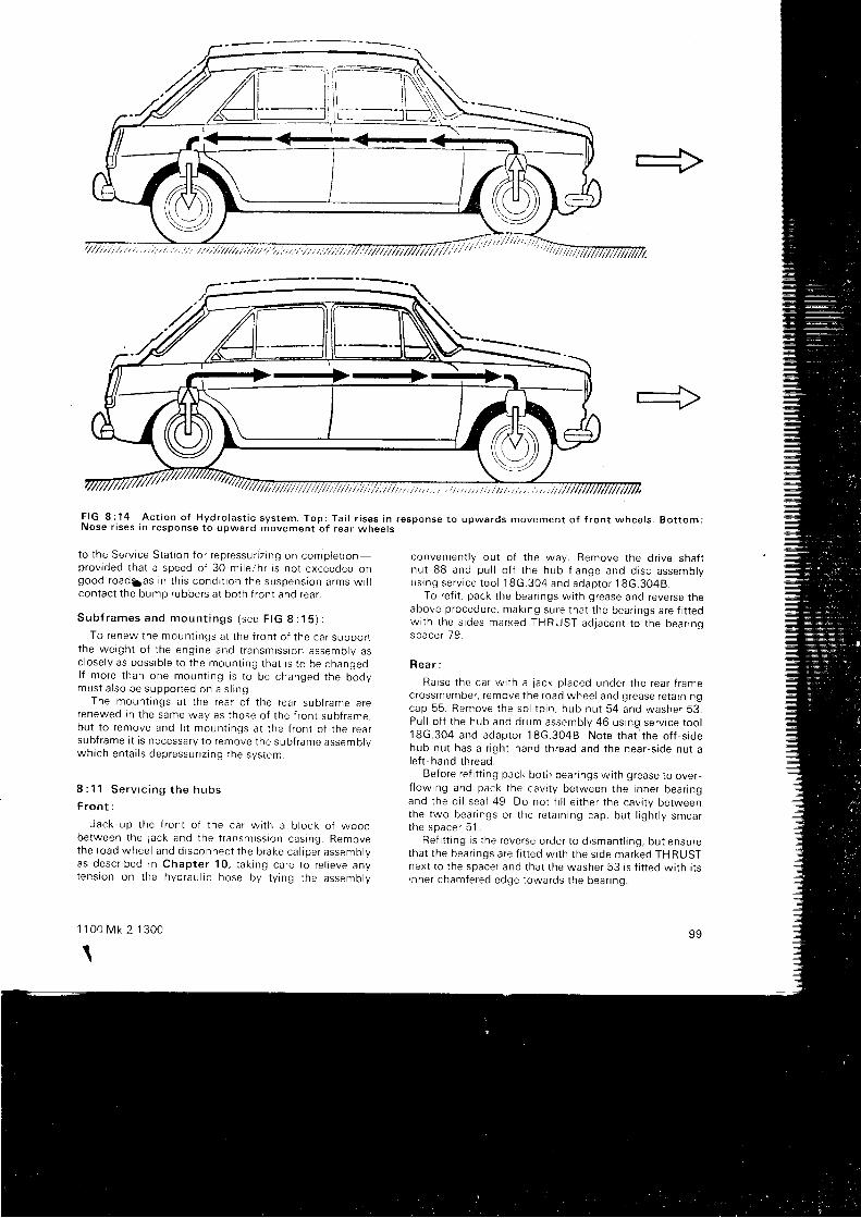
ffit,'"/"'
F I G 8 : 1 4 . A c t i o n o f H y d r o l a s t i c s y s t e m . T o p : T a i l r i s e s i n r e s p o n s e t o u p w a r d s m o v e m e n t o f f r o n t w h e e l s . B o t t o m :N o s e r i s e s i n r e s p o n s e t o u p w a r d m o v e m e n t o f r e a r w h e e l s
t o t he Se rv i ce S ta t i on f o r r ep ressu r i z i ng on comp le t i onprovrded that a speed of 30 mi le/hr is not exceeded ongood road5as i n t h i s cond i t i on t he suspens ion a rms w i l lcon tac t t he bump rubbe rs a t bo th f r on t and rea r .
S u b f r a m e s a n d m o u n t i n g s ( s e e F I G 8 : 1 5 ) :
To renew the moun t i ngs a t t he f r on t o f t he ca r suppo r tt he we igh t o f t he eng ine and t r ansm iss i on assemb ly asc l ose l y as poss ib l e t o t he moun l i ng t ha t i s t o be changed .l f mo re t han one moun t i ng i s t o be changed t he bodymus t a l so be suppo r ted on a s l i ng .
The moun t i ngs a t t he rea r o f t he rea r sub f rame a rerenewed i n t he same way as t hose o f t he f r on t sub f rame ,bu t t o r emove and f i t moun t i ngs a t t he f r on t o f t he rea rsubframe i t is necessary to remove the subframe assemblywh i ch en ta i l s dep ressu r i z i ng t he sys tem.
8 : ? 1 S e r v r c i n g t h e h u b s
F r o n t :
Jack -up t he f r on t o f t he ca r w i t h a b l ock o f woodbe tween t he j ack and t he t r ansmtss i on cas ing . Removethe road whee l and d i sconnec t t he b rake ca l i pe r assemoryas desc r i bed rn Chap te r 10 , t ak i ng ca re t o r e l i eve anytens ion on t he hyd rau l i c hose by t y i ng t he assemb ly
1 1 0 0 M k 2 1 3 0 0
tI
conven ien t l y ou t o f t he way . Remove t he d r i ve sha f lnu t BB and pu l l o f f t he hub f l ange and d i sc assemb lyus rng se rv i ce t oo l 18G.304 and adap to r 18G.3048 .
To ref i t , pack the bear ings wi th grease and reverse theabove p rocedu re , mak ing su re t ha t t he bea r i ngs a re f i t t edw i t h t he s i des marked THRUST ad jacen t t o t he bea r i ngspace r 79 .
R e a r :
Ra i se t he ca r w i t h a l ack p l aced unde r t he rea r f r amec rossmember , r emove t he road whee l and g rease re ta i n i ngcap 55 . Remove t he sp l i t p i n , hub nu t 54 and washe r 53 .Pu l l o f f t he hub and d rum assemb ly 46 us i ng se rv i ce t oo l18G.304 and adap to r 18G.3048 . No te t ha r ' t he o f f - s i dehub nu t has a r i gh t - hand t h read and t he nea r - s i de nu r al e f t - hand t h read .
Before ref i t t ing pack bot i r bear ings wi th grease to over-f l ow ing and pack t he cav i t y be tween t he i nne r beanngand t he o i l sea l 49 . Do no t f i l l e i t he r t he cav i t y be tweenthe two bea r i ngs o r t he re ta i n i ng cap , bu t l i gh t l y smea rt h e s p a c e r 5 1 .
Re f i t t i ng i s t he reve rse o rde r t o d i sman t l i ng , bu t ensu retha t t he bea r i ngs a re f i t t ed w i t h r he s i de marked THRUSTnex t t o t he space r and t ha t t he washe r 53 i s f i t t ed w i t h i t si nne r chamfe red edge t owa rds t he bea r i ng .
99
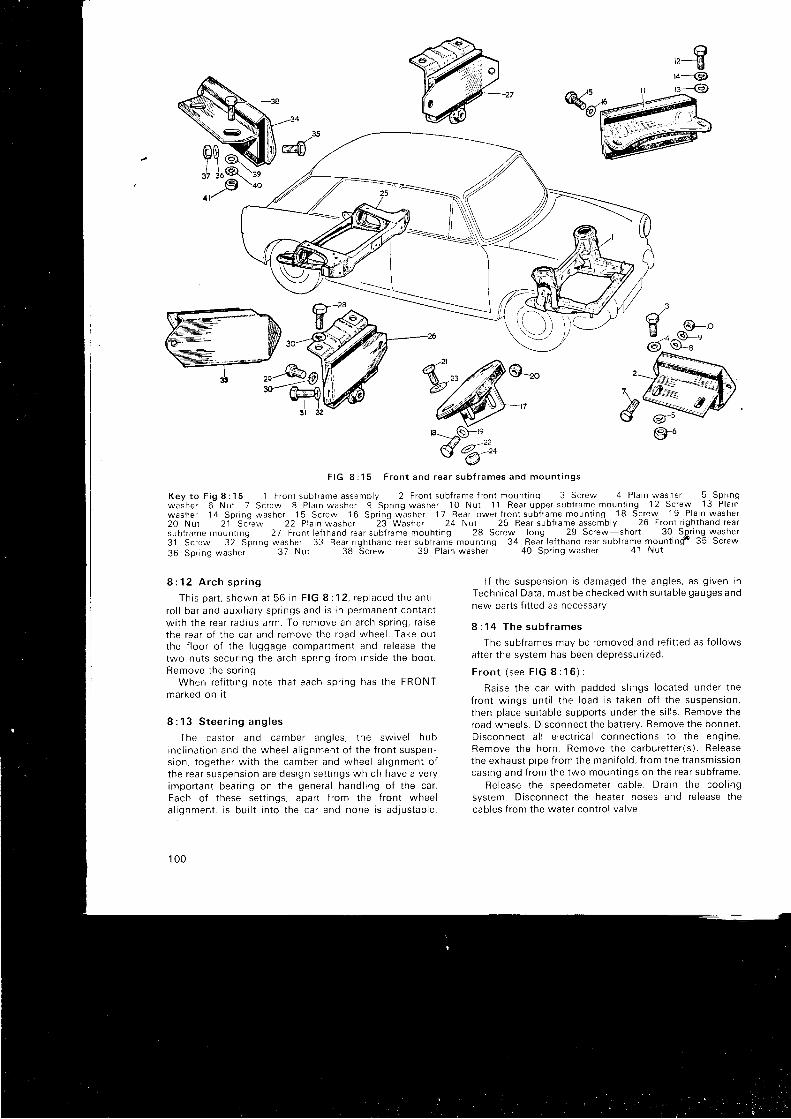
'r€'r-@
*ff-v4u{u
%k=ffi,,
F I G 8 : 1 5 F r o n t a n d r e a r s u b f r a m e s a n d m o u n t i n g s
K e y t o F i g 8 : 1 5 ' l
F r o n t s u b f r a m e a s s e m b l y 2 F r o n t s u b f r a m e f r o n t m o u n t i n q 3 S c r e w 4 P l a i n w a s h e r 5 S p r i n gw a s h e r O N u t 7 S c r e w 8 P l a r n w a s h e r 9 S p r i n g w a s h e r 1 O N u t 1 1 R e a r u p p e r s u b t r a m e m o u n t r n g 1 2 S c r e w 1 3 P l a i nw a s h e r
' l 4 S p r i n g w a s h e r 1 5 S c r e w 1 6 S p r i n g w a s h e r 1 7 R e a r l o w e r f r o n t s u b f r a m e m o u n l i n g 1 8 S c r e w 1 9 P l a i n w a s h e r2 0 N u t 2 1 S c i e w 2 2 P l a i n w a s h e r 2 3 W a s h e r 2 4 N u t 2 5 B e a r s u b f r a m e a s s e m b l y 2 0 F r o n l r i g h l h a n d r e a rsub{ rame mount ing 27 Fron t le f thand rear subf rame mouht ing 28 Screw long 29 Screw shor t 30 Sgr ing w,asher3 1 S c r e w 3 2 S l r i n g w a s h e r 3 3 R e a r r i g h t h a n d r e a r s u b f r a m e m o u n t i n g 3 4 R e a r l e f t h a n d r e a r s u b f r a m e m o u n t i n g f 3 5 S c r e w
3 6 S p r i n g w a s h e r 3 7 N u t 3 8 S c r e w 3 9 P l a i n w a s h e r 4 0 S p r i n g w a s h e r 4 1 N u t
8 : 1 2 A r c h s p r i n g
T h i s p a r t , s h o w n a t 5 6 i n F I G 8 : 1 2 , r e p l a c e d t h e a n t ir o l l ba r and aux i l i a r y sp r i ngs and i s i n pe rmanen t con tac tw i t h t he rea r r ad ius a rm . To remove an a r ch sp r i ng , r a i sethe rea r o f t he ca r and remove t he road whee l . Take ou tt he f l oo r o f t he l uggage compar tmen t and re l ease t hetwo nu t s secu r i ng t he a r ch sp r i ng f r om i ns i de t he boo t .Remove t he sp r i ng .
When re f i t t i ng no te t ha t each sp r i ng has t he FRONTmarked on i t .
8 : 1 3 S t e e r i n g a n g l e s
The cas to r and camber ang les , t he sw i ve l hubinc l i na t i on and t he whee l a l i gnmen t o f t he f r on t suspen -s i on , t oge the r w i t h t he camber and whee l a l i gnmen t o ft he rea r suspens ron a re des ign se t t i ngs wh i ch have a ve ryimpo r tan t bea r i ng on t he gene ra l hand l i ng o f t he ca r .Each of these set t ings, apart f rom the f ront wheela l i gnmen t . i s bua l t i n t o t he ca r and none i s ad jus tab le .
1 0 0
l f t he suspens ion i s damaged t he ang les , as g i ven i nTechn i ca l Da ta , mus t be checked w i t h su i t ab le gauges andnew parts f i t ted as necessary.
8 : 1 4 T h e s u b f r a m e s
The subframes may be removed and ref i t ted as fo l lowsafter the system has been depressur ized.
F r o n t ( s e e F I G 8 : 1 6 ) :
Ra i se t he ca r w i t h padded s l i ngs I oca ted unde r t hef ron t w ings un t i l t he l oad i s t aken o f f t he suspens ion ,t hen p l ace su i t ab le suppo r t s unde r t he s i l l s . Remove t heroad wheels. Disconnect the bat tery. Remove the bonnet.D i sconnec t a l l e l ec t r i ca l connec t i ons t o t he eng ine .Remove t he ho rn . Remove t he ca rbu re t t e r ( s ) . Re leasethe exhaus t o i pe f r om the man i f o l d , f r om the t r ansm iss i oncas ing and f r om the two moun t i ngs on t he rea r sub f rame .
Re lease t he speedome te r cab le . D ra i n t he :oo l i ngsystem. Disconnect the heater hoses and re lease thecab les f r om the wa te r con t ro l va l ve .
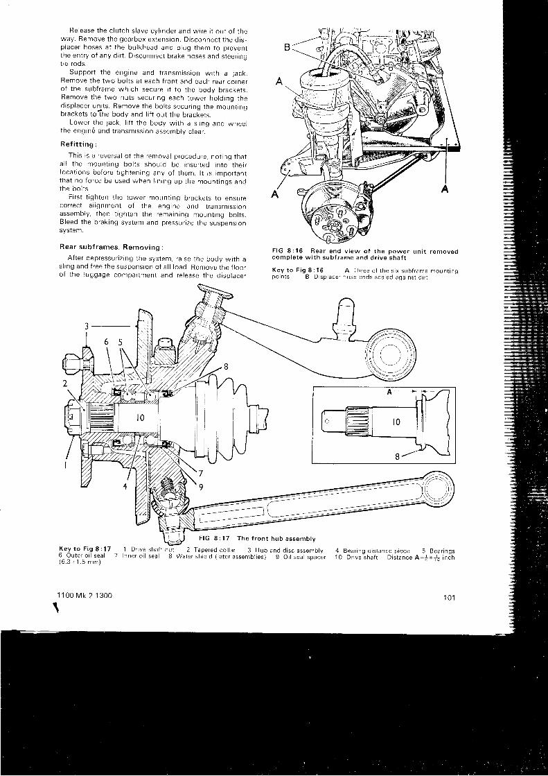
Re lease t he c l u t ch s l ave cy l i nde r and w i re i t ou t o f t heway . Remove t he gea rbox ex tens ion . D i sconnec t t he o r sp lace r hoses a t t he bu l khead and p l ug t hem to p reven tt he en t r y o f any d i r t . D i sconnec t b rake hoses and s tee r i nqlre roos.
Suppo r t t he eng ine and t r ansm iss i on w i t h a j ack .Remove t he two bo l t s a t each f r on t and each rea r co rne ro f t he sub f rame wh i ch secu re i t t o t he body b racke t s .Remove t he two nu t s secu r i ng each t owe r ho ld i ng t hed i sp lace r un i t s . Remove t he bo l t s secu r i ng t he moun t rngbrackets to.?he body and l i f t out the bracl iets.
Lower t he j ack , l i f t t he body w i t h a s l i ng and whee lt he eng ind and t r ansm iss i on assemb lv c l ea r .
R e f i t t i n g :
Th i s i s a r eve rsa l o f t he remova l p rocedu re , no t i ng t ha ta l l t he moun t i ng bo l t s shou ld be i nse r t ed i n t o t he i rl oca t i ons be fo re t i gh ten ing any o f t hem. l t i s impo r tan tt ha t no f o r ce be used when l i n i ng up t he moun t i ngs andthe bo l t s .
F i r s t t i gh ten t he t owe r moun t i ng b racke t s t o ensu reco r rec t a l i gnmen t o f t he eng ine and t r ansm iss tonassemb ly , t hen t i gh ten t he rema in i ng moun t i ng bo l t s .B leed t he b rak i ng sys tem and p ressu r i ze t he suspens ionsystem.
R e a r s u b f r a m e s . R e m o v i n g :
A f t e r dep ressu r i z i ng t he sys tem. r a i se t he body w i t h as l i ng and f r ee t he suspens ion o f a l l l oad . Remove t he f l oo ro f t he l uggage compar tmen t and re l ease t he d i so l ace r
3-_-
6 5
F I G 8 : 1 6 R e a r e n d v i e w o f t h e p o w e r u n i t r e m o v e dc o m p l e t e w i t h s u b f r a m e a n d d r i v e s h a f t
K e y t o F i g 8 : 1 6 A T h r e e o f t h e s i x s u b f r a m e m o u n t r n qp o i n t s B D i s p l a c e r h o s e e n d s s e a l e d a g a i n s t d i r t
F I G 8 : 1 7 T h e f r o n t h u b a s s e m b l v
K e y t o F i g 8 : 1 7 1 D f r v e s h a f l n u l6 O u t e r o i l s e a l 7 I n n e r o i l s e a l 8( 6 . 3 + 1 . 5 m m )
1 1 0 0 M k 2 1 3 0 0
tI
2 T a p e r e d c o l l a r 3 H u b a n d d i s c a s s e m b l vW a t e r s h i e r d t l a t e r a s s e m b l i e s ) 9 O i l s e a l s p a c e r
4 B e a r i n g d i s t a n c e p i e c e 5 B e a r i n g s1 0 D r i v e s h a f t D i s t a n c e A = : + + i n c h
1 0 1
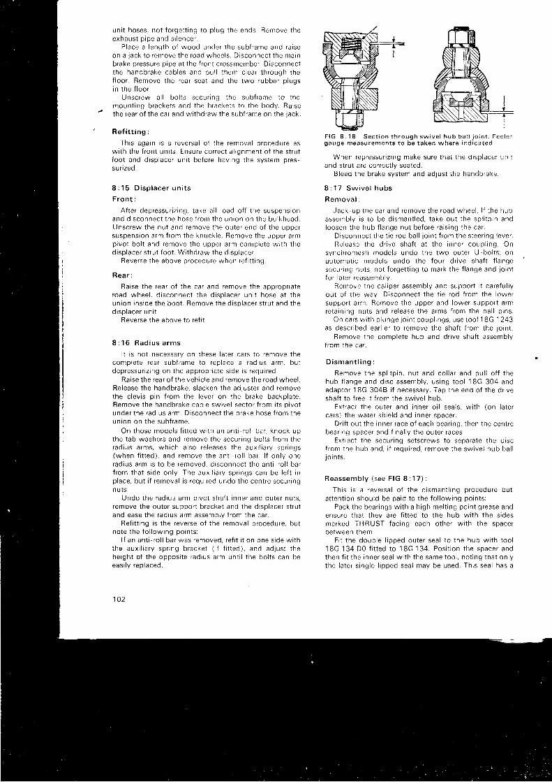
un i t hoses , no t f o rge t t i ng t o p l ug t he ends . Remove t heexhaus t p i pe and s i l ence r .
P lace a l eng th o f wood unde r t he sub f rame and ra i seon a j ack t o r emove t he road whee l s . D i sconnec t t he ma inbrake pressure pipe at the f ront crossmember. Disconnectt he handb rake cab les and pu l l t hem c l ea r t h rough t hef l oo r . Remove t he rea r sea t and t he two rubbe r p l ugsin t he f l oo r .
Unsc rew a l l bo l t s secu r i ng t he sub f rame to t hemoun t i ng b racke t s and t he b racke t s t o t he body . Ra i sethe rea r o f t he ca r and w i t hd raw the sub f rame on t he j ack .
R e f i t t i n g :
Th i s aga in i s a r eve rsa l o f t he remova l p rocedu re asw i t h t he f r on t un i t s . Ensu re co r rec t a l i gnmen t o f t he s t r u tf oo t and d i sp l ace r un i t be fo re hav ing t he sys tem p res -su r i zed .
8 : 1 5 D i s p l a c e r u n i t s
F r o n t :
A f t e r dep ressu r i z i ng . t ake a i l l oad o f f t he suspens ionand d i sconnec t t he hose t r om the un ron on t he bu l khead .Unsc rew the nu t and remove t he ou te r end o f t he uppe rsuspens ion a rm f r om the knuck le . Remove t he uppe r a rmp i vo t bo l t and remove t he uppe r a rm con tp i e te w i t h t hed i sp lace r s t r u t f oo t . W i t hd raw the d i sp l ace r .
Reverse the above procedure when ref i t t ing.
R e a r :
Ra i se t he rea r o f t he ca r and remove t he app rop r i a teroad whee l , d i s connec t t he d i sp l ace r un i t hose a t t heun ion i ns i de t he boo t . Remove t he d i sp l ace r s t r u t and t hed i sp lace r un i t .
Reverse the above to ref i t .
8 : 1 6 R a d i u s a r m s
I t i s no t necessa ry on t hese l a t e r ca r s t o r emove t hecomp le te r ea r sub f rame to r ep lace a r ad ius a rm , bu tdep ressu r i z i ng on t he app rop r i a te s i de i s r equ i r ed .
Raise the rear of the vehic le and remove the road wheel .Release the handbrake, s lacken the adjuster and removethe c l ev i s p i n f r om the l eve r on t he b rake backp la te .Remove t he handb rake cab le sw i ve l sec to r { r om i t s p i vo tunde r t he rad ius a rm . D i sconnec t t he b rake hose f r om theun ion on t he sub f r ame .
On t hose mode l s f i t t ed w i t h an an t i - r o l l ba r , knock upthe t ab washe rs and remove t he secu r i ng bo l t s f r om therad ius a rms , wh i ch a l so re l eases t he aux i l i a r y sp r i ngs(when f i t t ed ) , and remove t he an t i - r o l l ba r . l f on l y onerad rus a rm i s t o be removed , d i sconnec t t he an t i - r o l l ba rf r om tha t s i de on l y . The aux i l i a r y sp r i ngs can be l e f t i np l ace . bu t r f r emova l i s r equ i r ed undo t he cen t re secu r i ngn uts.
Undo t he rad ius a rm p i vo t sha f t i nne r and ou te r nu t s ,remove the outer support bracket and the displacer st rutand ease t he rad ius a rm assemb ly f r om the ca r .
Ref i t t ing is the reverse oi the removal procedure, butno te t he f o l l ow ing po in t s :
l f an an t i - r o l l ba r was removed , r e { i t i t on one s i de w i t hthe aux i l i a r y sp r i ng b racke t ( i f f i t t ed ) , and ad jus t t hehe igh t o f t he oppos i t e r ad ius a rm un t i l t he bo l t s can beeas i l y r ep laced .
102
F I G 8 : 1 8 S e c t i o n t h r o u g h s w i v e l h u b b a i , j o i n tgauge measu remen ts t o be t aken whe re i n€ l i ca ted
When rep ressu r i z i ng make su re t ha t t he d i sp i dce r r I n i land strut are correct ly seated.
B leed t he b rake sys tem and ad jus t t he handb rake .
8 : 1 7 S w i v e l h u b s
R e m o v a l :
Jack -up t he ca r and remove t he road whee l . l f t he hubassemb ly r s t o be d i sman t l ed , t ake ou t t he sp l i t p i n andloosen t he hub f l ange nu t be fo re r a i s i ng t he ca r .
D i sconnec t t he t i e r od ba l l j o i n t f r om the s tee r i ng l eve r .Re lease t he d r i ve sha f t a t t he i nne r coup l i ng . On
synch romesh mode l s undo t he two ou te r U -bo l t s ; onau toma t i c mode l s undo t he f ou r d r r ve sha f t f l angesecu r i ng nu t s , no t f o rge t t i ng t o ma rk t he f l ange and j o i n tf o r l a t e r r eassemb ly .
Remove t he ca l i pe r assemb ly and suppo r t i t ca re fu l l you t o { t he way . D i sconnec t t he t i e r od f r om the l owe rsuppo r t a rn r . Remove t he uppe r and l owe r suppo r t a rmre ta i n i ng nu t s and re l ease t he a rms f r om the ba l l p rns .
On ca rs w i t h p l unge l o i n t coup l i ngs , use t oo l 18G 1 243as desc r i bed ea r l i e r t o r emove t he sha f t f r om the j o i n t .
Remove t he comp le te hub and d r r ve sha f t assemb lyf r om the ca r .
D i s m a n t l i n g :
Remove t he sp l i t p i n , nu t and co l l a r and pu l l o f f t hehub f l ange and d i sc assemb ly , usang t oo l 18G 304 andadap to r 1 BG 3048 i f necessa ry . Tap t he end o f t he d r i veshaft to { ree i t f rom the swivel hub.
Ex t rac t t he ou ie r and rnne r o i l sea l s ,ca r s ) t he wa te r s l i i e l d and i nne r space r .
D r i f t ou t t he i nne r r ace o f each bea r i ng ,bea r i ng space r and f i na l l y t he ou te r r aces
w i t h ( on l a t e r
t hen t he cen t re
Extract the secur ing setscrews to separate the discf r om the hub and , i f r equ i r ed , r emove t he sw i ve l hub ba l lJOr n t s .
R e a s s e m b l y ( s e e F I G I : 1 7 ) :
Th i s i s a r eve rsa l o f t he d i sman t l i ng p rocedu re bu ta l t en t i on shou ld be pa id t o t he f o l l ow ing po in t s :
Pack t he bea r i ngs w i t h a h i gh me l t i ng po in t g rease andensure that they are f i t ted io the hub wi th the s idesmarked TH R UST fac i ng each o the r w i t h t he space rbe tween t hem.
F i t t he doub le l i pped ou te r sea l t o t he hub w i t h t oo l18G 134 D0 t i ned t o 18G 134 . Pos i t i on t he space r andthen f i t t he i nne r sea l w i t h t he same too l , no t i ng t ha t on l yt he l a t e r s i ng le l i pped sea l may be used . Th i s sea l has a
I- {-T-
I
r eg i s t e r f o r t he wa te r sh i e l d wh i ch i s f i t t ed as shown i ntne I nse t .
On ca rs w i t h p l unge j o i n t s , engage t he d r j ve sha f t asdesc r i bed i n Sec t i on 8 : 7 .
Lgh ten t he ba l l p i n r e ta i n i ng nu t s t o a t o rque o f 35 t o40 l b f t . No te t ha t i f t he ba l l j o i n t s have been removedthey mus t be ad lus ted as desc r i bed l a t e r i n t h i s Sec t i on .
On synch romesh t r ansm iss i ons w i t h f l e x i b l e d r i vecoup l i ngs , t i gh ten t he U bo l t s as desc r i bed ea r l i e r . Onau toma t i c l r ansm iss i ons a l i gn t he { l ange marks be fo ref i n i ng and l i gh ten ing t he secu r i ng bo l t s .
T i gh ten t he d r i ve sha f t nu t t o 1b0 l b f t and check t herunou t a f t he ou te r pe r i phe ry o f t he d i sc . Th i s shou ld no tb e m o r e t h a n . 0 0 6 i n c h ( . 1 5 m m ) .
B a l l j o i n t s :
These may be removed af ter d isconnect ing the 1ie rodf rom the l owe r suppo r t a rm . Remove t he uppe r suppo r ta rm re ta rn i ng nu t and re l ease t he ba l l p i n ( 1 BG 1 063 ) .
Remove t he dus t cove r and l ub r i ca to r , knock up t helockwashe r and unsc rew the hous ing us i ng t oo l 1 gG Sg7f i t ted to a T bar, tak ing care that the dr ive shaf t is nots t r a i ned . Ex t rac t t he ba l l sea t and t he pack ing sh ims .
Remove t he l owe r ba l l l o i n t and sea t sp r i ng , p re fe rao rya f t e r t he uppe r l o i n t has been ad ius ted and re f i t t ed .
Ad jus t i ng t he ba l t j o i n t s :
F i r s t c l ean and exam ine a l l t he componen ts t hen re f t tt he ba l l sea t p i n and hous ing w i t hou t any sh ims , l oc rwashe r o r sea t sp r i ng ( l owe r j o i n t ) . Sc rew down t heba l l hous ing un t i l a l l s l ack r s j us t e l im ina ted .
Measu re t he gap be tween t he hous ing and t he swrve lh u b a s s h o w n i n F I G 8 : 1 8 a n d t h e n r e m o v e t h e h o u s r r r oa n d b a l l p i n .
Re f i t t he sp r i ng unde r t he l owe r l o i n t ba l l sea t andpack t he assemb ly w i t h g rease . Sc rew the hous ing backon t o t he sw i ve l hub w i t h i t s l ockwashe r . wh i ch i s . 036inch ( . 9 mm) t h i ck , and su f f i c i en t sh ims t o make a t o ta lt h i c kness o f 0 t o . 003 i nch g rea te r t han t he measu remenrj us t t aken t o p roduce t he necessa ry end f l oa t . Any unduetrghtness or excessive f loat must be rect i f ied by adlust ingthe sh im t h i ckness .
The assemb ly mus t r o ta te and a r t i cu l a te f r ee l y i n a t tp l anes . l f t h i s f r eedom i s no t ob ta tned , new pa r t s mus t bef i t red.
R e f i t t i n g :
T igh ten t he ba l l hous ing t o 70 l b f t , t hen re f i t t nel ub r i ca to r be fo re secu r i ng t he l ockwashe r .
Re f i t t he uppe r and l owe r dus t cove rs and t he ba r rp i ns and t r gh ten t he secu r i ng nu t s t o 35 t o 40 l b f t . Re f i tt he t i e r od and t he whee l and l owe r t he ca r on to t he road .
1 1 0 0 M k 2 1 3 0 0
8 : 1 8 A n t i - r o l l b a r a n d a u x i l i a r y s p r i n g s
E i t he r o r bo th o f t hese componen ts may be f i t t ed t oany pa r t t cu l a r ca r and no d i f f i cu l t y w i l l be expe r i enced i ntheir removal af ter the H),drolast ic system has beendep ressu r i zed and t he rea r end o f t he ca r l i f t ed .
The an t i - r o l l ba r i s r emoved f i r s t and t hen t he aux i l i a r ysp r i ngs may be removed .
Re f i t t i ng i s a l so s t r a i gh t f o rwa rd , no t i ng t ha t t he an t i -r o l l ba r shou ld be f i r s t secu red on one s i de w i t h t heaux r l t a r y sp r i ng b racke t (whe re app l i cab le ) and t he he rgn ro f t he oppos i t e r ad ius a rm ad jus ted un t j l t he bo l t s canbe eas i l y i nse r t ed .
Ad jus tmen t :
The nom ina l gap be tween t t r 6 . . 1 ; ' , , 1 , , i , ! . acke t and t heunde rs i de o f t he sub - f r ame i s . 1 i nc i r ( . j . 2 i n ; - n ) , bu t i f j t i sr equ i r ed t o make a sma l i ad l r t s t r nen l t o t he t r im he igh tt h r s can be va r i ed be tween 0 and i i n ch (6 .4 mm) .
S lacken t he cen t re secu r i ng nu t s o f t he aux r l i a r ysp r i ngs and re l ease t he l ocknu t s on t he ad jus te r sc rews .These a re unsc rewed t o r educe t he gap i t an i nc rease o ft r im he igh t i s r equ i r ed , o r sc rewed up t o r educe t heheight . l t may be necessary to load the car to reducesp r i ng t ens ion du r i ng t h i s l a t t e r ope ra t i on .
8 : 1 9 F a u l t d i a g n o s i s
(a ) Whee l wobb le
1 I nco r rec t t r ack rng2 Worn hub bea r i ngs3 De fec t i ve suspens ion un r t s4 Worn sw i ve l hub j o i n t s5 Loose whee l { i x i ngs
(b ) 'Bo t t om ing ' o f suspens ion
1 C h e c k 3 i n ( a )2 I nco r rec t p ressu r i z i ng3 Rebound rubbe rs wo rn o r m i ss i ng
(c ) Heavy s tee r i ng
1 Neg lec ted sw i ve l hub l ub r i ca t i on2 Wrong suspens ion geome t r y
(d ) Excess i ve t y re wea r
1 C h e c k 1 i n ( a ) a n d 2 i n ( c )
( e ) Ra t t l es
1 C h e c k 1 i n ( c )2 Rad ius a rm moun t i ngs de fec t i ve
( f ) Excess i ve ro l l i ng
1 C h e c k 3 i n ( a ) a n d 2 i n ( b )2 An t i r o l l ba r b roken o r f i x i ngs l oose
1 0 3
CHAP'TER 9
T H E S T E E R I N G G E A R
9 : 1 Desc r i p t i on9 : 2 L u b r i c a t i o n9 :3 The s tee r i ng whee l9 :4 The s tee r i ng co lumn9 : 5 S t e e r i n g r a c k a n d p i n i o n
9 : 1 D e s c r i p t i o n
The components of the rack and pin ion type steer inggea r a re i l l u s t r a ted i n F IG 9 :1 . The rack hous ing 1 i ssecured to the engine bulkhead, the t ie rods 23 operat ingthe steer ing arms are at tached to each end of the steer ingrack 5 by bal l jo ints 31 enclosed in rubber gai ters. Thesteer ing column 43 engages the spl ined end of a hel icalt oo thed p i n i on 13 t o wh i ch i t i s secu red bv a c l amp bo l tand wh i ch engages t he rack .
P in i on end p l ay i s e l im ina ted by t he ad jus rmen t o f t hesh ims 19 f i t t ed unde r t he re ta i n i ng p l a te 18 . A damper pad6 under the steer ing rack contro ls the backlash betweenthe pin ion and the rack.
l f the f ront wheels are l i f ted c lear of the ground durrngservic ing operat ions, i t is important that they should notbe moved forceful ly f rom lock to lock as damage may becaused to the s leer ing mechanism.
9 : 2 Lub r i ca t i on
No p rov i s i on i s made f o r pe r i od rc l ubnca t t on o t t nes tee r i ng rack , and rep len i shmen t i s r equ i r ed on l y whenthere is evidence of o i l loss f rom the rack housing or therubber gai ters. No lubr icat ing nipples are provided and i fthe leakage can be rect i f red wi thout the rack assembly 'being removed, the fo l lowing procedure should oeadopted:
Remove the reta in ing c l ip 29 f rom the gai ter at ther i gh thand end o f t he rack hous ing (o r l e f t hand end on
1 1 0 0 M k 2 1 3 0 0
9 : 6 T r a c k i n g9 : 7 O u t e r b a l l j o i n t s9 :8 S tee r i ng l ock and i gn i t i on sw i t ch9 : 9 F a u l t d i a g n o s i s
l e f t hand d r i ve ca rs ) and pu l l t he ga i t e r f r om the hous ing .Move the rack to the stra ight-ahead posi t ion and insertan o i l nozz le i n t o t he end o f t he rack hous ing and i n l ec tnot more than * p int of Extreme Pressure SAE.90 oi l .Replace the rubber gai ter and move the rack f rom side tos i de t o d i s t r i bu te t he o i l t h roughou t t he hous ing .
9 : 3 The s tee r i ng whee l
Aus t i n Amer i ca and GT .
Disconnect the bat tery and lever out the centra l safetyboss, remove the steer ing wheel nut . Turn back the lockr ing tabs and remove the bol ts, lock r ing and steer ingwhee l .
l f t he hub i s t o be removed , use t oo l 18G 1181 andpul l i t of f complete wi th the steer ing wheel , not forget t ingto ma rk t he hub and co lumn fo r r e f i t t i nq .
A l l o t he r mode l s :
Lever out e i ther the horn push contro l , centre mot i f orsafety pad, as appl icable.
Slacken, but do not remove, the reta in ing nut and pul lt he s tee r i ng whee l w i t h t oo l 18G 70 un t i l i t i s a l oose f i ton t he co lumn . Remove t he pu l l e r , nu t and whee l .
When ref i t t ing, make sure that the road wheels are inthe stra ight ahead posi t ion and the spokes on the steer ingwheel centra l . The correct torque for the reta in ing nut is32 to 37 lb f t .
1 0 5
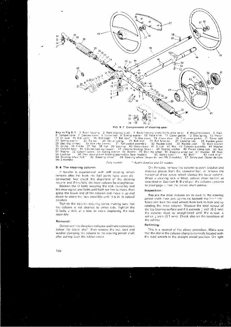
?4 f,\
::€q37
, ',., ,,
t lt 0 4
/ ' ' 1 7^ / ' ' a a
t-Wi,-21 zt,/,c z I/'/,4\ 3\lJ 4l
38 _ .€ (y_ 37
F I G 9 : 1 C o n t p o n e n t s o f s t e e r i n g g e a r
K e y t o F i g 9 : l l R a c k h o u s r n g 2 R a c k h o u s i n g b u s h 3 B u s h h o u s r n g ( e a r l y f e l t b u s h e s o n l y ) 4 H o u s i n g s c r e w s 5 R a c l .6 D a m p e r y o k e 7 D a m p e r c o v e r 8 C o v e r b o l t 9 S p r i n g w a s h e r ' 1 0 Y o k e s h i m 1 1 C o v e r g a s k e t 1 2 D i s c s p r i n g 1 3 P i n i o n1 4 O i l s e a l 1 5 B a l l c o n e l 6 B a l l c a g e ' 1 7 B a l l c u p ' 1 8 E n d c o v e r 1 9 C o v e r s h i m 2 0 E n d c o v e r g a s k e t 2 1 C o v e r b o l t2 2 S p r r n g w a s h e r 2 3 T i e r o d 2 4 T h r u s t s p r i n g 2 5 B a l l s e a t 2 6 B a l l h o u s i n g 2 7 L o c k i n g r i n g 2 8 R u b b e r g a i t e r2 9 S e a l c l i p ( n n e r ) 3 0 S e a l c l i p ( o u t e r ) 3 ' 1 B a l l s o c k e t a s s e m b l y 3 2 R u b b e r b o o t 3 3 R u b b e r b o o t 3 4 B o o t w a s h e r3 5 C i r c l i p 3 6 C r r c l i p 3 7 N u t 3 8 N u t 3 9 L o c k n u t 4 0 C l a m p b a s e 4 1 U - b o l l 4 2 N u t 4 3 C o l u m n a s s e m b l y 4 4 W a s h e r4 5 C o l u m n t u b e 4 6 C o l u m n b e a r i n g ( u p p e r ) 4 7 C o l u m n b e a r i n g ( l o w e r ) 4 8 S e a l i n g w a s h e r 4 9 P i n i o n c l a m p b o l t 5 0 N u t5 1 W a s h e r 5 2 C o l u n r n s c r e w 5 3 S p r i n g w a s h e r 5 4 W a s h e r 5 5 S t e e r i n g w h e e l 5 6 S t e e r i n g w h e e l n u t 5 7 W a s h e r 5 8 S t u d5 9 L o c k n u t 6 0 O n e p r e c e p i n r o n b e a r i n g a s s e m b l i e s ( l a t e r m o d e l s ) 6 1 S a f e t y b o s s i ' . 6 2 B o l t - ' 6 3 L o c k r i n g t -6 4 S t e e r i n g w h e e l h u b * - 6 5 S t e e r r n q i r y h e e l " " 6 6 S t e e r i n g w h e e l ( S u p e r d e - l u x e M k 3 m o d e l s ) 6 7 S a f e t y p a d ( S u p e r d e - l u x eM k 3 m o d e l s )
" Austin America and GT models
l 9/ 3 0
45 t \ '50
e 6 .
64
'Early ntodels
9 : 4 T h e s t e e r i n g c o l u m n
l f t r oub le i s expe r i enced w i t h s t i f f s t ee r i ng wh i chrema ins a f t e r t he t r ack r od ba l l j o i n t s have been d i s -connec ted , f i r s t check t he a l i gnmen t o f t he s tee i l ngco lumn and i f t h i s f a i l s , t he rnne r co l umn fo r s t r a rgh tness .
S lacken t he L l - bo l t s secu r i ng t he rack assemb ly andthe s tee r i ng co lumn bo l t s un t i l bo th a re f r ee t o move , t heng rasp t he l owe r end o f t he co lumn and move i t up anddown t o r o ta te t he rack assemb ly un t i l i t i s i n i t s na tu ra lpos r ron
T igh ten t he co lumn secu r i ng sc rew mak ing su re t ha tt he co lumn i s no t s t r a i ned t o e i t he r s i de . T i gh ten t heU-bo l t s a l i t t l e a t a t ime t o avo id d i sp l ac i ng t he rackassemDry .
R e m o v a l :
D i sconnec t t he d i r ec t i on i nd i ca to r and ho rn connec to r sbe low t he pa f ce l she l f . t hen remove t he nu t , bo l t andwashe r c l amprng t he co lumn to t he s tee r i ng p i n i on sha f ta f t e r pu l l i ng back t he rubbe r cove r .
1 0 6
On P r i ncess , r emove t he co lumn suppo r t b racke t andd i s tance p i eces f r om the c rossmember , o r r emove t hef ro r i zon ta l shea r sc rew wh i ch c l amps t he ou te r co l umn .When a s tee r i ng l ock i s f i t t ed , ex t r ac t shee r bo l t ( s ) asd e s c r i b e d r n S e c ; i o n 9 : 8 a n d p u l l t h e c o l u m n u p w a r d sto d i sengage i t f r o r r t he p i n i on sha f t sp l i nes .
I n s p e c t i o n :
Rep lace t he i nne r co l umn on i t s own t o t he s tee r i ngp in i on sha f t , t hen j ack up t he ca r benea th { hg J ! . n , ' + c ' r b -
f r ame and t u rn t he road whee l s f r om l ock t o l ock and soro ta t i ng t he i nne r co l umn . Measu re t he t o ta l r unou t o ft he t op bea r i ng su r f ace and i f i t e xceeds j i n ch (6 .2 mm)the co lumn mus t be s t r a i gh tened un t i l t he r unou t i sw i t h i n + i nch (3 .1 mm) . Check a l so on t he cond i t i on o ft he sp l r nes .
R e f i t t i n g :
Thjs is a reversal of the above procedure. Make suretha t t he s l o t i n t he co lumn c l amp i s co r rec t l y l oca ted w i t hthe road whee l s i n t he s t r a i gh t ahead pos i t i on . On r i gh t
. 5453
4947
\ '>-\)i \
?(-^ \7|34,,-g t$l', "'
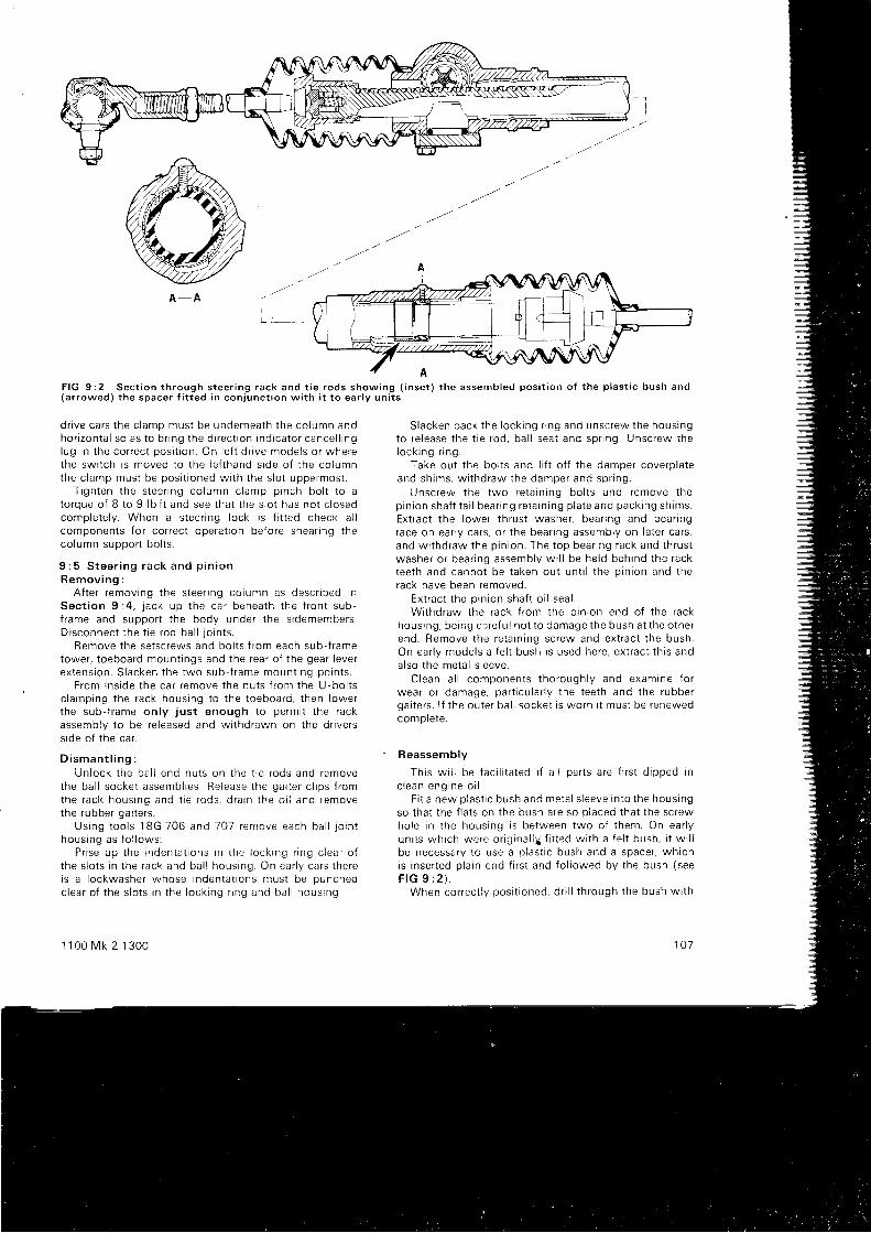
A - A
F I G 9 : 2 S e c t i o n t h r o u g h s t e e r i n g r a c k a n d t i e r o d s s h o w i n g ( i n s e t ) t h e a s s e m b l e d p o s i t i o n o f t h e p l a s t i c b u s h a n d( a r r o w e d ) t h e s p a c e r f i t t e d i n c o n j u n c t i o n w i t h i t t o e a r l y u n i t s
d r i ve ca rs t he c l amp mus t be unde rnea th t he co lumn andho r i zon ta l so as t o b r i ng t he d i r ec t i on i nd i ca to r cance l l i ngl ug i n t he co r rec t pos i t i on . On l e f t d r i ve mode l s o r whe rethe sw i t ch i s moved t o t he l e f t hand s i de o f t he co lumnthe c l amp mus t be pos i t i oned w i t h t he s l o t uppe rmos t .
T i gh ten t he s tee r i ng co lumn c l amp p inch bo l t t o ato rque o f B t o 9 l b f t and see t ha t t he s l o t has no t c l osedcomp le te l y . When a s tee r i ng l ock i s f i t t ed check a l lcomponents for correct operat ion before shear ing theco lumn suDoo r t bo l t s .
9 : 5 S t e e r i n g r a c k a n d p i n i o nB e m o v i n g :
A f t e r r emov ing t he s tee r i ng co lumn as desc r i bed i nSec t i on 9 :4 , j ack up t he ca r benea th t he f r on t sub -f r ame and suppo r t t he body unde r t he s i demembers .D i sconnec t t he t i e r od ba l l j o i n t s .
Remove t he se t sc rews and bo l t s f r om each sub - f r ametower, toeboard mount ings and the rear of the gear leverex tens ion . S lacken t he two sub f r ame moun t i ng po in t s .
F rom i ns i de t he ca r r emove t he nu t s f r om the U -bo l t sc l a rnp ing t he rack hous ing t o t he t oeboa rd , t hen l owe rthe sub - f r ame on l y j us t enough t o pe rm i t t he rackassemb ly t o be re l eased and w i t hd rawn on t he d r i ve r ss i de o f t he ca r .
D i s m a n t l i n g :Un lock t he ba l l end nu t s on t he t i e r ods and remove
the ba l l socke t assemb l i es . Re iease t he ga i t e r c l i p s f r omthe rack hous ing and t i e r ods , d ra i n t he o i l and removethe rubbe r ga i t e r s .
Us ing t oo l s 1BG 706 and l 0 -7 r en rove each ba l l j o rn thous ing as f o l l ows :
P r i se up t he i nden ta t i ons i n t he l ock i ng r i ng c l ea f o ft he s l o t s i n t he rack and ba l l hous ing . On ea r l y ca r s t he rei s a l ockwashe r whose i nden ta t i ons mus t be punchedc lea r o f t he s l o t s i n t he l ock i ng r i ng and ba l i hous ing
1 1 0 0 M k 2 1 3 0 0
S lacken back t he l ock i ng r i ng and unsc rew the hous ingto r e l ease t he t r e r od , ba l l sea t and sp r i ng . Unsc rew thelock i ng r i ng .
Take out the bol ts and l i f t of f the damper coverplateand sh ims , w i t hd raw the damper and sp r i ng .
Unsc rew the two re ta i n i ng bo l t s and remove t hep in i on sha f t t a i l bea r i ng re ta i n i ng p l a te and pack ing sh ims .Ex t rac t t he l owe r t h rus t washe r , bea r i ng and bea r i ngrace on ear ly cars, or the bear ing assembly on later cars,and w i t hd raw the p i n i on . The t op bea r i ng rack and t h rus twashe r o r bea r i ng assemb ly w i l l be he ld beh ind t he racktee th and canno t be t aken ou t un t i l t he p i n i on and t herack have been removed.
Ex t rac t t he p i n i on sha f t o i l sea l .Wr thd raw the rack f r om the p i n i on end o f t he rack
housing. beir ig c: - l ref u l not to damage the bush at the otherend . Remove t he re ta i n rng sc rew and ex t rac t t he bush .On ea r l y mode l s a f e l t bush i s used he re , ex t r ac t t h i s andalso the metal s leeve.
C lean a l l componen ts t ho rough l y and examtne f o rwea r o r damage , pa r t i cu l a r l y t he t ee th and t he rubbe rga i t e r s . l f t he ou te r ba l l socke t i s wo rn i t mus t be renewedcomplete.
Reassemb ly
Th i s w i l l be f ac i l i t a t ed i f a l l pa r t s a re f i r s t d i pped i nc l e a n e n g i n e o i l .
F i t a new p las t i c bush and me ta l s l eeve i n t o t he hous rngso t ha t t he f i a t s on t he bush a re so p l aced t ha t t he sc rewho le i n t he hous ing i s be tween two o f t hem. On ea r l yun i t s wh i ch we re o r i g i na l i y f i t t ed w i t h a f e l t bush , i t w i l lbe necessa ry t o use a p l as t i c bush and a space r , wh i chi s i nse r t ed p l a i n end f i r s t and f o l l owed by t he bush ( seeF I G 9 : 2 ) .
When co r rec t l y pos i t i oned , d r i l l t h rough t he bush w i t h
107
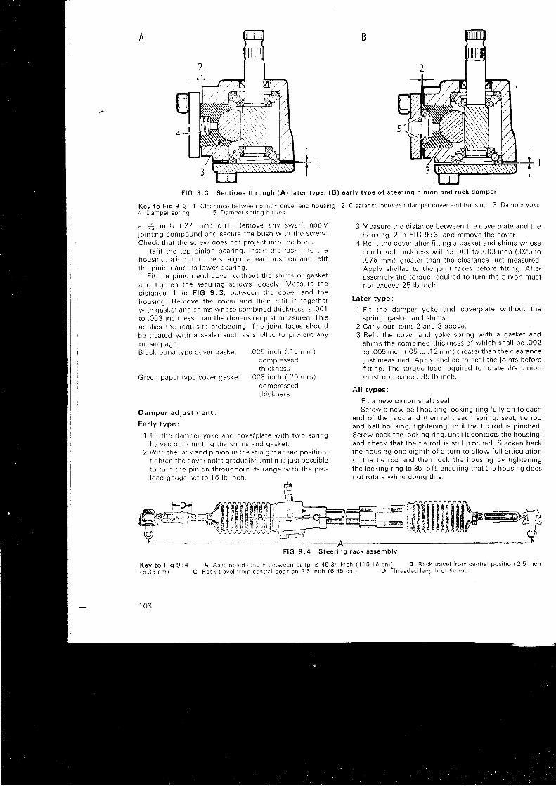
A
F I G 9 : 3 S e c t i o n s t h r o u g h ( A ) l a t e r t y p e , ( B ) e a r l y t y p e o f s t e e r i n g p i n i o n a n d r a c k d a m p e r
K e y t o F i g g : 3 l C l e a r a n c e b e t w e e n p r n r o n c o v e r a n c i h o u s i n g 2 C l e a r a n c e b e t w e e n d a m p e r c o v e r a n d h o u s i n g 3 D d n r p e r y o k e4 D a n r p e r s p r n g 5 D a m p e r s p r t n g h a i v e s
a &z i nch ( . 27 mm) d r i l l . Ren tove any swa r f , app l y
l o i n t i ng compound and secu re t he bush w i t h t he sc rew .Check t ha t t he sc rew does no t p ro l ec t i n t o t he bo re .
Re f i t t he t op p i n i on bea r i ng I nse r t t he rack i n t o t hehous ing , a l i gn i t i n t he s t r a i gh t ahead pos i t i on and re f i tt h e p r n i o n a n d r t s l o w e r b e a r i n g .
F i t t he p i n i on end cove r w i t hou t t he sh ims o r gaske t
and t i gh ten t he secu r i ng sc rews l oose l y . Measu re t he
d i s t ance , 1 r n F IG 9 :3 . be tween t he cove r and t hehous ing . Remove t he cove r and t hen re f i t i t t oge the rw i t h gaske t and sh ims whose comb ined t h i ckness i s . 001
to . 003 i nch l ess t han t he d imens ion j us t measu red . Th i sapp l i es t he requ i s i t e p re l oad ing The j o i n t t aces shou ld
be t r ea ted w i t h a sea le r such as she l l ac t o p reven t anyo r l seepage .B lack buna t ype cove r gaske t . 006 t nch ( ' 1
5 mm)com p ressedtn r cKness
Green pape r t ype cove r gaske t . 0OB i nch ( . 20 mm)com p ressedt h i c k n e s s
D a m p e r a d l u s t m e n t :
E a r l y t y p e :
1 F i t t he damper yoke and cove ip l a te w i t h two sp r i ngha l ves bu t om i t t i ng t he sh ims and gaske t .
2 Wr t l r t he r ack and p rn i on i n t he s t r a i gh t ahead pos i t i on ,t i gh ten t he cove r bo l t s g radua i l y un t i l i t i s j us t poss ib l eto t u rn t he p i n ron t h roughou t i t s f ange w i t h t he p re -l oad gauge ; e t t o 1 5 l b i nch .
F I G 9 : 4 S t e e r i n g r a c k a s s e m b l Y
A A s s e m b l e d l e n q t h b e r w e e n b a l l p r n s 4 5 . 3 4 i n c h ( 1 1 5 1 6 c m ) B R a c k t r a v e l l r o m c e n t r a l p o s i t i o n 2 . 5 i n c hR a c k t r r v e l f r o r n c e n t r a l p o s i t i o n 2 . 5 n c h ( 6 . 3 5 c m ) D T h r e a d e d l e n g t h o f t i e r o d
3 Measu re t he d i s t ance be tween t he cove rp l a te and t hehous ing , 2 i n F IG 9 :3 , and remove t he cove r .
4 Re f i t t he cove r a f t e r f i t t i ng a gaske t and sh ims whosecomb ined t h i ckness w i l l be . 001 t o . 003 i nch ( . 025 t o.076 mm) g rea te r t han t he c l ea rance j us t measu red .App l y she l l ac t o t he j o i n t f aces be fo re f i t t i ng . A f t e rassen rb l y t he t o rque requ i r ed t o t u rn t he p i n i on mus tno t exceed 25 l b i nch .
La te r t ype :
l F i t t he damper yoke and cove rp l a te w i t hou t t hesp r i ng , gaske t and sh ims .
2 Ca r r y ou t i t ems 2 and 3 above .3 Re f i t t he cove r and yoke sp r i ng w i t h a gaske t and
sh ims t he comb ined t h i ckness o f wh i ch sha l l be . 002to . 005 i nch ( . 05 t o . 12 mm) g rea te r t han t he c l ea rancejus t measu red . App l y she l l ac t o sea l t he j o i n t s be fo ref i t t i ng . The t o rque l oad requ i r ed t o r o ta te t h? p i n ton
mus t no t exceed 35 l b i nch .
A l l t y p e s :
F i t a new p in ron sha f t sea l .Sc rew a new ba l l hous ing l ock i ng r i ng f u l l y on t o each
end o f t he rack and t hen re f i t each sp r i ng , sea t , t i e r odand ba l l hous ing , t i gh ten ing un t i l t he t i e r od i s p i nched .Sc rew back t he l ock i ng r i ng , un t i l i t con tac t s t he hous ing ,and check t ha t t he t i e r od i s s t i l l p i nched . S lacken backthe hous ing one e i gh th o f a t u rn t o a l l ow f u l l a r t i cu l a t r ono f t he t i e r od and t hen l ock t he hous ing by t i gh ten ingthe l ock i ng r i ng t o 35 l b f t , ensu r rng t ha t t he hous ing doesno t r o ta te wn r l e do ' nc r t h i s .
K e y t o F i g 9 : 4( 6 . 3 5 c m ) C
1 0 8
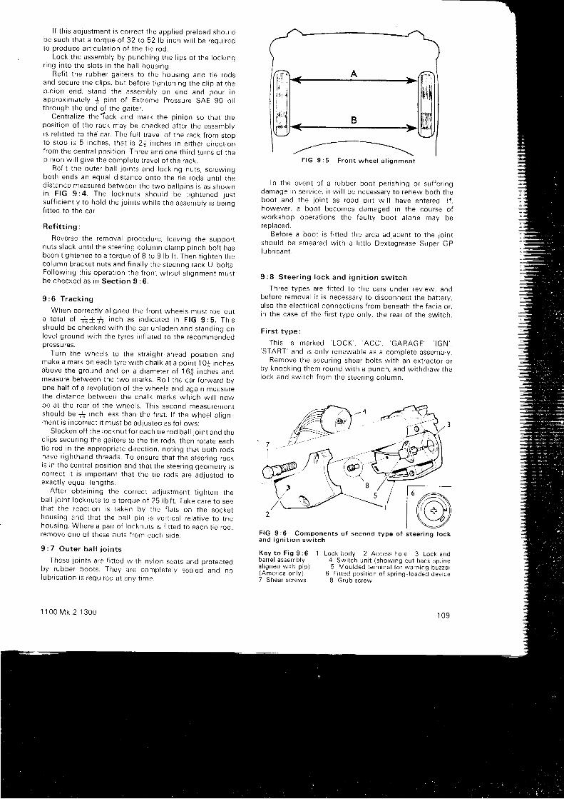
l f t h i s ad jus tmen t i s co r rec t t he app l i ed p re l oad shou robe such t ha t a t o rque o f 32 t o 52 l b i nch w i l l be r equ i r edto p roduce a r t i cu l a t i on o f t he t i e r od .
Lock t he assemb ly by punch ing t he l i p s o f t he l ock rngr i ng i n t o t he s l o t s i n t he ba l l hous ing .
Re f i t t he r ubbe r ga i t e r s t o t he hous ing and t i e r odsand secu re t he c l i ps , bu t be fo re t i gh ten ing t he c l i p a t t hep in i on end , s t and t he assemb ly on end and pou r i napp rox ima te l y { p i n t o f Ex t reme P ressu re SAE 90 o i lt h rough t he end o f t he ga r t e r .
Cen t ra l i ze t he?ack and mark t he p i n i on so t ha t t hepos i t i on o f t he rack may be checked a f t e r t he assemb lyis ref i t ted to the car. The fu l l t ravel of the rack f rom stopto s t op i s 5 i nches . t ha t i s 2+ i nches i n e i t he r d i r ec t r onf rom the cen t ra l pos i t i on . Th ree and one t h i r d t u rns o f t hep in i on w i l l g i ve t he comp le te t r ave l o f t he rack .
Re f i t t he ou te r ba l l j o i n t s and l ock i ng nu t s , s c rew ingbo th ends an equa l d i s t ance on to t he t i e r ods un t i l t hed rs tance measu red be tween t he two ba l l p i ns i s as shownin F IG 9 : 4 . The l ocknu t s shou ld be t i gh tened j us tsu f f i c i en t l y t o ho ld t he j o i n r s wh i l e t he assemb ly i s be ingf i t ted to the car.
R e f i t t i n g :
Reve rse t he remova l p rocedu re , l eav i ng t he suppo r tnu t s s l ack un t i l t he s tee r i ng co lumn c l amp p inch bo l t hasbeen t i gh tened t o a t o rque o f 8 t o 9 l b f t . Then t i gh ten t heco lumn b racke t nu t s and f i na l l y t he s teenng rack U bo l t s .Fo l l ow ing t h i s ope ra t i on t he f r on t whee l a l i gnmen t mus tb e c h e c k e d a s i n S e c t i o n 9 : 6 ,
9 : 6 T r a c k i n g
When co r rec t l y a l i gned t he f r on t whee l s mus t t oe ou ta t o ta l o f r f + - r i n ch as i nd i ca ted i n F IG g :5 . Th i sshou ld be checked w r th t he ca r un laden and s tand ing onleve l g round w i t h t he t y res i n f l a t ed t o t he recommenoeoDressu res.
Tu rn t he whee l s t o t he s t r a i gh t -ahead pos i t i on andmake a mark on each t y re w i t h cha l k a t a po in t 1O j i nchesabove t he g round and on a d i ame te r o f 16 f ; i n ches andmeasure between the two marks. Rol l the car forward byone ha l f o f a r evo lu t i on o f t he whee l s and aga in measu rethe d i s t ance be tween t he cha l k ma rks wh i ch w i l l nowbe a t t he rea r o f t he whee l s . Th i s second measu remen tshou ld be * l i n ch l ess t han t he f i r s t . l f t he whee l a l i gnmen t i s i nco r rec t i t mus t be ad lus ted as f o l l ows :
S lacken o f f t he l ocknu t f o r each t i e r od ba l l l o i n t and t hec l i ps secu r i ng t he ga i t e r s t o t he t i e r ods , t hen ro ta te eacnt i e r od i n t he app rop r i a te d r rec t r on , no t i ng t ha t bo th r odshave r i gh thand t h reads . To ensu re t ha t t he s tee r i ng racki s i n t he cen t ra l pos r t i on and t ha t t he s tee r i ng geome t r y i sco r rec t i t i s impo r tan t t ha t t he t i e r ods a re ad ius ted t oexac t l y equa l l eng ths .
A f t e r ob ta i n i ng t he co r rec t ad jus tmen t t i gh ten t heba l l j o i n t l o cknu t s t o a t o rque o f 25 l b f t . Take ca re t o seetha t t he reac t i on i s t aken by t he f l a t s on t he socke thous ing and t ha t t he ba i l p i n i s ve r t i ca l r e l a t i ve t o t hehous ing . Whe re a pa i r o f l o cknu t s r s f i t t ed t o each t i e r od .remove one o f t hese nu l s i r on t each s i de .
9 : 7 O u t e r b a l l j o i n t s
These j o i n t s a re f i t t ed w r th ny l on sea t s and p ro tec tedby rubbe r boo t s . They a re comp le te l y sea led and nolub r i ca t i on i s r equ i r ed a t any t ime
1 1 0 0 M k 2 1 3 0 0
In t he even t o f a r ubbe r boo t pe r i sh i ng o r su f f e r i ngdamage i n se r v i ce , i t w i l l be necessa ry t o r enew bo th t heboo t and t he j o i n t as r oad d i r t w i l l have en te red . l { .however, a boot becomes damaged in the course ofwo rkshop ope ra t i ons t he f au l t y boo t a l one may berep laced .
Be fo re a boo t i s f i t t ed t he a rea ad jacen t t o t he j o i n tshou ld be smea red w i t h a l i t t l e Dex tag rease Supe r GPI u b r i ca n t .
9 : 8 S t e e r i n g l o c k a n d i g n i t i o n s w i t c h
Th ree t ypes a re f i t t ed t o t he ca rs unde r r ev i ew , andbefore removal i t is necessary to d isconnect the bat tery,a l so t he e l ec t r i ca l connec t i ons f r om benea th t he f ac i a o r ,i n t he case o f t he f i r s t t ype on l y , t he rea r o f t he sw i t ch .
Fi rst type :
T h i s i s m a r k e d ' L O C K ' . ' A C C ' , ' G A R A G E ' , ' l G N ' ,'START '
and i s on l y r enewab le as a comp le te assemb ly .Remove t he secu r i ng shea r bo l t s w i t h an ex t r ac to r o r
by knock ing t hem round w i t h a punch , and w i t hd raw rnelock and sw i t ch f r om the s tee r i nq co lumn .
@F I G 9 : 6 C o m p o n e n t s o f s e c o n d t y p e o f s t e e r i n g l o c ka n d i g n i t i o n s w i t c h
K e y t o F i g 9 : 6 1 L o c k b o d y 2 A c c e s s h o l e 3 L o c k a n db a r r e l a s s e m b l y 4 S w i t c h u n i t ( s h o w i n g c u t b a c k s p t t n ea l i g n e d w i t h p i p ) 5 M o u l d e d t e r m i n a l f o r w a r n i n q b u z z e r( A m e , i c a o n l y l 6 F i t t e d p o s i t r o n o f s p r r n g l o a d e d d e v i c e7 Shear sc rews 8 Gruo screw
1 0 9
F I G 9 : 5 F r o n t w h e e l a l i g n m e n t
@)
Second type:
T h i s m a y b e m a r k e d e i t h e r ' H A L T ' , ' G A R A G E ' ,' F A H R T ' . ' S T A R T ' .
o r ' O ' , ' l ' , ' l l ' , ' l l l ' .Remove the cowl ing (where f i t ted), but , i f the complete
lock assembly is not being removed, the lower hal f maybe lef t in oosi t ion.
Except on America models the swi tch uni t can berenewed wi th the lock assembly in s i tu. Remove the grubscrew wi th a magnet ic screwdr iver through the accesshole in the lock body and pul l the swi tch f rom the barrel( see F IG 9 :6 ) . On Amer i ca mode l s an add i t i ona l w i r e i sconnected for the buzzer; th is entai ls the removal of thelock and barrel assembly before the swi tch uni t can beremoved.
To remove the lock and barrel assemblv. extract thethree shear screws by any convenient method, not ingthat the sect ion of the lock body secured to the outersteer ing column need not be removed. On Americamodels i f the swi tch uni t is to be removed. re lease themoulded terminal of the extra wire f rom the barrel , takeout the grub screw and pul l out the swi tch.
To remove the complete lock assembly extract thetwo shear screws secur ing the cap to the lock body andwithdraw the lock f rom the steer ing column.
Th i r d t ype :
T h i s i s m a r k e d ' O ' , ' l ' , ' l l ' , ' l l l ' a n d i n c o r p o r a t e s e i t h e r apress but ton or a push- in re lease key.
Remove the screws retarning the lock cowl ing, leavingthe lower hal f i f only the swi tch is being removed.
Extract the grub screw, which is recessed on the pressbutton type. and pul l out the swi tch. The buzzer wire,when f i t ted. must be detached f rom i ts connect ion onthe s ide of the lock body.
To remove the complete lock assembly, extract thetwo shear screws and wi thdraw the lock.
Re f i t t i ng :
This is a reversal of the dismant l ing procedure, butnote the fo l lowing points:
On the second type of swi tch, when ref i t t ing theswitch to the barrel see that the cut back spl ine is in l rnewith the pip on the swi tch body and that the key hasbeen t u rned t o t he
'O ' o r 'HALT ' pos i t i on and w i t hd rawn .
Should the spr ing loaded device become displaced, i tmust be ref i t ted to the spl ines of the centre shaf t so thatthe end of the spr ing contacts the stop nearest to theretain ing lug when the key has been wi thdrawn. This isshown i n t he i nse t 6 o f F IG 9 :6 .
On the th i rd type the swi tch cannot be ref i t ted out ofsynchronrzatron wrth the locK mecnantsm, but t t may be
1 1 0
necessary to turn the key when assembl ing to assist inengagement.
When there is no mul t ip le p lug, take care to match thbcolours of the indiv idual wires when ref i t t ing the snapconnectors.
Before t ightening the new shear screws, check theact ion of the lock and swi tch and then i f th is is sat is fac-t o r y , t i gh ten up un t i l t hey shea r a t 18 l b f t .
Ad jus tmen t :
l f th is should be necessary for any reason proceed asfo l l ows :
On ear ly cars, s lacken the column bracket screws ands l i de t he ou te r co l umn up o r down as requ i r ed .
On l a te r ca r s , s l acken t he ou te r co l umn ho r i zon ta lc lamp screw and adjust the posi t ion of the outer columnto obtain a c learance of * inch (3 mm) between thenacel le and the lower boss of the steer ing wheel .
Check for correct operat ion before fu l ly t ightening themount ing screws.
9 : 9 F a u l t d i a g n o s i s
(a ) Whee l wobb le
1 Unbalanced wheels and tyres2 Slack steer ing bal l lo ints3 Incorrect steer ing geometry4 Excessive play in steer ing gear5 Fau l t v susoens ion6 Worn hub bearrngs
(b ) Wande r1 C h e c k 2 , 3 a n d 4 i n ( a )2 Uneven tvre oressures3 Uneven tyre wear
(c) Heavy steer ing
1 Check 3 i n ( a )
2 Very low tyre pressures3 Neg lec ted l ub r i ca t i on4 Wheels out of t rack5 Rack damper too t ight6 Excessive pin ion bear ing preload7 I nne r s t ee r i ng co lumn ben t8 Co lumn bushes t i gh t
( d ) Los t mo t i on
1 Loose steer ing wheel , worn spl ines2 Worn rack and pin ion teeth3 Worn bal l jo ints4 Worn swivel hub jo ints
5 S lack p i n i on bea r i ngs

CHAPTER 1O
BRAKING SYSTEMT H E
10 : 1 Descr ip t ion10 : 2 Ma in tenance10:3 F ixed ca l iper f ron t b rakes10:4 Swing ing ca l iper f ron t b rakes10:5 Rear b rakes10:6 B leed ing the sys tem10:7 The master cy l inder10:8 Remov ing a f lex ib le hose
10 : 1 Desc r i p t i on
Hydraul ical ly operated brakes are f i t ted to a l l f our wheelsand appl ied by the brake pedal which is coupled di rect lyto the master cy l inder. The handbrake operates the rearbrakes only through a mechanical l inkage, independent lyof the hydraul ic system and normal ly requir ing no separateadlustment.
Ear ly Mk 2 manual contro l models have disc brakes atthe f ront , f i t ted wi th r ig id ly mounted cal ipers incorporat ingtwo hydraul ical ly operated pistons and f r ic t ion assemblres,between which the disc rotates. On al l other modelscovered by th is manual the f ront brakes are of the s ingleswinging cal iper type. In each case wear is taken up auto-mat ical ly and no adjustment is provided.
The rear brakes are drum type wi th one leading and onetra i l ing shoe in each assembly. There is a lso a pressurel im i t i ng va l ve i nc l uded i n t he hyd rau l i c p i pe l i ne rn o rde r t oprevent excessave pressure bui ld ing up and locking therear wheels under heavy braking.
10 : 2 Ma in tenance
The level of the f lu id in the supply tank for rhe brakemas te r cy l i nde r ( see F IG 10 :1 ) shou ld be pe r i od i ca l l ychecked and maintained at not more than l inch below
1 1 0 0 M k 2 1 3 0 0
1 0 :9 The pressure regu la t ing va lve1 0 :1 0 The handbrake10 :11 Tandem master cy l inder10:12 Pressure fa i lu re swi tch1 0 : 1 3 I n e r t i a v a l v e1 0 :1 4 Type 6 vacuum servo un i t1 0 : 1 5 F a u l t d i a g n o s i s
the bot tom of the f i l ler neck. l f f requent topping-up isnecessary a leak in the system is indicated which must oefound and rect i f ied wi thout delay. Only the recommendedf lu id is to be used, i .e. Lockheed Disc Brake Flu id Ser ies 2or 329. For the Aust in America use Ser ies 329 only.
It will be necessary to adjust the rear brake shoes tocompensate for wear of the l in ings as fo l lows: Jack up therear of the car unt i l the road wheels are c lear, then turn theadjuster screw, on one wheel , arrowed in FIG 10:2. in aclockwise di rect ion unt i l the wheel is locked. Slacken thescrew unt i l the drum just rotates wi thout rubbing andreoeat for the other wheel .
The f r ic t ion pads on the f ront brakes should be examinedper iodical ly and i f one pad has worn more than the otnerthey should be changed over. At no t ime should a pad beused af ter i t has worn down to a th ickness of S inch.
In addi t ion to the regular inspect ion of the f r ic t ion padsand l in ings, a l l the pipes, hoses and unions should bechecked for wear or damage at the same t ime.
The brake f lu id should be changed completely every 18months or 24,OO0 mi les. Every three years or 40,000 mi lesal l f lu id seals and f lex ib le hoses should be examined andrenewed i f necessary. At the same t ime the pistons andbores of a l l the cvl inders should be careful lv checked forwear or corrosion.
1 1 1
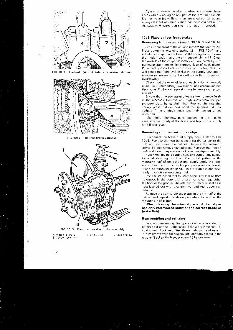
F I G 1 0 : 2 T h e r e a r b r a k e a d j u s t e r
Care must a lways be taken to observe absolute c lean-l i ness when wo rk i ng on any pa r t o f t he hyd rau l i c sys tem.Do no t l eave b rake f l u i d r n an unsea led con ta i ne r , anda lwavs d i sca rd anv f l u i d wh i ch has been d ra i ned ou t o ft he sys tem. A lways use t he f l u i d r ecommended .
1 0 : 3 F i x e d c a l i p e r f r o n t b r a k e s
Renew ing f r i c t i on pads ( see F IGS 10 : 3 and 10 : 4 ) :
Jack up t he f r on t o f t he ca r and remove t he road whee l .P ress down t he re ta i n i ng sp r i ng (2 i n F IG 10 :4 ) andw i t hd raw the sp l i t p i ns 3 . Remove t he sp r i ng and w r thd rawthe f r i c t i on pads 1 and t he an t i - squeak sh rms 11 . C leanthe ou t s i de o f t he ca l i pe r assemb ly and d r y ca re f u l l y w i t hpart icular at tentron to the exposed face of each piston.P ress each p r s ton back i n t o t he ca l i pe r , no t i ng t ha t t h i sw i l l cause t he f l u i d l eve l t o r r se i n t he supp l v t ank and i tmay be necessary to syphon of f some f lu id to preventove r f l ow ing .
Check that the re l ieved face of each piston is correct lyposi t ioned before f i t t ing new f r ic t ion pad assembl ies intothe i r bo res . F i t t he an t i squeak sh ims be tween each p r s tonano pao .
Ensure that the pad assembl ies are f ree 1o move f reelyin the recesses. Remove any high spots f rom the padp ressu re p l a te by ca re {u l f i l i ng . Rep lace t he re ta i n i ngsp r i ng , p ress i t down and i nse r t t he sp l i t p i ns . F i t newsp r i ngs i f t he o r i g i na l s have l os t t he i r t ens ion o r a reoamageo .
After t i t t ing the new pads operate the brake pedalseveral t imes to adjust the brake and top up the supplytank i f necessary.
R e m o v i n g a n d d i s m a n t l i n g a c a l i p e r :
D i sconnec t t he b rake f l u rd supp l y hose . Re fe r t o F IG10 :5 . Remove t he two bo l t s secu r i ng t he ca l i pe r t o t hehub and w i t hd raw the ca l i pe r . Dep ress t he re ta i n i ngsp r i ng 16 and remove t he sp l i t p i ns . Remove t he f r i c t i onpads and t he an t i - squeak sh ims . C lean t he ca l i pe rassemb ly .
Reconnec t t he f l u i d supp l y hose and suppo r t t he ca l i pe rt o avo id s t r a i n i ng t he hose . C lamp the p i s t on rn t hemoun t i ng ha l f o f t he ca l i pe r and gen t l y aDp l y t he f oo t -b rake , t hus f o r c i ng t he unc lamped p i s t on ou twa rds un t i li t can be removed by hand . Ho ld a su i t ab le con ta i ne rready t o ca t ch t he escap ing f l u i d .
Use a b l un t -nosed t oo l t o r emove t he f l u i d sea l 13 f r omits groove in the bore, takrng care not to damage ei therthe bore or the groove. The reta iner for the dust seal 1 4 isnex t l eve red ou t w i t h a sc rewd r i ve r and t he rubbe r sea lde tached .
Remove t he c l amp , r e f i t t he p i s t on i n t he r im -ha l f o f t hecal iper and repeat the above procedure to remove themoun t i ng ha l f p i s t on .
When c l ean ing t he i n t e rna l pa r t s o f t he ca l i pe ruse on l y me thy la ted sp i r i t o r t he co r rec t g rade o fb r a k e f l u i d .
Reassemb l i ng and re f i t t i ng :
Before commencing, the operator is recommended toob ta i n a se t o f new rubbe r sea l s . Take a d r y i nne r sea l ' 1
3 ,coat i t wi th Lockheed Disc Brake Lubr icant and ease r tinto i ts groove wi th the f ingers unt i l correct ly seated in thegroove. Slacken the bleeder screw 1 B by one turn.
I B r a k e d i s c 2 B l e e d s c r e w
F I G 1 0 : 3
K e y t o F i g 1 0 ; 33 C a l i p e r a s s e m b l y
1 1 2
F i x e d c a l i p e r d i s c b r a k e a s s e m b l y
F i G 1 0 : 1 T h e b r a k e ( A ) a n d c l u t c h ( B ) m a s t e r c y l i n d e r s
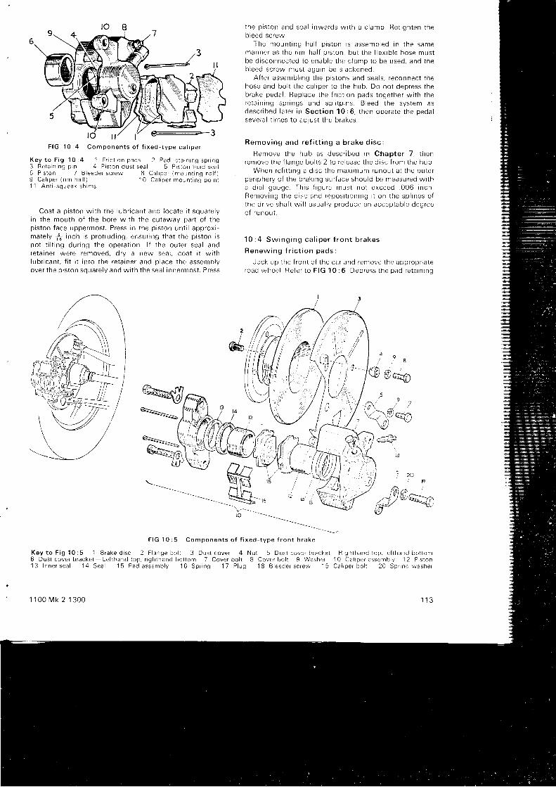
K e y t o F i g 1 0 : 4 1 F r i c t i o n p a d s 2 P a d r e t a r n r n g s p r r n g3 Re ta i n i ng p i n 4 P i s t on dus t sea l 5 P i s t on f l u i d sea l6 P i s t on 7 B leede r sc rew 8 Ca l rpe r (moun t i ng ha l f )9 Ca l i pe r ( r im ha l f ) 10 Ca l rpe r moun t i ng po rn r1 1 An t i squeak sh rms
Coa t a p i s t on w i t h t he l ub r i can t and l oca te i t squa re l yin the nrouth of the bore wi th the cutaway part of thep i s t on f ace uppe rmos t . P ress i n t he p i s t on un t i l app rox i -ma te l y t i n ch i s p ro t r ud ing , ensu r i ng t ha t t he p i s t on r sno t t i l t i ng du r i ng t he ope ra t i on . l f t he ou te r sea l andre ta i ne r we re removed , d r y a new sea l , coa t r t w r t hl ub r i can t , f i t i t i n t o t he re ta i ne r and p l ace t he assemb lyove r t he p i s t on squa re l v and w i t h t he sea l i nne rmos t . P ress
the p i s t on and sea l i nwa rds w r th a c l amp Re i i gh ten t hebleed screrry
The rnoun t i ng -ha l f p i s t on i s assemb led i n t he samemanne r as t he r im ha l f p r s ton . bu t t he f l ex i b l e hose mus tbe d r sconnec ted t o enab le t he c l amp t o be used , and t heb leed sc rew mus t aga in be s l ackened .
A f t e r assen rb l r ng t he p i s t on -s and sea l s , r econnec t t hehose and bo l t t he ca l i pe r t o t he hub . Do no t dep ress t heb rake peda l . Rep lace t he f r i c t i on pads t oge the r w i t h t here ta i n i ng sp r i ngs and sp l i t p i ns B leed t he sys tem asdesc r i bed l a t e r i n Sec t i on 10 :6 , t hen ope ra te t he peda lseve ra l t imes t o ad jus t t he b rakes .
Remov ing and re f i t t i ng a b rake d i sc :
Remove t he hub as desc r i bed rn Chap te r 7 . t henremove t he f l ange bo l t s 2 t o r e l ease t he d i sc f r on r t he hub .
When re f i t t i ng a d i sc t he max i r num runou t a t t he ou te rpe r i phe ry o f t he b rak i ng su r f ace shou ld be measu red w i t ha d i a l gauge . Th i s f i gu re mus t no t exceed . 006 i nch .Remov ing i he d i s . and reDos i t r on ing i t on t he sp l i nes o ft he d r i ve sha t t w i l l u sua l l y p roduce an accep tab le deg reeo f r unou t .
1 0 : 4 S w i n g i n g c a l i p e r f r o n t b r a k e s
R e n e w i n g f r i c t i o n p a d s
Jack up t he f r on t o f t he ca r and remove t he app rop r i a teroad whee l . Re fe r t o F IG 10 :6 Dep ress t he pad re ta i nn )g
. 9 .
flrao
, 2 /ao
to
t9
q
N u t 5 D u s t c o v e r i r r a c k e t R g h t h a n d t o p . l e f t h a n d b o t t o m8 C o v e r b o l t 9 W a s h e r 1 0 C a l i o e r a s s e m b l v 1 2 P i s t o n
1 8 B l e e d e r s c r e w 1 9 C a l i p e r b o l t 2 0 S p r i n g w a s h e r
1 1 3
(kcs,.-./7Vfrt-
F I G 1 0 : 5 C o m D o n e n t s o f f i x e d - t v D e f r o n t b r a k e
K e y t o F i g 1 0 : 5 1 B r a k e d i s c 2 F i a n g e b o h 3 D u s t c o v e r 46 D u s t c o v e r b r a c k e t ' - L e f l h a n d t o p , n g h t h a n d b o t t o m 7 C o v e r b o l t1 3 I n n e r s e a l 1 4 S e a l 1 5 P a d a s s e m b l y 1 6 S p r i n g 1 7 P l u g
1 1 0 0 M k 2 1 3 0 0
ld t/ tt/ e--3F I G 1 0 : 4 C o m p o n e n t s o f f i x e d - t y p e c a l i p e r

F IG 10 : 6 Componen ts o f sw ing ing - t vpe ca l i pe r
Key t o F i g 10 : 6 ' 1 F r i c t i on pads 2 Re ta i n i ng p rns3 Pad re ta i n i ng sp r i ng 4 P i s t on dus t sea i5 P i s l on 6 P i s t on f l u i d sea l 7 P i s t on cy l r nde rI P r s ton assemb ly r e ta i n rng c l r p
sp r i ng 3 and ex t rac t t he sp l i t p i ns 2 . W i t hd raw the f r i c t i onp a d s 1 .
Clean the exposed face o{ the piston, the recess i l rwh i ch t he mov ing pad s l i des and t he f ace o f t he ca l i pe ragainst which the f ixed pad rests. Press the piston backin to r t s cy l i nde r . no t i ng t ha t t h i s w i l l cause t he f l u i d l eve lto r ise in the supply tank and syphoning of f a quant i ty off lu id i f necessary to avoid an overf low.
F i t t he new pad assemb l i es , mak ing su re t ha t t he padoperated by the piston can move easi ly in the recess in thecai lper.
F i t t he r e ta i n i ng sp r i ng , p ress i t down and i nse r t t hesp l i t p i ns . l f a sp r i ng i s damaged o r has l os t i t s t ens ion a tshou ld be renewed .
Slacken the screw on the top of the cal iper adjacent tothe pivot p in boss, shown io the lef t o i the bleed screw InF IG 10 :7 . P ress down t he b rake peda l seve ra l t imes t ocentra l ize the brake pads on the disc and ret ighten thesc rew to a t o rque o f 65 t o 80 l b i n . Top up t he supp l y t anki f necessary.
Remov ing and d i sman t l i ng a cy l i nde r assemb ly :
Remove t he f r i c t i cn pads and re ta i ne r as j us t desc r i bed .D i sconnec t t he b rake f l u i d supp l y hose . Move t he sw ing ingcal iper lowards the centre of the car, re lease the reta in ingc l i p B and s l i de t he p i s t on assemb ly f r om the ca l i pe r , us i nga so f t - f aced hammer i f necessa ry .
Reconnec t t he f l ex i b l e supp l y hose and suppo r t t hecal iper to avoid stra i r r ing the hose. Press down gent ly onthe brake pedal unt i i the piston has emerged suf f ic ient lyfor i t to be removed by hand. The piston and seals ared i sman t l ed as desc r i bed i n t he p rev i ous Sec t i on .
Reassemb lv :
Re f i t t he sea l s as p rev i ous l y desc r i bed . C lean t he s l o t si n t he p i s t on and t he edges o f t he ca l i pe r . I nse r t t he p i s t onassemb lv i n t o t he ca l i pe r , b l eed sc rew to t he rea r , andre f i t t he r e ta i n i ng c l i p . Reconnec t t he f l ex i b l e hose and f i t
1 1 4
c
the f r ic t ion pads, b leed the systern as wi l l be descr ibed rnSec t i on 10 :6 and cen t ra l i ze t he pads by seve ra l app l i ca -t ions of the brake pedal . Top up the supply tank i f required.
Remov ing and rep lac i ng a ca l i pe r assemb ly :
Remove t he f r i c t i on pads . D i sconnec t t he supp l y hose .Remove t he two bo l t s secu r i ng t he ca l i pe r t o t he hub andl i f t of f .
Re lease t he re ta i n i ng sp r i ng c l i p and t ap t he p i s t onassemblv f rom the cal ioer wi th a sof t faced hammer.
Ref i t t ing the cal iper is a reversal of the above. Ensuretha t t he p i vo t p i n and t he s l i d i ng pa r t s o f t he ca l i pe r a refree f rom dir t and rust and f ree to move easi ly . Note thatthe th ick steel washer is f i t ted to the lower of the twosecu r i ng t he ca l i pe r and t ha t a sp r i ng washe r i s f i t t ed t oeach .
The c l ea rance unde r t he f oo t o f t he secu r i ng c l i p ( 5 i nF IG 10 :7 ) sho r - r l d no t exceed . 040 i nch . Th i s t o l e rance r sse t i n manu fac tu re and can be checked on l v when t hepaos are removeo.
B r a k e d i s c s :
These may be serv iced in the same manner as on { ixedca l i pe r assemb l res ( see Sec t i on 10 :3 ) , bu t no te t ha t t hemax imum runou t a t t he pe r i phe ry o f t he b rak i ng su r f aceshou ld no t exceed . 006 i nch .
1 0 : 5 S e r v i c i n g b r a k e s
Se rv i c i ng t he whee l cy l i nde r :
-Jack up the car under the rear subframe, remove theroad whee i and t ho rough l y c l ean t he b rake backp la te .D i sconnec t t he f l u i d supp l y hose as i ns t r uc ted i n Sec t i on1 0 : 8 .
K e y t o F i g 1 0 : 73 P i s t o n a s s e m b l y
1 B r a k e d i s c 2 B l e e d s c r e w4 S w i n g i n g c a l i p e r
II
II
lu_r\v
5 F i x e d t o s w r n g r n g c a l i p e r s e c u f l n g c l r p
F I G 1 0 : 7 S w i n g i n g c a l i p e r d i s c b r a k e

16 @ qg-,,a 6 7
*-o""-$
fl*@flryry
Unsc rew the b l eed sc rew f r om beh ind t he backo la te( 2 3 i n F I G 1 0 : 8 ) . R e m o v e t h e c i r c l i p f r o m t h e c y l i n o e rboss 24 p ro t r ud ing t h rough t he backp la te . Ren rove t hehub cap and nu t and , us i ng se rv i ce t oo l s 18G.304 and18G.3048 pu l l o f f t he b rake d rum and hub un i t . Removethe b rake shoes as desc r i bed l a t e r and l i f t ou t t he cy l i nde r .
Remove the rubber boots 22 and extract both pistons.Use the f ingers to remove the rubber p iston seals 21 . Cleana l l i n t e rna l pa r t s w i t h me thy la ted sp i r i t o r t he co r rec t g radeo f Lockheed b rake f l u i d .
A l l r ubbe r sea l s shou ld be renewed as shou ld any o the rpa r t show ing s i g ns o f wea r , p r t t i ng o r co r ros ron . pa r t i cu l a r l yt he p r s ton and cy l i nde r .
Reassemb ly i s ca r r i ed ou t i n t he reve rse o rde r t o d i s -man t l i ng w i t h a l l i n t e rna l pa r t s we t t ed w i t h b rake f l u ro .Use on l y t he f i nge rs t o f i t t he r ubbe r sea l s .
A{ter assembly, b leed the system as descr ibed inSec t i on 1 0 : 6 and ad lus t t he b rake shoes as i n Sec t i on1 O : 2
Se rv i c i ng t he b rake shoes :
Chock up t he f r on t whee l s . r e l ease t he handb rake . i ackup t he ca r unde r t he rea r sub f rame and remove t he i oadwnee t .
Remove t he hub cap and nu t and pu l l o f f t he d rum andhub un i t us i ng se rv i ce t oo l 18G.304 and 19G.3048 . A t
1 1 0 0 M k 2 1 3 0 0
F I G 1 0 : 9 R i g h t h a n d r e a r b r a k e a s s e m b l y
K e y t o F i g 1 0 : 9 1 H a n d b r a k e l e v e r 2 P u l l - o f f s p r r n g3 S t e a d y s p r i n g 4 P u l l - o f f s p r l n g 5 A d j u s r e r a s s e m o r y6 S t e a d y s p r i n g 7 H y d r a u l r c c y l i n d e r
1 1 5
*ry'd,tF I G 1 0 : 8 C o m p o n e n t s o f r e a r b r a k e
K e y t o F i g 1 0 : 8 1 B r a k e ' p l a t e 2 C a b l e a n d h o s e b r a c k e t 3 W a s h e r 4 P l a t e s c r e w 5 N u t 6 S p r i n g w a s h e r1 , S j ' t 9 9 g , s s e m O t y 8 L r n r n g 9 S h o e r e t u r n - s p r r n g 1 O S h o e r e t u r n s p l n g 1 ' 1 S r e a d y p r n 1 2 S t e a d y s p r i n g 1 3 W a s h e rl 4 H a n d b r a l ' . e e v e r 1 5 C y i n d e r b o o t 1 6 A d j u s t e r t a p p e t 1 7 W e d g e 1 8 N u t 1 9 W a s h e r 2 0 d y l r n d e r p i s t o n2 1 S e a l 2 2 E o o t 2 3 B l e e d s c r e w 2 4 C y l i n d e r c l i p
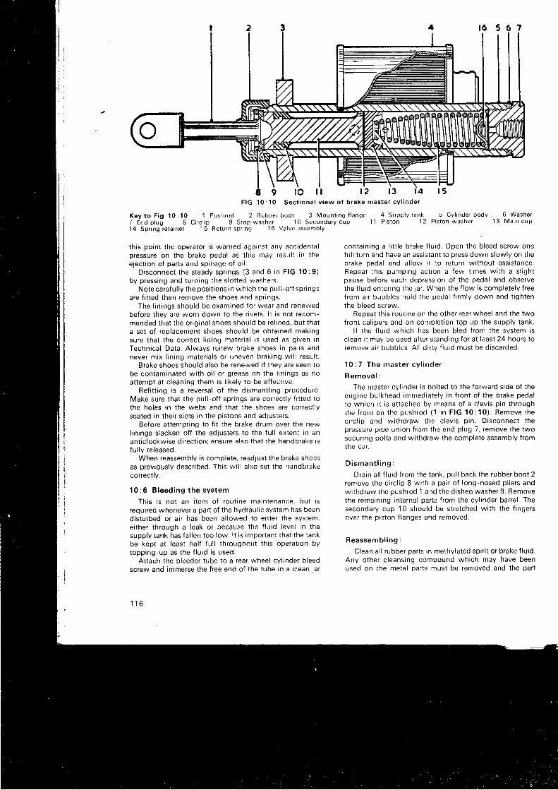
F I G 1 0 : 1 0 S e c t i o n a l v i e w o f b r a k e m a s t e r c y l i n d e r
K e y t o F i g 1 0 : 1 0 1 P u s h r o d 2 R u b b e r b o o t 3 M o u n t i n g f l a n g e 4 S u p p l y t a n k 5 C y l i n d e r b o d y 6 W a s h e r7 E n d p l u g 8 C i r c l i p 9 S r o p w a s h e r 1 0 S e c o n d a r y c u p
' 1 1 P i s t o n 1 2 P i s t o n w a s h e r 1 3 M a i n c u p
1 4 S p r i n g r e t a i n e r 1 5 R e t u r n s p r i n g 1 6 V a l v e a s s e m b l y
9 l o l l 1 2
th is point the operator is warned against any accidentalpressure on the brake pedal as th is may resul t in thee. iect ion of parts and spi l lage of o i l .
D i sconnec t t he s teady sp r i ngs (3 and 6 i n F IG 1 0 : 9 )by pressing and turning the s lot ted washers.
No te ca re fu l l y t he pos i t i ons i n wh i ch t he pu l l - o f f sp r i ngsare f i t ted then remove the shoes and spr ings.
The l i n i ngs shou ld be exam ined f o r wea r and renewedbefore they are worn down to the r ivets. l t is not recom-mended that the or ig inal shoes should be re l ined, but thata set of replacement shoes should be obtained makingsure that the correct l inrng mater ia l is used as given inTechnical Data. Always renew brake shoes in patrs andneve r m i x l i n i ng ma te r i a l s o r uneven b rak i ng w i l l r esu l t .
Brake shoes should also be renewed i f they are seen tobe contaminated wi th o i l or grease on the l in ings as noat tempt at c leaning them is l ikely to be ef fect ive.
Ref i t t ing is a reversal of the dismant l ing procedure.Make sure that the pul l -of f spr ings are correct ly f i t ted tothe holes in the webs and that the shoes are correct lyseated in their s lots in the pistons and adjusters.
Before at tempt ing to f i t the brake drum over the newl in ings s lacken of f the adjusters to the fu l l extent in anant ic lockwise di rect ion; ensure also that the handbrake rsfu l ly re leased.
When reassembly is complete, readjust the brake shoesas previously descr ibed. This wi l l a lso set the handbrakecorrect ly .
10 :6 B leed ing t he sys tem
This is not an i tem of rout ine maintenance, but isrequired whenever a part of the hydraul ic system has beendisturbed or a i r has been al lowed to enter the system,ei ther through a leak or because the f lu id level in thesupply tank has fa l len too low. l t is important that the tankbe kept at least hal f fu l l throughout th is operat ion bytopp ing -up as t he f l u i d i s used .
At tach the bleeder tube to a rear wheel cy l inder b leedscrew and immerse the f ree end of the tube in a c lean jar
1 1 6
f 6 5 6 7
13 f4 r 5
con ta i n i ng a l i t t l e b rake f l u i d . Open t he b l eed sc rew onef u l l turn and have an assrstant to press down slowly on thebrake pedal and al low i t to return wi thout assistance.Repea t t h i s pump ing ac t i on a f ew t imes w i t h a s l i gh tpause before each depression of the pedal and observethe f lu id enter ing the jar . When the f low is completely f reefrom air bubbles hold the pedal f i rmly down and t ightenthe bleed screw.
Repeat th is roui ine on the other rear wheel and the twofront cal ipers and on complet ion top up the supply tank.
l f the f lu id which has been bled f rom the system isc lean i t may be used af ter standing for at least 24 hours toremove a i r bubb les . A l l d i r t v f l u i d mus t be d i sca rded .
1 0 : 7 T h e m a s t e r c y l i n d e r
R e m o v a l :
The master cy l inder is bol ted to the forward s ide of theengine bulkhead immediately in f ront of the brake pedalto which r t is at tached by means of a c levis p in throughthe f r on t on t he push rod (1 i n F IG 10 :10 ) . Remove t hec i r c l i p and w i t hd raw the c l ev r s p i n . D i sconnec t t hepressure pipe union f rom the end plug 7, remove the twosecur ing bol ts and wi thdraw the complete assembly f romIne ca r .
D i s m a n t l i n g :
D ra in a l l f l u i d f r om the t ank . pu l l back t he rubbe r boo t 2remove t he c i r c l i p 8 w i t h a pa i r o f l ong -nosed p l i e r s andwithdraw the pushrod 1 and the dished washer 9. Removethe remaining internal parts f rom the cyl inder barrel . Thesecondary cup 10 should be stretched wi th the f ingersover the piston f langes and removed.
Reassemb l i ng :
Clean al l rubber parts in methylated spir i t or brake f lu id.Any other c leansing compound which may have beenused on the metal oarts must be removed and the par l
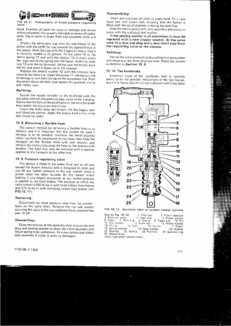
r - - r c r i r - f f i l m \ *0!iJ ml 6,8m0 o0nDmmier,lrD tilil ..iemY|EU
--s\Y'vvt ntnll VWI:
F IG 10 :11 Componen ts o f b rake p ressu re regu ta t i ngva l ve
d r i ed . Exam ine a l l pa r t s f o r wea r o r damaqe and renewwhere necessary; i t is ususal ly desirable to re-new al l ruooerpa r t s . D ip a l l pa r t s r n b rake f l u i d and assemb le wh i l e s t i l lwet .
Stretch the secondary cup over the end f lanqe of thepiston wi th the l ipt f the cup towards the opposi te end ofthe piston. Work the cup wi th the f ingers to ensure that i trs correct ly seated In i ts groove. Fi t the valve 16 to there tu rn sp r i ng 15 and w i t h t he re ta i ne r . l 4 i n p l ace i nsenthe l a rge end o f t he sp r i ng i n t o t he ba r re l . I nse r t t he marncup 13 wi th the l ip foremost, tak ing care not to turn bacKthe l ip, and press i t down on to the reta iner.
Rep lace t he d i shed washe r 12 w i t h t he concave f acetowa rds t he ma in cup . I nse r t t he p i s t on 11 , t ak i ng ca re no tto damage or turn back the l ip on the secondarV Cup. pushthe piston down the bore and replace the pushrod, c i rc l ipand rubber boot .
Re f i t t i ng :
Secu re t he mas te r cy l i nde r t o t he bu l khead w i t h t hetwo bol ts and ref i t the pressure pipe union to the end plug.Ensure that the fork on the pushrod is in l ine wi th the Dedall eve r and f i t t he c l ev i s p i n and c i r c l i p .
Check the brake shoe adjustment. F i l l the supply tankand bleed the system. Apply the brakes hard a few t imesand check for leaks.
1 0 : 8 B e m o v i n g a f l e x i b l e h o s e
The correct method for removing a f lex ib le hose is asfol lows, and i t is important that th is rout ine be used i fdamage is to be avoided: Unscrew the metal p iperrneunion nut f rom i ts connect ion to the hose, then hold rnehexagon on t he f l ex i b l e hose w i t h one spanne r andremove the locknut secur ing the hose to the bracket wi thanother. The hose may now be removed wi th a soannerapp l i ed t o t he hexagon a t t he o the r end .
10 :9 P ressu re regu la t i ng va l ve
This device is f i t ted in the brake f lu id l ine on al l carsexcept the Aust in America and is designed to c lose andcut of f any fur ther pressure to the rear wheels when apreset value has been reached. By th is means wheellocking is very largely prevented, as anV fur ther oressureis appl ied to the f ront brakes. The pressure ut *h ich thevalve c loses is 450 lb/sq in wi th f ixed cal iper f ront brakesand 375 l b / sq i n w i t h sw ing ing ca l r pe r t ype b rakes ( seeF I G 1 0 : 1 1 ) .
Remov ing :
Disconnect the three pressure l ines f rom the connec_t rons on t he va l ve body . Remove t he nu t and wasne rsecur ing the valve to the rear subframe f ront crossmemberand l i f t of f .
D i s m a n t l i n g :
Clean the exter ior of the assembly then remove the endplug and seal ing washer to a l low the valve assemblv anoreturn spr ing to be wi thdrawn. Fi t a new piston and rubberseal assembly i f e i ther is worn or damaqed.
1 1 0 0 M k 2 1 3 0 0
R e a s s e m b l i n g :
C lean and l ub r i ca te a l l pa r t s i n b rake f l u i d . F i t a newtape r sea l and p i s t on sea l , ensu r i ng t ha t t he f o rmer i sf i t ted wi th the smal l d iameter enter ing the bore f i rs t .
Re f i t t he r e tu rn sp r i ng and va l ve assemb ly and secu re rnp lace w i t h t he end p l ug and washe r .
l f t he sea l i ng washe r i s o f a l um in i um i t mus t bereplaced wi th a new copper washer. At the samet ime f i t a new end p l ug and a new sho r t p i pe f r omthe regu la t i ng va l ve t o t he chass i s .
R e f i t t i n g :
Secure the valve assembly to the subframe crossmemberand reconnect the three pressure l ines. Bleed the svstemas de ta i l ed r n Sec t i on 10 : 6
' 10 : 10 The handb rake
Excessive t ravel of the handbrake lever is normalytaken up by the per iodic adjustment of the rear brakes,but i f i t is found that th is is not suf f ic ient and i t has been
20
2122
23
24
25
5678
I101112
F I G 1 0 ; 1 2 S e c t i o n a l v i e w o f t a n d e m m a s t e r c y l i n d e r
K e y t o F i g 1 0 : 1 2 ' 1 F i l l e r c a p 2 p l a s r i c r e s e r v o r r
3 R e s e r v o i r s e a l s 4 M a i n c u p 5 p i s l o n w a s h e r6 P i s l o n 7 M a i n c u p 8 S p r i n g g p i s t o n l i n k 1 0 p i n1 1 P i n r e t a i n e r 1 2 M a i n c u p 1 3 p i s t o n w a s h e r' 1 4 C i r c l i p 1 5 C u D 1 6 C i r c t i p 1 7 p j s r o n1 8 Spr ing re ta iner 1 9 S top washer 20 Wasner? 1 P " : i " s . 2 2 S p r i n s 2 3 i , u s h r o d 2 4 S p i r o t o i i r n gz c h u o o e r b o o t( E a r l y t y p e p i s t o n s h o w n i n s e t )
1 1 7
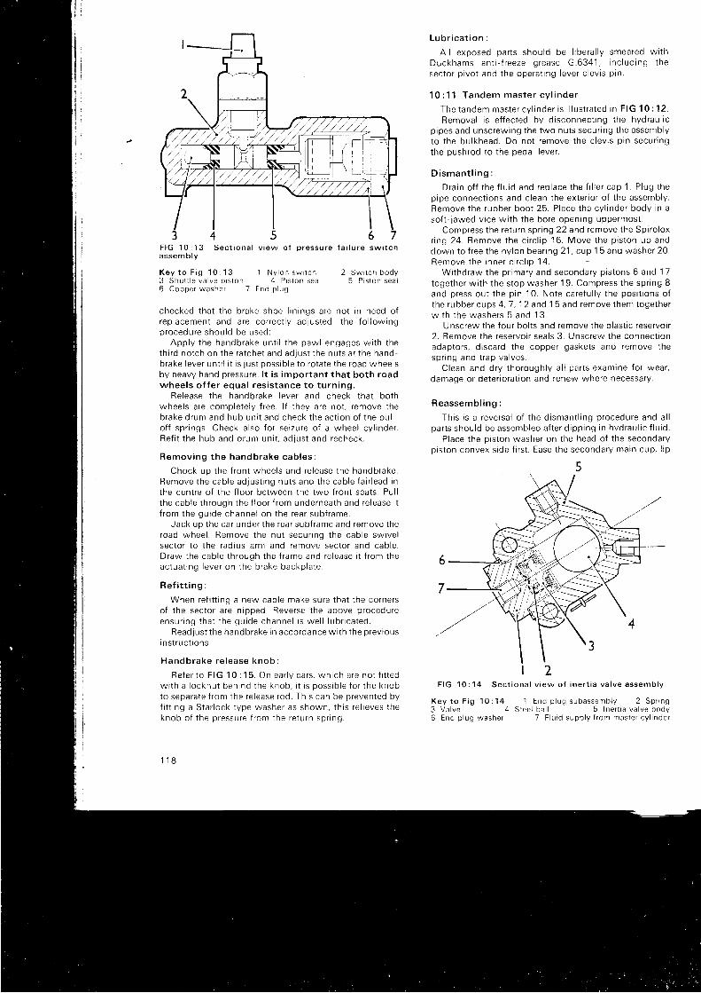
F I G 1 0 : 1 3 S e c t i o n a l v i e w o f o r e s s u r e f a i l u r e s w i t c ha s s e m b l v
K e y t o F i g 1 0 : 1 3 1 N y l o n s w r t c h3 S h u t t l e v a l v e p r s t o n 4 P r s t o n s e a l6 C o p p e r w a s h e r 7 E n d p l u g
2 Swi tch body5 P i s l o n s e a l
checked t ha t t he b rake shoe l i n i ngs a re no t i n need o fr ep lacemen t and a re co r rec t l y ad lus ted , t he f o l l ow ingp rocedu re shou ld be used :
App l y t he handb rake un t i l t he paw l engages w i t h t heth i r d no t ch on t he ra t che t and ad lus t t he nu t s a t t he handbrake lever unt i l i t is just possrble to rotate the road wheelsby heavy hand pressure. l t is important that both roadwhee l s o f f e r equa l r es i s t ance t o t u rn i ng .
Re lease t he handb rake l eve r and check t ha t bo thwheels are completely f ree. l f they are not , remove theb rake d rum and hub un i t and check t he ac t i on o f t he pu l l -o f f sp r i ngs . Check a l so f o r se i zu re o f a whee l cy l i nde r .Re f i t t he hub and d rum un i t , ad j us t and recheck .
Remov ing t he handb rake cab les :
Chock uo t he f r on t whee l s and re l ease t he handb rake .Remove t he cab le ad jus t i ng nu t s and t he cab le f a i r l ead rnthe centre of the f loor between the two f ront seats. Pul lt he cab le t h rough t he f l oo r f r om unde rnea th and re l ease i tf r om the gu ide channe l on t he rea r sub f rame .
Jack up t he ca r unde r t he rea r sub f rame and remove t heroad whee l . Remove t he nu t secu r rng t he cab le sw i ve lsector to the radius arm and remove sector and cable.D raw the cab le t h rough t he f r ame and re l ease i t f r om theac tua t i ng l eve r on t he b rake backp la te .
R e f i t t i n g :
When ref i t t ing a new cable make sure that the cornersof the sector are nipped. Reverse the above procedureensu r i ng t ha t t he gu ide channe l i s we l l l ub r i ca ted .
Read jus t t he handb rake i n acco rdance w i t h t he p rev i ousI ns t r u c t r ons .
Handb rake re l ease knob :
Re fe r t o F IG 10 : 15 . On ea r l y ca r s , wh i ch a re no t f i t t edw i t h a l ocknu t beh ind t he knob , i t i s poss ib l e f o r t he knobto sepa ra te f r om the re l ease rod . Th i s can be p reven ted byf i t t i ng a S ta r l ock t ype washe r as shown , t h i s r e l i eves t heknob o f t he p ressu re f r om the re tu rn sp r i ng .
1 1 8
L u b r i c a t i o n :
A I I exposed pa r t s shou ld be l i be ra l l y smea red w r thDuckhams an t i - f r eeze g rease G .6341 , i nc l ud ing t hesec to r p i vo t and t he ope ra t i ng l eve r c l ev i s p i n .
1 0 : 1 1 T a n d e m m a s t e r c v l i n d e r
The t andem mas te r cy l i nde r i s i l l u s t r a ted i n F IG 10 : 12 .Remova l i s e f f ec ted by d i sconnec t i ng t he hyd rau l i c
p i pes and unsc rew ing t he two nu t s secu r i ng t he assemb lyto t he bu l khead . Do no t r emove t he c l ev i s p i n secu r i ngthe pushrod to the pedal lever.
D i s m a n t l i n g :
D ra in o f f t he f l u i d and rep lace t he f i l l e r cap 1 . P lug t hep ipe connec t i ons and c l ean t he ex te r i o r o f t he assemb ly .Remove t he rubbe r boo t 25 . P lace t he cv l i nde r bodv i n aso f t - j awed v i ce w i t h t he bo re open ing uppe rmos t .
Compress the return spr ing 22 and remove the Spiro loxr i ng 24 . Remove t he c i r c l i p 16 . Move t he p i s t on up anddown t o { r ee t he ny l on bea r i ng 21 , cup 1 5 and washe r 20 .Remove t he i nne r c i r c l i o 14 .
W i thd raw the p r ima ry and seconda ry p i s t ons 6 and 17toge the r w i t h t he s top washe r 19 . Compress t he sp r i ng 8and p ress ou t t he p i n 10 . No te ca re fu l l y t he pos i t i ons o ft he rubbe r cups 4 ,7 , 12 and 1 5 and remove t hem toge the rw i t h t he washe rs 5 and 13 .
Unscrew the four bol ts and remove the plast ic reservoir2 . Remove t he rese rvo i r sea l s 3 . Unsc rew the connec t i onadaptors, d iscard the copper gaskets and remove thesp r i no and t r ap va l ves .
C lean and d r y t ho rough l y a l l pa r t s exam ine f o r wea r ,damage or deter ioratron and renew where necessary.
Reassemb l i ng :
Th i s i s a r eve rsa l o f t he d i sman t l i ng p rocedu re and a l lpa r t s shou ld be assemb led a f t e r d i pp ing i n hvd rau l i c f l u rd .
Place the piston washer on the head of the secondaryp i s t on convex s i de f i r s t . Ease t he seconda ry ma in cup , l i p
(
t 2F I G 1 0 : 1 4 S e c t i o n a l v i e w o f i n e r t i a v a l v e a s s e m b l y
K e y t o F i g 1 0 : 1 4 1 E n d p l u g s u b a s s e m b l y 2 S p r i n g3 Va lve 4 S lee l ba l l 5 Iner t ia va lve body6 E n d p l u g w a s h e r 7 F l u i d s u p p l y f r o m m a s t e r c y l i n d e r
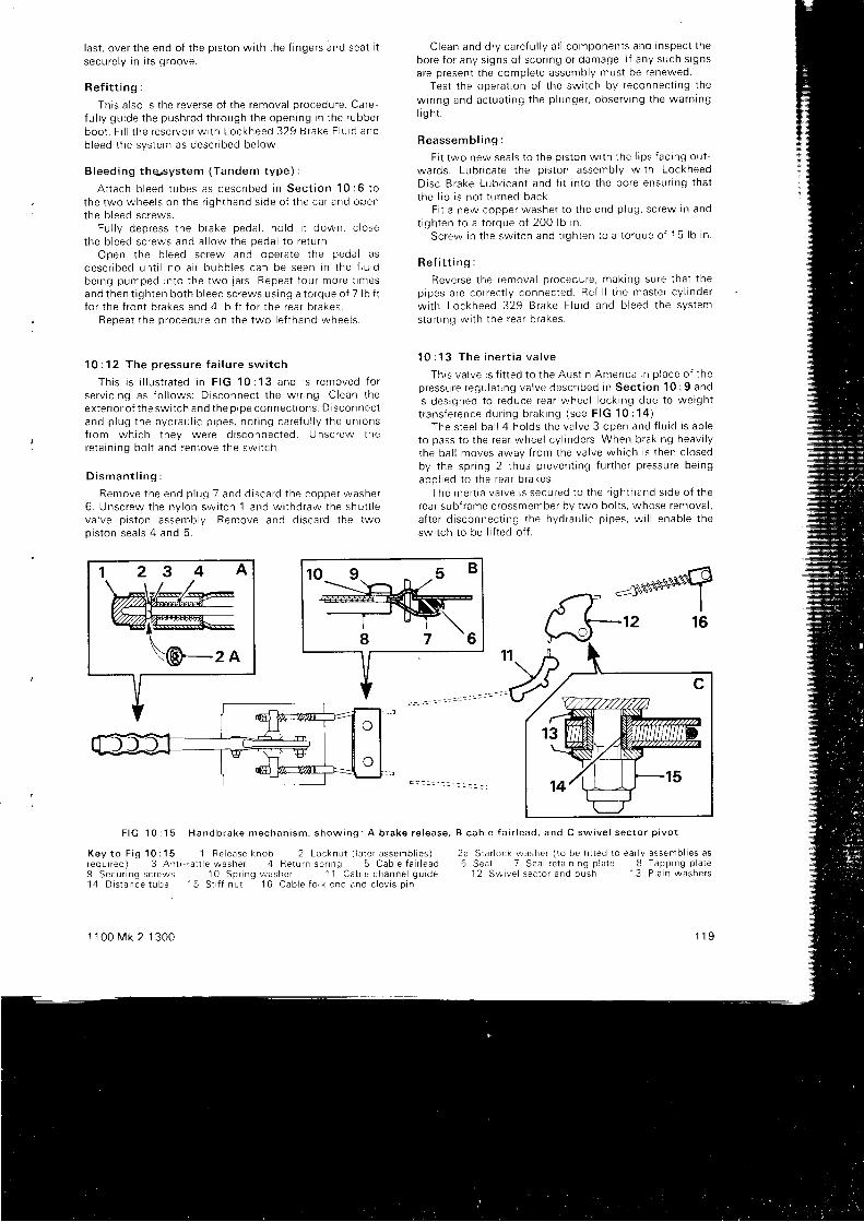
l a s t , ove r t he end o f t he p i s t on w i t h t he f i nge rs and sea t i tsecu re l y i n i t s g roove .
R e f i t t i n g :
This a lso is the reverse of the removal procedure. Care-f u l l y gu ide t he push rod t h rough t he open ing i n t he rubbe rboo t . F i l l t he r ese rvo r r w r t h Lockheed 329 t s rake F lu i d andb leed t he sys tem as desc r i bed be low .
B leed ing t hq , sys tem (Tandem t ype ) :
A t t ach b l eed t ubes as desc r i bed i n Sec t i on 10 :6 t othe two whee l s on t he r i gh thand s i de o f t he ca r and openthe b l eed sc rews .
Fu l l y dep ress t he b rake peda l , ho l d i t down , c l osethe b l eed sc rews and a l l ow t he peda l t o r e tu rn .
Open t he b l eed sc rew and ope ra te t he peda l asdesc r i bed un t i l no a i r bubb les can be seen i n t he f l u i dbe ing pumped i n to t he two 1a rs . Repea t f ou r mo re t imesand t hen t i gh ten bo th b l eed sc rews us i ng a t o rque o f 7 l b f tf o r t he f r on t b rakes and 4 l b f t f o r t he rea r b rakes .
Repea t t he p rocedu re on t he two l e f t hand whee l s .
1 0 : 1 2 T h e p r e s s u r e f a i l u r e s w i t c h
Th i s i s i l l u s t r a ted i n F IG 10 :13 and i s r emoved f o rse rv i c i ng as f o l l ows : D i sconnec t t he w r r i ng . C lean t heex teno r o f t he sw i t ch and t he p i pe connec t t ons . D i s connec tand p l ug t he hyd rau l i c p i pes , no t i ng ca re fu l l y t he un ionsi r om wh i ch t hey we re d i sconnec ted . U nsc rew there ta i n i ng bo l t and remove t he sw i t ch .
D i s m a n t l i n g :
Remove t he end p l ug 7 and d i sca rd t he coppe r washe r6 . Unsc rew the ny l on sw i t ch 1 and w r thd raw the shu t t l eva l ve p i s t on assemb ly . Remove and d i sca rd t he twop i s ton sea l s 4 and 5 .
K e y t o F i g 1 0 : 1 5 1 R e l e a s e k n o b 2 L o c k n u t ( l a t e r a s s e m b l i e s )r e q u i r e d ) 3 A n t i - r a t t l e w a s h e r 4 R e t u r n s p r i n g 5 C a b l e f a i r l e a d9 S e c u r i n g s c r e w s 1 0 S p r i n g w a s h e r 1 1 C a b l e c h a n n e l g u r d e' 1 4 D i s t a n c e t u b e 1 5 S t r i f n u t 1 6 C a b l e f o r k e n d a n d c l e v i s p i n
1 1 0 0 M k 2 1 3 0 0
Clean and d r y ca re f u l l y a l l componen ts and i nspec t t hebo re f o r any s i gns o f s co r i ng o r damage . l f any such s i gnsare present the complete assembly must be renewed.
Tes t t he ope ra t i on o f t he sw i t ch by r econnec t i ng t he
w inng and ac tua t i ng t he p l unge r , obse rv i ng t he wa rn ingl i g h t .
R e a s s e m b l i n g :
F i t two new sea l s t o t he p i s t on w t t h t he l i p s f ac i ng ou t -wa rds . Lub r i ca te t he p i s t on assemb ly w i t h LockheedD isc B rake Lub r r can t and f i t i n t o t he bo re ensu r i ng t ha tt he l i p i s no t t u rned back .
F i t a new coppe r washe r t o t he end p l ug , sc rew i n andt i gh ten t o a t o rque o f 200 l b i n .
Sc rew i n t he sw i t ch and t r gh ten t o a t o rque o f 15 l b i n .
Re f i t t i ng :
Reve rse t he remova l p rocedu re , mak ing su re t ha t t hep ipes a re co r rec t l y connec ted . Re f i l l t he mas te r cy l i nde rw i t h Lockheed 329 B rake F lu i d and b l eed t he sys tem
s ta r t i ng w i t h t he rea r b rakes .
1 0 : 1 3 T h e i n e r t i a v a l v e
Th i s va l ve i s f i t t ed t o t he Aus t i n Amer i ca i n p l ace o f t hep ressu re regu la t i ng va l ve desc r i bed i n Sec t i on 10 :9 andi s des igned t o r educe rea r whee l l ock i ng due t o we igh tt r a n s { e r e n c e d u r i n g b r a k i n g ( s e e F I G 1 0 : 1 4 ) .
The s tee l ba l l 4 ho lds t he va l ve 3 open and f l u i d i s ab leto pass t o t he rea r whee l cy l i nde rs . When b rak i ng heav i l yt he ba l l moves away f r om the va l ve wh i ch i s t hen c l osedby t he sp r i ng 2 t hus p reven t i ng f u r t he r p ressu re be ingapp l i ed t o t he rea r b rakes .
The rne r t i a va t ve i s secu red t o t he r i gh thand s i de o f t herea r sub f r ame c rossmember by two bo l t s , whose remova l ,a f t e r d i sconnec t i ng t he hyd rau l i c p i pes , w i l l enab le t heswitch to be l i f ted of f .
S t a r o c k w a s h e r ( t o b e f i t t e d t o e a r l y a s s e m b l i e s a sS e a l 7 S e a l r e t a r n i n g p l a t e 8 T a p p i n g p l a t el 2 S w i v e l s e c t o r a n d b u s h 1 3 P l a i n w a s h e r s
1 1 9
F I G 1 0 : 1 5 H a n d b r a k e m e c h a n i s m , s h o w i n g : A b r a k e r e l e a s e , B c a b l e f a i r l e a d , a n d C s w i v e l s e c t o r p i v o t
2 a6
2 3 4
D i s m a n t l i n g :
Remove t he end p l ug assemb ly 1 , washe r 6 and s tee lba l l 4 . C ean t he body 5 and t he s tee l ba l l w i t h b rake f l u ro .I nspec t a l l pa r t s mos t ca re fu l l y and renew anv t ha t a re no ti n pe r f ec t cond i t r on .
R e a s s e m b l i n g :
l nse r t t he s tee l ba l l i n t o t he body . Sc rew i n t he va l ve andend p l ug , us i ng a new coppe r washe r . Ensu re t ha t t hesea t i ng f aces on bo th body and end p l ug a re c l ean andundamaged and t i gh ten t o a t o rque o f 50 l b f t .
R e f i t t i n g :
When bo l t i ng t he va l ve t o t he sub f r ame make su re t ha tr t i s co r rec t l y pos i t r oned w i t h t he mark i ng FRONT i n t her i gh t d i r ec t i on .
F i l l t he mas te r cy l r nde r w i t h Lockheed 329 B rake F lu toand b l eed t he sys tem as a l r eady desc r i bed . I nspec t t hei ne r t i a va l ve f o r f l u i d l eaks bo th w i t h t he peda l f u l l ydepressed and wi th the system at rest .
1 0 : 1 4 T y p e 6 v a c u u m s e r v o u n i t
Th i s componen t , wh i ch maV be f i ned as an op t i ona lex t r a , i s connec ted i n t he hyd rau l i c c l r cu i t be lween t hemas te r cy l i nde r and t he whee l cy l i nde rs . l t s pu rpose i s t ouse t he dep ress ion i n t he i n l e t man i f o l d t o augmen t t hep ressu re exe r t ed by t he d r i ve r on h i s b rake peda l . l t doesno t jmp rove t he pe r f o rmance o f t he b rakes , bu t enab les as tanda rd o f b rak i ng t o be ob ta i ned w i t h l ess peda lp ressu re . l t t s no t r ecommended t ha t t he home ope ra to rshou ld d i sman t l e t he se rvo un i t bu t t ake t t t o h i s se r v i ceagen t f o r a t t en t i on i n t he even t o f f a i l u re . The un i t r sd e s i g n e d t o ' f a i l s a f e ' a n d i f t h e v a c u u m m e c h a n i s mshou ld b reak down . f u l l b rak i ng i s s t i l l a va i l ab l e bu t w i t hcons ide rab l y mo re p ressu re requ i r ed on t he b rake peda l .
An i t em o f ma in tenance wh i ch may be ca r r i ed ou t i s t herenewa l o f t he a i r f i l t e r unde r t he snap f i t t i ng dome shapedcove r . Th i s r equ i r es a t t en t i on a t abou t t he same t ime asthe b rake f r i c t i on l i n i ngs .
120
U n i t r e m o v a l :
Undo bo th t he hyd rau l i c p i pe un ions f r om the un i t andre l ease t he vacuum p ipe f r om the non - re tu rn va l ve i n t heu n r t c a s r n g .
Unsc rew the two nu t s f r om the moun t i ng s tuds .S lacken t he c l amp round t he neck o f t he s l ave cy l i nde rand l i f t ou t t he un i t comp le te . l t w i l l be no ted t ha t t heho les i n t he moun t i ng b racke t a re s l o t t ed t o f ac i l i t a t e t h i s .
Re f i t t i ng i s t he reve rse o f t he above , a f t e r wh i ch t heb rake sys tem mus t be b l ed .
1 0 : 1 5 F a u l t d i a g n o s i s
( a ) ' S p o n g y ' p e d a l
1 Leak i n t he sys tem2 Worn mas te r cy l i nde r3 Leak ing whee l cy l i nde rs4 A i r i n t he f l u i d sys tem5 Gaps be tween t he rea r shoes and - t he unde rs i de o f
l i n i n g s
(b ) Excess i ve peda l movemen t' 1
Check 1 and 4 i n ( a )2 Excess i ve l i n i ng wea r3 Ve ry l ow f l u i d l eve l i n supp l y t ank4 Too much f ree movement of pedal
( c ) B rakes g rab o r pu l l t o one s i de
1 D i s to r t ed d i scs o r d rums2 We t o r o i l y pads o r I i n i ngs3 Rear brake backplate loose4 D i sc l oose on hub5 Worn suspens ion o r s t ee r i ng connec l t ons6 M ixed l i n i ngs o f d i f f e ren t g rades7 Uneven tyre pressures8 B roken shoe re tu rn sp r i ngs9 Se i zed handb rake cab le
10 Se i zed p i s t on rn whee l cy l i nde r1 1 Loose ca l i pe r f i x i ngs
CHAPTER 11
THE ETECTRICAL SYSTEM
1 1 : 1 D e s c r i p t i o n11 : 2 The ba t t e r y1 1 : 3 The gene ra to r1 1 : 4 T h e a l t e r n a t o r11 : 5 S ta r t e r mo to r t ype M35G11 : 6 The con t ro l box1 1 : 7 Fuses1 1 : 8 F l a s h e r u n i t
1 1 : 1 D e s c r i p t i o n
A 12-vol t e lectr ical system is used wi th posi t ive earth_ing on al l models except 1970 Aust in America models orwhen al ternator type 16ACR is f i t ted. These cars haveNEGATIVE ea r t h rng and w i r i ng d i ag rams cove r i ng t hewhole range wi l l be found in Technical Data at the enoo f t he manua l .
The regulator box comprises three uni ts to contro l thecha rg ing c i r cu i t s ; a cu t -ou t , a cu r ren t r egu la to r ano avol tage regulator . These are adjustable, but i t is st ressedtha t as w i t h a l l o t he r e l ec t r i ca l un i t s t he equ ipmen trequ i r ed may no t be read i l y ava l l ab l e t o t he home ope ra ro rfor test ing and serv ic ing. l t cannol be too strongly recom-mended that defect ive electr ical equipment should beserviced by a qual i f ied serv ice stat ign or replaced bytaking advantage of the very extensive exchanqe faci l l t iesof fered by the manufacturers.
The gene ra to r o r a l t e rna to r i s moun ted on t he r i qh t o ft he cy l i nde r b l ock and i s d r i ven f r om the c ranksha f t pu r reyby t he same be l t as d r i ves t he wa te r pump and coo l i ng i an .The mount ing is adjustable to a l low the correci bel ttensron to be obtained.
Doub le d i pp ing sea led -beam head lamps a re used f o r t heHome market , wi th a l ternat ive arrangements for other
1 1 0 0 M k 2 1 3 0 0
1 1 : 9 W i n d s c r e e n w i p e r s1 1 : 1 0 T h e h e a d l a m p s1 1 : 1 1 T h e h o r n11 : 12 Fue l and t empe ra tu re gauges1 1 : 1 3 l m p u l s e t a c h o m e t e r11 : 14 S ta r t e r mo to r t ype M35J1 1 : 1 5 A l t e r n a t o r 1 6 A C R1 1 : 1 6 F a u l t d i a g n o s i s
coun t r i es acco rd i ng t o l oca l r egu la t i ons . I ns t r umen ts a revo i t age con t ro l l ed by a b i me ta l r es i s t ance un i t wh i chensu res a s t ab i l i zed vo l t age supp l y .
1 1 : 2 T h e b a t t e r y
. Th i s i s a 12 , vo l t l ead /ac i d t ype and i s moun ted on t her i gh thand w ing va lance unde r t he bonne t . The ba t t e r yrequ i r es l i t t l e ma in tenance . bu t i t i s impo r tan t t ha t i t Deregu la r l y a t t ended t o .
The top of the bat tery should be kept c lean and dry, anoany corrosion here or on adlacent areas should beremoved wi th a weak ammonia solut ion and the af fectedpa r t s be ing a f t e rwa rds pa in ted w i t h an t i - su l phu r i c oa in t .l f the termtnal posts are corroded the cables should oeremoved, c leaned and replaced af ter smear ing them wrtnpetro leum je l ly . Take of f the mani fo ld to check for cracksas th is is a f requent cause of e lectro lyte leakage andcorrosron.
The l eve l o f t he e l ec t r o l y t e shou ld be ma in ta i ned i us tabove the tops of the separators by the addir ion ofd i s t i l l ed wa te r . Neve r add ac i d . l f a t any t ime i t i s r eou i r edto use ac i d f o r f i l l i ng a ba t t e r y ce l l a lways m ix t heelectro lyte to the correct gravi ty by s lowly adding acid tothe water and never water to the acid.
121
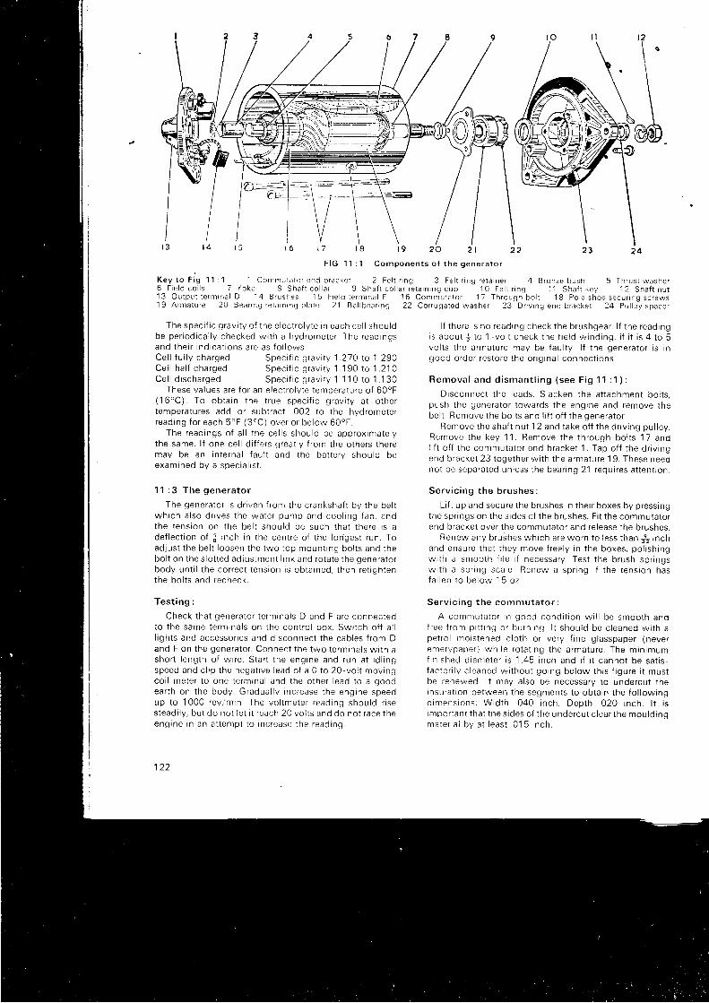
f 3 t 4 1 5 1 6 t ' 7 l 8 t 9 2 0 2 1 2 2
F IG 1 ' l : 1 Componen ts o f t he gene ra to r
Key t o F i g 11 : 1 1 Commuta to r end b racke t 2 Fe l t r i ng 3 Fe l t r r ng re ta i ne r
The spec i f i c g rav i t y o f t he e l ec t r o l y t e i n each ce l l shou ldbe pe r i od i ca l l y checked w i t h a hyd rome te r . The read ingsand t he i r i nd i ca t i ons a re as f o l l ows :
6 F i e l d c o i l s 7 / o k e 8 S h a f t c o l a r 9 S h a f t c o l l a r r e t a i n i n g c u p ' 1 0 F e l t r i n g 1 1 S h a f r k e y 1 2 S h a f t n u t1 3 O u t p u t t e r m r n a l D 1 4 B r u s h e s 1 5 F i e l d t e r m i n a l F 1 6 C o m m u t a t o r 1 7 T h r o u g h b o l t 1 8 P o l e s h o e s e c u r r n q s c r e w s1 9 A r m a t u r e 2 0 B e a r r n g r e t a r n l n g p l a t e 2 1 B a l l b e a r i n g 2 2 C o r r u g a t e d w a s h e r 2 3 D r i v i n g e n d b r a c k e t 2 4 P u l l e y s p a c e r
Ce l l f u l l y cha rgedCe l l ha l f cha rgedCe l l d i s cha rged
Speci f ic gravi ty 1 .210 to 1 290Spec i f i c g rav i t y 1 . 1 90 t o 1 . 210S p e c i f i c g r a v i t y 1 1 I 0 t o 1 . 1 3 0
These va lues a re f o r an e l ec t r o l y t e t empe ra tu re o f 60oF(16 "C) To ob ta i n t he t r ue spec i f i c g rav i t y a t o t he rt empe ra tu res add o r sub t rac t . 002 t o t he hyd rome te rread ing f o r each 5 'F ( 3 "C ) ove r o r be low 60oF .
The read ings o f a l l t he ce l l s shou ld be app rox ima te l yt he same . l f one ce l l d i f f e r s g rea t l y f r om the o the rs t he remay be an i n t e rna l f au l t and t he ba t t e r y shou ld beexam ined by a spec ia l i s t .
1 1 : 3 T h e g e n e r a t o r
The gene ra to r i s d r i ven f r om the c ranksha f t by t he be l twh i ch a l so d r i ves t he wa te r pump and coo l i ng f an . andthe t ens ion on t he be l t shou ld be such t ha t t he re i s ade f l ec t i on o f i i n ch i n t he cen t re o f t he l o r i ges t r un . Toad jus t t he be l t l oosen t he two t op moun t i ng bo l t s and t hebo l t on t he s l o t t ed ad jus tmen t l i n k and ro ta te t he gene ra ro rbody un t i l t he co r rec t t ens ion i s ob ta i ned , t hen re t i gh tenthe bo l t s and recheck .
Tes t i ng :
check t ha t gene ra to r t e rm ina l s D and F a re connec tedto t he same te rm ina l s on t he con t ro l box . Sw i t ch o f f a l ll i gh t s and accesso r i es and d i sconnec t t he cab les f r om Dand F on t he gene ra to r . Connec t t he two t e rm ina l s w i t h asho r t l eng th o f w r re . S ta r t t he eng ine and run a t i d l i ngspeed and c l i p t he nega t r ve l ead o f a 0 t o 20 , vo l t mov ingco i l me te r t o one t e rm ina l and t he o the r l ead t o a goodea r th on t he body . G radua l l y i nc rease t he eng ine speedup t o 1000 rev l 'm in . The vo l lme te r r ead rng shou ld r r ses tead i l y , bu t do no t l e t i t r each 2O vo l t s and do no t r ace t heenq ine i n an a t t emp t t o i nc rease t he read ing .
l l z
2 3
4 B r o n z e b u s h
2 4
5 T h r u s t w a s h e r
l f t he re i s no read ing check t he b rushgea r . l f t he r ead ingi s abou t + t o 1 - vo l t check t he f i e l d w ind ing , i f i t i s 4 t o 5vo l t s t he a rma tu re may be f au l t y . l f t he gene ra to r i s i ngood o rde r r es to re t he o r i g i na l connec t i ons .
R e m o v a l a n d d i s m a n t l i n g ( s e e F i g 1 1 : 1 ) :
D i sconnec t t he l eads . S lacken t he a t t achmen t bo l t s ,push t he gene ra to r t owa rds t he eng ine and remove t hebe l t . Remove t he bo l t s and l i f t o f f t he gene ra to r .
Remove t he sha f t nu t 12 and t ake o f f t he d r r v i ng pu l l ey .R e m o v e t h e k e y 1 1 . R e m o v e t h e t h r o u g h , b o l t s 1 7 a n dl i f t o f f t he commuta to r end b racke t 1 . Tap o f f t he d r i v i ngend b racke t 23 t oge the r w i t h t he a rma tu re 19 . These needno t be sepa ra ted un less t he bea r i ng 21 requ i r es a t t en t i on .
Se rv i c i ng t he b rushes :
L i f t up and secu re t he b rushes i n t he r r boxes by p ress ingthe sp r i ngs on t he s i des o f t he b rushes . F i t t he commuta to rend b racke t ove r t he commuta to r and re l ease t he b rushes .
Renew any b rushes wh i ch a re wo rn t o l ess t han + i nchand ensu re t ha t t hey move f r ee l y i n t he boxes , po l i sh i ngw i t h a smoo th f i l e i f necessa ry . Tes t t he b rush sp r i ngsw i t h a sp r i ng sca le Renew a sp r i ng i f t he t ens ion hasfa l l en t o be low 1 5 oz
Se rv i c i ng t he comn lu ta to r :
A commuta to r i n good cond i t i on w i l l be smoo th andf r ee f r om p r t t r ng o r bu rn i ng l t shou ld be c l eaned w i t h ape t ro l mo i s tened c l o th o r ve r y f i ne g l asspape r ( neve remerypape r ) wh i l e r o ta t i ng t he a rma tu re . The m in imumf i n i s h e d d r a m e t e r i s 1 . 4 5 i n c h a n d i f i t c a n n o t b e s a t r s -f ac to r i i y c l eaned w i t hou t go ing be low t h i s f i gu re i t mus tbe renewed l t may a l so be necessa ry t o unde rcu t t hernsu la t i on be tween t he segmen ts t o ob ta i n t he f o l l ow ingd imens ions : W id th 040 i nch . Dep th 020 i nch . l r i simpo r tan t t ha t t he s i des o f t he unde rcu t c l ea r t he mou ld i nqma te r i a l by a t l eas t . 01 5 i nch .
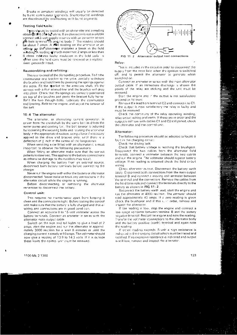
a
Breaks i n a rma tu re w ind ings w i l l u sua l l y be de tec tedby bu rn t commuta to r s . egmen ts . sho r t c i r cu i t ed w ind ingsa re d r sco lou red py ove ihea t i ng w i t h bu rn t segmen ts .
T e s t i n g f i e l d t o i l s :
T@se s i 6ou ld be t es ted w i t h an ohmmete r and a r ead ingob ta i n f t d 6 .O t r 6J ohms l f an ohmmete r i s no t ava i l ab l econnec t ad 2 - vo l t supp l y i n se r i es w i t h an ammete r ac ross
3 t f o t i e tO t e rm 'na lq t anq the body 7 The read ing shou ld6e abou t 2 amps . A f o r ead ing on t he ammete r o r anin f i n r y gp t hdohmm4er i nd i ca tes a b reak i n t he f i e l dwk rd ingYA read ing q [ much more t han 2 amps o r l ess t han6 ohms i ndaa tes f au l t y i nsu la t i on I n t he f i e l d co i l s . I ne. f ther case the f ie ld coi ls must be renewed or a replacement generat6r f i t ted.
R e a s s e m b l i n g a n d r e f i t t i n g :
Th i s i s a r eve rsa l o f t he d i sman t l i ng p rocedu re . To f i t t heco rnmu ta to r end b racke t t o t he yoke , pa r t i a l l y w i t hd rawthe b rushes and ho ld t hem by p ress ing t he sp r i ngs aga tns tt he s i des . F i t t he qacke t t o t he a rma tu re sha f t . l i f t t hesp r rngs w i t h a t h i n sc rewd r i ve r and t he b rushes w r l l d roprn to p l ace . Check t ha t t he sp i l ngs a re co r rec t l y pos i t i oned
on t op o f t he b rushes and p ress t he b racke t f u l l y home .Re f i t t he two t hough bo l t s . l . ub r i ca te t he commuta to rend bea r i ng . Re f i t t o t he eng ine , and ad jus t t he t ens ion o ft he be l t .
1 0 : 4 T h e a l t e r n a t o r
The a l t e rna to r . o r a l l e r r t a l i ng cu i l en t gene ra to r . i sd r i ven f r om the c ranksha f t bv t he same be l t as d r i ves t hewa te r pump and coo l i ng f an . The be l t t ens ion i s adJUStedby l oosen ing t he secu r i ng bo l t s and ro ta t i ng t he a l t e rna to rbody i n t he app rop r i a te d i r ec t i on , us i ng a l eve r i f necessa ryapp l i ed t o t he d r i ve end b racke t on l y , un t i l t he re i s ade f l ec t i on o f i i n ch rn t he cen t re o f t he l onges t r un
When se rv i c i ng a ca r f i t t ed w i t h an a l t e rna to r t t i s mos timpo r tan t t o obse rve t he f o l l ow ing p recau t i ons :
When f i t t i ng an a l t e rna to r make su re t ha t t he eo r rec tpo la r i t y i s obse rved . Th i s app l i es t o t he ba t t e r y connec t i onsas otherwise damage to the rect i f iers may resul t .
When cha rg i ng t he ba t t e r y f r om an ex te rna l sou rce ,d i sconnec t bo th ba t t e r y t e rm ina l s be fo re connec t i ng t hecha rge r .
Neve r r un t he eng ine w j t h e r t he r t he ba t t e r y o r a l t e rna to rd i sconnec ted . Neve r make o r b reak any connec t i ons i n t hea l t e rna to r c i r cu i t wh i l e t he eng ine i s r unn rng .
Be fo re d i sconnec t i ng o r r emov ing t he a l t e rna to rremember t o d i sconnec t t he ba t t e r y .
Con t ro l un i t :
Th i s r equ i r es no ma in tenance apa r t f r om keep ing i tc l ean and t he connec t i ons t i gh t . Be fo re t es t i ng t he con t ro lun i t make su re t ha t t he ba t t e r y i s f u l l y cha rged and t ha t a l lw i r i ng and connec t i ons a re i n good cond i t i on .
Connec t an accu ra te 0 t o 15 -vo l t vo l tme te r ac ross t heba t t e r y t e rm ina l s . Connec t an ammete r i n se r i es w i t h t hea l t e rna to r ma in ou tpu t cab le
Sw i t ch on t he s i de and t a i l l r gh t s t o g i ve a l oad o f 2amps , s t a r t t he eng ine and run t he a l t e rna to r a t app rox ima te l y 3000 rev /m in f o r a l eas t 8 m inu tes o r un t i l t hecha rg ing cu r ren t i s s t eady a t 1 0 a mps . The vo l tme te r shou l dnow g i ve a r ead ing o f 13 .9 t o 14 .3 vo l t s . l f i t i s ou t s i dethese l im i t s t he con t ro l un i t mus t be renewed .
1 1 0 0 M k 2 1 3 0 0
F IG 11 : 2 A l t e rna to r ou tpu t t es t connec t rons
R e l a v :
Th i s r s i nc l uded i n t he c r r cu r t i n o rde r t o d i sconnec t t hesupp l y f r om the ro to r f i e l d when t he i gn i t i on i s sw i t chedo f f , and t o pe rm i t t he a l t e rna to r t o gene ra te whensw i t ched on .
Connec t an ammete r i n se r i es w i t h t he ma in a l t e rna to rou tpu t cab le . l f an immed ia te d i scha rge i s shown t hepo in t s o f t he re l ay a re s t i c k i ng and t he un i t mus t berenewed .
S ta r t t he eng ine and i f t he ou tpu t i s no t sa t i s f ac to r yp roceed as f o l l ows :
Remove t he l eac i f r om te rm ina l C2 and connec t i t t o C1 .l f t he ou tpu t i s now sa t i s f ac to r y t he re l ay i s f au l t y andmus t be renewed .
Check t he con t i nu i t y o f t he re l ay ope ra t t ng w ind ing ,re l ay c i r cu i t w i r r ng and ea r t h . l f t hese a re i n o rde r and t heou tpu t i s s t i l l l ow w i t h cab les C1 and C2 s t i l l j o i ned , checkthe a l t e rna to r and t he con t ro l un r t .
A l t e r n a t o r :
The f o l l ow ing p rocedu re shou ld be adop ted t o l oca te afau l t i n t he cha rg i ng c i r cu i t :
Check t he d r i v i ng be l t .Check t ha t ba t t e r y vo l t age i s r each ing t he b rushgea r .
D i sconnec t t he two cab les f r om the a l t e rna to r f i e l dt e rmrna l s . connec t a vo l tme te r be tween t he two cab lesand run t he eng ine . The vo l tme te r shou ld r eg i s t e r ba t t e r yvo l t age . l f no r ead ing i s ob ta i ned check t he f i e l d c i r cu i tw i r i n g .
Check a l t e rna to r ou tpu t . D i sconnec t t he ba t t e r y ea r t hcab le . D i sconnec t bo th connec t i ons f r om the ma in ou tpu tt e rm ina l B and connec t a mov ing co i l ammete r be tween' t he
t e rm ina l and t he connec to r s . Remove t he cab les f r omthe f i e l d t e rm ina l s and connec t t he t e rm ina l s d i r ec t l y t o t heba t t e r y as shown i n F IG 11 : 2 .
Reconnec t t he ba t l e r y ea r t h l ead , s t a r t t he eng rne andrun t he a l t e rna to r a t 4000 rev /m in . The ammete r shou ldread app rox ima te l y 40 amps . l f a ze ro r ead ing r s g t venc h e c k t h e b r u s h g e a r a n d i f t h i s r : ; , r ' o r d e r , r e m o v e a n dinspec t t he a l t e rna to r .
l f t he r ead ing i s l ow , s t op t he eng ine and connec t al ow- range vo l tme te r be tween t e rm ina l B and t he ba t t e r ynega t i ve t e rm ina l . Res ta r t t he eng ine and no te t he read ing .T rans fe r t he vo l tme te r connec t i ons t o t he a l t e rna to r bodyand t he ba t t e r y pos i t i ve ( ea r t h ) t e rm ina l and aga in no tethe read ing .
l f e i t he r r ead ing exceeds . 5 - vo l t a h i gh res i s t ance i si nd i ca ted i n t he cha rg i ng c i r cu i t wh i ch mus t be t r aced andrec t i f i ed . l f no excess i ve res i s t ance t s i nd i ca ted and ou tpu ti s s t i l l l ow , r emove and j nspec t t he a l t e rna to r .
123
o

24
l 4
@o cE@
@@@
27 zi rsF I G 1 1 : 3 C o m p o n e n t s o f t h e a l t e r n a t o r
K e y t o F i g 1 1 : 3 1 S h a f l n u t 2 S p r i n g w a s h e r 3 K e y 4 T h r o u g h - b o l t 5 D i s l a n c e c o l l a r 6 D r i v e e n d b r a c k e t7 J u m p r n g s h r o u d 8 R o t o r ( f i e l d ) w i n d i n g 9 S l i p r i n g s 1 0 S t a t o r l a m i n a t i o n s 1 1 S t a t o r u r i n d i n g s 1 2 W a r n i n g l i g h tt e r m i n a l 1 3 O u t p u t t e r m i n a l 1 4 F r e l d t e r m i n a l b l a d e 1 5 O u t p u t t e r m i n a l p l a s l i c s t r i p 1 6 T e r m i n a l b l a d e r e t a i n i n g t o n g u e1 7 B r u s h
' 1 8 R o l o r 1 9 B e a r r n g c i r c l i p 2 0 B e a r r n g r e t a i n i n g p l a t e 2 1 B a l l b e a r i n g 2 2 O - r i n g o i l s e a l 2 3 O r i n g
r e t a i n i n g w a s h e r 2 4 F a n 2 5 B r u s h b o x 2 6 H e a t s i n k a s s e m b l i e s 2 7 S l i p r i n g e n d c o v e r
\t 3
f,,'26
t 7
Remov ing t he a l t e rna to r :
D i sconnec t t he ba t t e r y and remove t he cab les f r om thea l t e rna to r . S l acken t he secu r i ng bo l t s , push t he a l t e rna to rt owa rds t he eng rne and remove t he be l t . Remove t hebol ts and l i f t of f the al ternator .
I n s p e c t i o n :
Check the length of the carbon brushes and renew anyworn below 1f inch. Push the new brush assembly into
the ho lde r un t i l t he t ongue reg i s t e r s t hen l eve r i t up r no rde r t o r e ta i n t he b rush .
Check t ha t t he b rushes a re mov ing f r ee l y i n t he i rho lde rs , and i f necessa ry c l ean o r po l i sh w i t h a smoo thf i l e
The su r f aces o f t he s l i p r i ngs shou ld be smoo th andc lean . C lean w i t h a pe t ro l mo i s tened c l o th o r ve r y f i neglasspaper i f necessary. Do not at tempt to machine thes l i p r i n g s .
D i s m a n t l i n g ( s e e F i g 1 1 : 3 ) :
Remove t he sha f t nu t 1 and de tach t he d r i ve pu l l ey , f an24 and key 3 f rom the armature shaf t , tak ing great care tomark al l parts c lear ly to ensure correct reassembly.
Remove t he t h ree t h rough -bo l t s 4 and de tach t he d r i veend bracket 6 and rotor 18. The bracket and rotor neednot be separated unless the bear ing requires at tent ion.Remove the brushbox 25 at ter removing the outputt e rm ina l and t he re ta i n i ng sc rews .
Remove t he wa rn ing l i gh t t e rm ina l nu t 1 2 and t he hea ts i nk bo l t and w i t hd raw the s ta to r 10 and hea t s i nk 26 f r omthe s l i p r i ng end b racke t 27 . C lose t he re ta i n i ng t ongues'1
6 on the brush terminal b lades and wi thdraw the terminalsf r om the b rushbox 25 .
-< l I
[:t \ i 'I \-,
F IG 11 : 4 Us ing an ohmmete r 1 o r ammete r 2 t o t es t t heres i s t ance o r t he cu r ren t f l ow o f t he f i e l d w ind ing
1 2 4
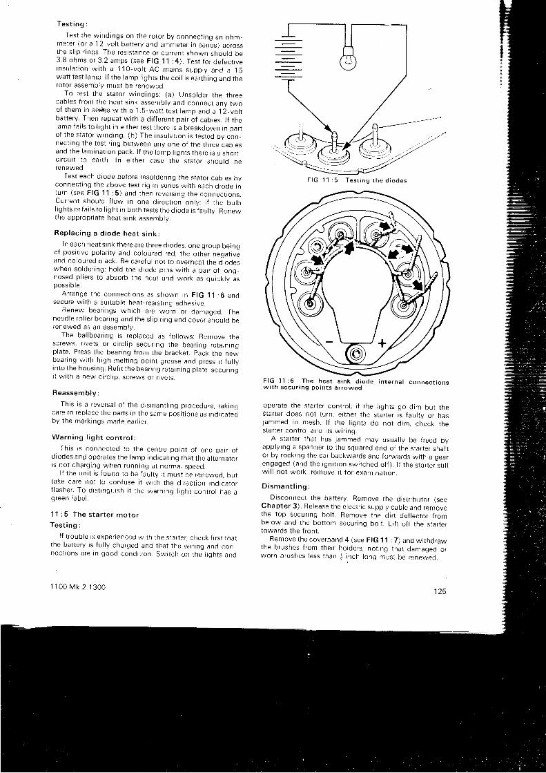
T e s t i n g :
Tes t t he w ind ings on t he ro to r by connec t i ng an ohm_mete r ( o r a 12 vo l t ba t t e r y and ammete r i n senes ) ac rossthe s l i p r i ngs . The res i s t ance o r cu r ren t shown shou ld be3 .8 ohms o r 3 .2 amps ( see F IG 11 : 4 ) . Tes t f o r de fec r i vei n s u l a t i o n w i t h a 1 1 0 - v o l t A C m a i n s s u p p l y a n d a 1 5wa t t t es t l amp . l f t he l amp l i gh t s t he co i l i s ea r t h i ng and t herotor assembly must be reneweo.
To t es t t he s ta to r w ind ings : ( a ) Unso lde r t he t h reecab les f r om the hea t s rnk assemb ly and connec t any twoo f t hem i n se r i r s w i t h a ' 1 . 5 -wa t t t es t l amp and a 12_vo l tbat tery. Then repeat wi th a d i f ferent pair of cables. l f thel amp fa i l s t o l i gh t i n e i t he r t es t t he re i s a b reakdown i n pa r ro f t he s ta to r w ind ing . ( b ) The i nsu la t i on i s t es ted bv con_nec t i ng t he t es t r i ng be tween any one o f t he t h ree cao tesand t he l am ina t i on pack . l f t he l amp l i gh t s t he re i s a sho r r_c l r cu t t t o ea r t h . I n e i t he r case t he s ta to r shou ld berenewed.
Test each diode before resolder ing the stator cables byconnec t i ng t he above t es t r i g i n se r i es w i t h each d i ode i nt u rn ( see F IG 11 : 5 ) and t hen reve rs i ng t he connec t i ons .Cu r ren t shou ld f l ow i n one d i r ec t i on on l y ; i f t he bu lbl i gh t s o r f a i l s t o l t gh t i n bo th t es t s t he d i ode i s f au l t y . Renewthe app rop r i a te hea t s i nk assemb ly .
R e p l a c i n g a d i o d e h e a t s i n k :
I n each heat sr n k there a re three d iodes, one grou p bei ngo f pos i t i ve po la r i t y and co lou red red , t he o the r neqa t t veand co lou red b l ack . Be ca re fu l no t t o ove rhea t t he d l ooeswhen so lde r i ng ; ho ld t he d i ode p i ns w i t h a pa i r o f l ong_nosed p l i e r s t o abso rb t he hea t and wo rk as qu i ck l y asposs i b l e .
A r r a n g e t h e c o n n e c t i o n s a s s h o w n i n F I G 1 1 : 6 a n osecu re w i t h a su i t ab le hea t - r es i s t i nq adhes i ve .
Renew bea r i ngs wh i ch u re *o i n o r damaqed Theneed le r o l l e r bea r i ng and t he s l r p r i ng end cove r shou lo oerenewed as an assembly.
The ba l l bea r i ng i s r ep laced as f o l l ows : Remove t hesc rews , r i ve t s o r c i r c l i p secu r i ng t he bea r i ng re ta i n rngplate. Press the bear ing f rom the bracket . pack the newbea r i ng w i t h h i gh me l t i ng po in t g rease and p ress i t f u r r yi n to t he hous ing . Re f i t t he bea r i ng re ta i n i ng p l a te , secu r i ngi t w i t h a new c i r c l i p . s c rews o r r i ve t s .
Reassemb ly :
Th i s i s a r eve rsa l o f t he d i sman t l i ng p rocedu re , t ak i ngca re t o r ep lace t he pa r t s i n t he same pos i t i ons as t nd i ca tedby t he mark i ngs made ea r l i e r
W a r n i n g l i g h t c o n t r o l :
Th i s i s connec ted t o t he cen t re po in t o f one pa i r o fd i odes and ope ra tes t he l amp i nd rca t rng t ha t t he a l t e rna to ri s no t cha rg i ng when runn ing a t no rma l speed
l f t he un i t i s f ound t o be f au l t y i t mus t be renewed , bu tt ake ca re no t t o con fuse i t w i t h t he d i r ec t i on i nd i ca to rf l ashe r . To d i s t i ngu i sh i t t he wa rn ing l i gh t con t ro l has ag reen l abe l .
11 : 5 The s ta r t e r mo to r
T e s t i n g :
l f t r oub le i s expe r i enced w i t h t he s ta r t e r , check f i r s t t ha tt he ba t t e r y i s f u l l y cha rged and t ha t t he w i i l ng and connec t rons a re r n good cond i t i on Sw i t ch on t he l i qh t s and
1 1 0 0 M k 2 1 3 0 0
F I G 1 1 : 5 T e s t i n g t h e d i o d e s
F I G 1 l : 6 T h e h e a t s i n k d i o d e i n t e r n a l c o n n e c t i o n sw i t h secu r i ng po in t s a r rowed
ope ra te t he s ta r t e r con t ro l ; i f t he I i gh t s go d im bu t t heS ta r t e r does no t t u rn , e i t he r t he s ta r t e r i s f au l t y o r hasjammed i n mesh . I f r he l i gh r s do no t d im , check t hes ta r t e r con t ro l and i t s w i r i ng .
A s ta r t e r t ha t has j ammed may usua l l y be f r eed byapp l y rng a spanne r t o t he squa red end o f t he s ta r t e r sha f tor by rocking the car backwards and forwards wi th a oearengaged (and t he rgn i t r on swr l ched o f f ) . l t t he s ta r t e r " s t i l lw r l l no t wo rk . r emove i t f o r exam ina t i on .
D i s m a n t l i n g :
_ D i sconnec t t he ba t t e r y . Remove t he d i s t r i bu to r ( seeChap te r 3 ) . Re lease t he e l ec t r i c supp l y cab le and removethe top secur ing bol t . Remove the di r t def lector f rombelow and the bot tom secur ing bol t . L i f t of f the star tertowards the f ront .
Remove t he cove rband 4 ( see F IG 11 : 7 ) and w i t hd rawthe b rushes f r om the r r ho lde rs , no t i ng t ha t damaqed o rwo rn b rushes l ess t han * i nch l ong mus t be renewed .
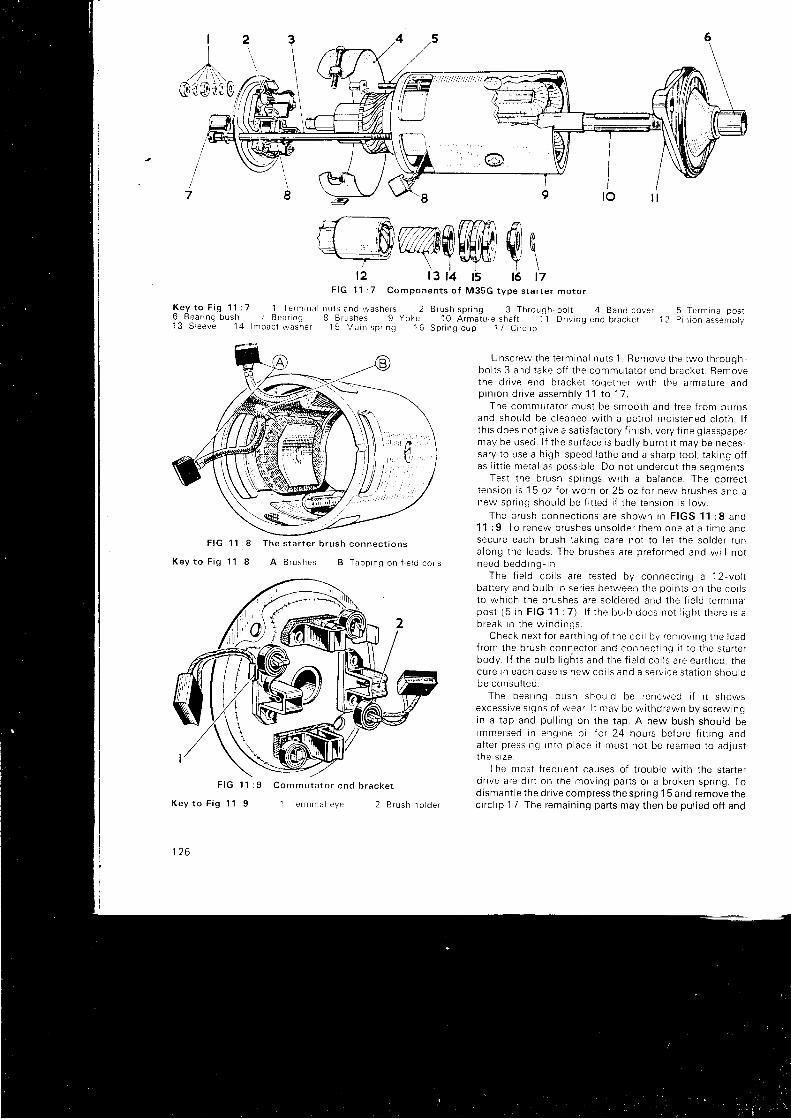
I
"Li;10\)o
2
K e y t o F i g 1 1 : 7 1 T e r m r n a n u l s a n d w a s h e r s 26 B e a r r n g b u s h ; B e d l n g 8 B r u q h e s 9 Y o , e1 3 S . e e v e 1 4 l m p a c t w d s h e r 1 5 M a , n : p r r n q 1 6
8
K e v t o F i g 1 1 : 9
t l o
1 T e r m r n a i e y e 2 B r u s h h o l d e r
flf- R rzAafiT\il fr\ ̂L-L-ty v/l/l#TJHrHrH HHl rti
\ lE/+'\5 Y \12 t3 14 t5 t6 t7
F I G 1 1 : 7 C o m p o n e n t s o f M 3 5 G t V p e s t a r t e r m o r o r
F I G 8 T h e s t a r t e r b r u s h c o n n e c t i o n s
K e y t o F i g 1 1 : 8 A B r u s h e s B T a p p r n g o n t i e l d c o i l s
B r u s h s p r i n g 3 T h r o u g h - b o l t 4 B a n d c o v e r 5 T e r m i n a l p o s t1 O A r m a t u r e s h a f t 1 1 D r r v i n g e n d b r a c k e t 1 2 P r n i o n a s s e m b l v
S p r i n g c u p 1 7 C i r c l r p
Unsc rew the t e rm ina l nu t s 1 . Remove t he two t h roughbo l t s 3 and t ake o f f t he commuta to r end b racke t . Removethe d r i ve end b racke t t oge the r w i t h t he a rma tu re andp i n i o n d r i v e a s s e m b l y 1 1 t o 1 7 ,
The commuta to r mus t be smoo th and f r ee f r om bu rnsand shou ld be c l eaned w i t h a pe t ro l mo i s tened c l o th . l ft h i s does no t g i ve a sa t i s f ac to r y f i n i sh , ve r y f r ne g l asspape rmay be used . l f t he su r f ace i s bad l y bu rn t i t may be neces -sa ry t o use a h i gh -speed l a t he and a sha rp t oo l , l a k i ng o f fas l i t t l e me ta l as poss ib l e . Do no t unde rcu t t he segmen ts .
Tes t t he b rush sp r i ngs w i t h a ba lance . The co r rec tt ens ion i s 15 oz l o r wo rn o r 25 oz fo r new b rushes and anew spnng shou ld be f i t t ed i f t he t ens ron i s l ow .
T h e b r u s h c o n n e c t i o n s a r e s h o w n i n F I G S 1 1 : 8 a n d1 1 : 9 . To renew b rushes unso lde r t hem one a t a t ime andsecu re each b rush t ak i ng ca re no t t o l e t t he so lde r r una long t he l eads . The b rushes a re p re fo rmed and w i l l no tn e e d b e d d i n g - i n .
The f i e l d co i l s a re t es ted by connec t i ng a 12 -vo l tba t t e r y and bu lb i n se r i es be tween t he po in t s on t he co i l st o wh i ch t he b rushes a re so lde red and t he f i e l d t e rm ina lpos t ( 5 i n F IG 11 : 7 ) . l f t he bu lb does no r l i gh t r he re r s ab r e a k i n t h e w i n d i n g s .
Check nex t f o r ea r t h i ng o f t he co i l by r emov lnq t he ! eadf rom the b rush connec to r and connec t i nq i t t o t he s ta r t e rbody . l f t he bu lb l i gh t s and t he f i e l d co i l s a re ea r t hed t hecu re i n each case i s new co i l s and a se rv i ce s ta t i on shou ldbe consu l t ed .
The bea r rng bush shou ld be renewed i f t t showsexcess i ve s i gns o f wea r . l t may be w i t hd rawn by sc rew ingin a t ap and pu l l i ng on t he t ap . A new bush shou ld beimmersed i n eng rne o i l t o r 24 hou rs be fo re f i t t i ng anda f t e r p ress rng rn to p l ace i t mus t no t be reamed t o ad lus tt he s r ze .
The n ros t f r equen t causes o f t r oub le w i t h t he s ta r t e rd r i ve a re d i r t on t he mov ing pa r t s o r a b roken sp r i ng . Todismant le the dr ive compress the spr ing 1 5 and remove thec i r c l i p 17 . The rema in i ng pa r t s may t hen be pu l l ed o f f and
F I G 1 1 : 9 C o m m u t a t o r e n d b r a c k e t
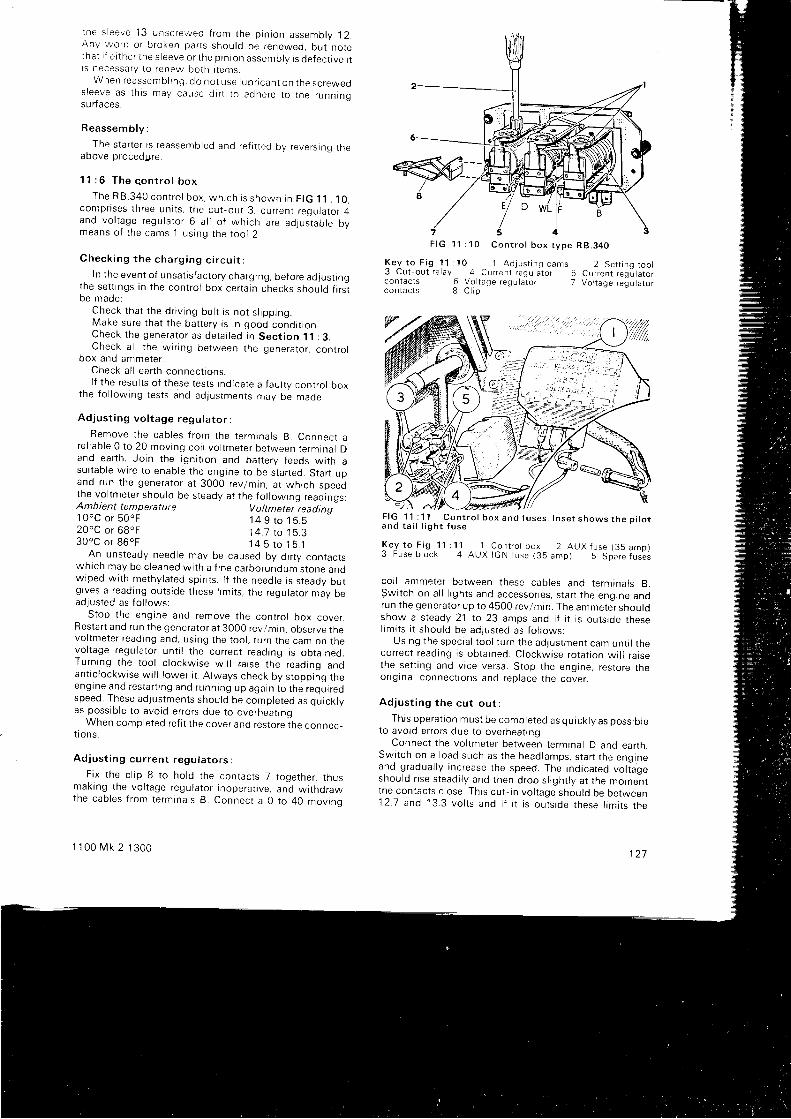
t he s l eeve 13 unsc rewed f r om the p i n i on assemb ly 12 .AnV wo rn o r b roken pa r t s shou ld be renewed , bu t no letna t i f e t t he r t he s l eeve o r t he p i n i on assemb ly i s de fec t i ve r trs necessary to renew both i tenrs.
When reassemb l rng , do no t use l ub r i can t on t he sc reweos leeve as t h i s may cause d i r t t o adhe re t o t he runn inos u r faces.
Reassemb ly :
The star ter is reassembled and ref i t ted by revers ing rneaDove procedUre.
11 : 6 The c .on t ro l box
The R B .340 con t ro l box , wh i ch i s shown i n F IG 11 : 10 .compnses t h ree un i t s , t he cu t_ou t 3 , cu r ren t r equ la to r 4and vo l t age regu la to r 6 a l l o f wh i ch a re ad jus tab le bymeans o f t he cams 1 us i ng t he t oo l 2 .
Check ing t he cha rg i ng c i r cu i t :
In the event of unsat is factory charging, before adjustrngthe set t ings in the contro l box certa in checks should f i rs tbe made :
Check t ha t t he d r i v i ng be l t i s no t s l i pp i ng .Make su re t ha t t he ba t t e r y i s i n good cond i t i on .Check t he gene ra to r as de ta i l ed i n Sec t i on 11 :3 .Check a l l t he w i r i ng be tween t he gene ra to r , con r ro l
oox and ammeter.Check a l l ea r l h connec t i ons .l f the resul ts of these tests indicate a faul ty contro l box
the f o l l ow ing t es t s and ad jus tmen ts may be made :
Ad jus t i ng vo l t age regu la to r :
Bemove t he cab les f r om the t e rm ina l s B . Connec t arel iable 0 to 20 moving coi l vol tmeter between terminal Dand earth. Join the igni t ion and bat tery feeds wl th asu i t ab le w i r e t o enab le t he eng ine t o be s ta r t ed . S ta r t uoand run t he gene ra to r a t 3000 rev lm in , a t wh i ch speedthe vol tmeter should be steady at the fo l lowing readings:Ambient temperature Voltmeter readino1 0 o C o r 5 0 o F 1 4 . 9 t o 1 5 . 520oC o r 6BoF30oC o r 86oF
K e y t o F i g 1 1 : 1 0 1 A d j u s t i n g c a m s 2 S e t r i n g t o o l3 C u t - o u t r e l a y 4 C u r r e n t r e g u l a t o r 5 C u r r e n t , e g - u l a t o rcontac ts 6 Vo l tage regu la to r 7 Vo l tage regu la to rc o n t a c t s 8 C l i p
14.1 to 15 .31 4 5 t o 1 5 . 1
An unsteady needle may be caused bv di r tv contacrswh i ch may be c l eaned w i t h a f i ne ca rbo rundum s tone andw iped w i t h me thy la ted sp i r i t s . l f t he need le i s s t eady ou tgives a reading outs ide these l imi ts, the regulator may beadjusted as fo l lows:
Stop the engine and remove the contro l box cover.Restar t and run the generator at 3000 rev. /min, observe thevol tmeter reading and, using the tool , turn the cam on thevot tage regulator unt i l the correct reading is obtaineo.Turning the tool c lockwise wi l l r ra ise the readinq anoan t i c l ockw i se w i l l l owe r i t . A lways check by s topp i i g t neeng ine and res ta r t i ng and runn ing up aga in t o t he requ i r edspeed. These adjustments should be completed as quic l<ryas possib le to avoid errors due to overheat ino.
When completed ref i t the cover and r . " r tor . ih. connec_t i ons.
Ad jus t i ng cu r ren t r egu la to r s :
F i x t he c l i p 8 r o ho ld r he con tac t s 7 t oge the r , t husmak ing t he vo l t age regu la to r i nope ra t i ve , and w i t hd rawthe cab les f r om te rm ina l s B . Connec t a 0 t o 40 mov rno
1 1 0 0 M k 2 1 3 0 0
F IG 1 1 : 1 1 Con t ro l box and f uses . I nse t shows t he p i l o ta n d t a i l l i g h t f u s e
Key t o F i g 11 : 11 1 Con t ro l box 2 AUX fuse (35 amp)3 Fuse b l ock 4 AUX IGN fuse (35 amp) b Spa re f uses
cor l ammeter between these cables and terminals B.$w i t ch on a l l l i gh t s and accesso r i es , s t a r t t he eng ine andrun t he gene ra to r up t o 4500 rev /m in . The ammete r shou ldshow a steady 21 to 23 amps and i f i t is outs ide thesel im r t s i t shou ld be ad jus ted as f o l l ows :
Us ing t he spec ia l t oo l t u rn t he ad jus tmen t cam un t i l t hecorrect readrng is obtained. Clockwise rotat ion wi l l rarsethe set t ing and v ice versa. Stop the engine. restore theo r i g i na l connec t i ons and rep lace t he cove r .
Ad jus t i ng t he cu t -ou t :
This operat ion must be completed as quickly as possioteto avoid errors due to overheat ing.
Connect the vol tmeter between terminal D and eartn.Sw i t ch on a l oad such as t he head lamps , s t a r t t he eng ineand gradual ly increase the speed. The indicated vol iageshou ld r i se s t ead i l y and t hen d rop s l i gh t l y a t t he momenrthe contacts c lose. This cut In vol tage should be between12 .7 and 13 .3 vo l t s and i f i t i s ou t s i de t hese l im r t s r ne
1 2 7
F I G 1 1 : 1 0 C o n t r o l b o x t y p e R B . 3 4 O
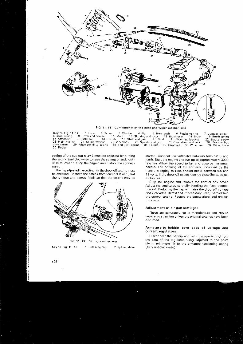
F I G 1 1 : 1 2 C o m p o n e n t s o f t h e h o r n a n d w i p e r m e c h a n i s m s
K e . y t o _ F i g 1 1 : 1 2 1 H o r n 2 S c r e w 3 W a s h e r 4 N u t 5 H o r n p u s h 6 R e t a i n i n g r i n g8 - M o t i l s p r i n g 9 C o v e r a n d c o n t a c t 1 1 M o t i i 1 2 S l i p r i n g a n d r o t o r 1 3 B r u s h g e a r t q g r u s n1 6 A r m a t u r e 1 7 F i e l d c o i l 1 8 S w i t c h 1 9 S h a f t a n d g e ; r 2 0 S t u d 2 1 M b u n r i n g b r a c k e t2 3 P l a i n w a s h e r 2 4 S p r i n g w a s h e r 2 5 W h e e l b o x 2 6 S p i n d l e a n d g e a r 2 7 C r o s s , h e a d a n d r a c kd r i v e - c a s i n g 2 9 W h e e l b o x d n v e c a s i n g 3 0 E n d d r r v e c a s i n g 3 1 F e r r u l e 3 2 G r o m m e l 3 3 W r p e r a r m3 5 R u b b e r
set t ing of the cut-out re lay 3 must be adjusted by turningthe set t ing tool c lockwise to ra ise the set t ing or ant ic lock-wise to lower i t . Stop the engine and restore the connec-t i ons .
Having ad. justed the cut t ing - in, the drop- of f set t ing mustbe checked. Remove the cables f rom ternr inal B and jo intthe igni t ion and bat tery feeds so that the engine may be
7 Contac t (upper )1 5 B r u s h s p r i n g
22 Bracket sc rew28 Molor to box
34 Wiper b lade
star ted. Connect the vol tmeter between terminal B andearth. star t the engine and run up to approximately 3000rev/min. Al low the speed to fa l l and observe the meterneedle. The openrng of the contacts, indicated by theneedle dropping to zero, should occur between 9.5 and11 vol ts. l f the drop-of f occurs outs ide these l imi ts, adjustas fo l lows:
Stop the engine and remove the contro l box cover.Adjust the set t ing by careful ly bending the f ixed contactbracket . Beducing the gap wi l l ra ise the drop-of f vol tageand v ice versa. Retest and, i f necessary, readjust to obtainthe correct set t ing. Restore the connect ions and replacethe cover.
Ad jus tmen t o f a i r gap se t t i ngs :
These are accurately set in manufacture and shouldrequire no at tent ion unless the or ig inal set t ings have beendistu rbed.
Armature-to-bobbin core gaps of vol tage andcu r ren t r egu la to r s :
Disconnect the bat tery and wi th the specia l tool turnthe cam of the regulator being adjusted to the pointg iv ing minimum l i f t to the armature tensioning spr ing( f u l l y an t i c l ockw i se ) .
F I G 1 1 : 1 3
K e y t o F i g 1 1 : 1 3
128
F i t t i n g a w i p e r a r m
i R e t a i n i n g c l i p 2 S p l i n e d d r i v e
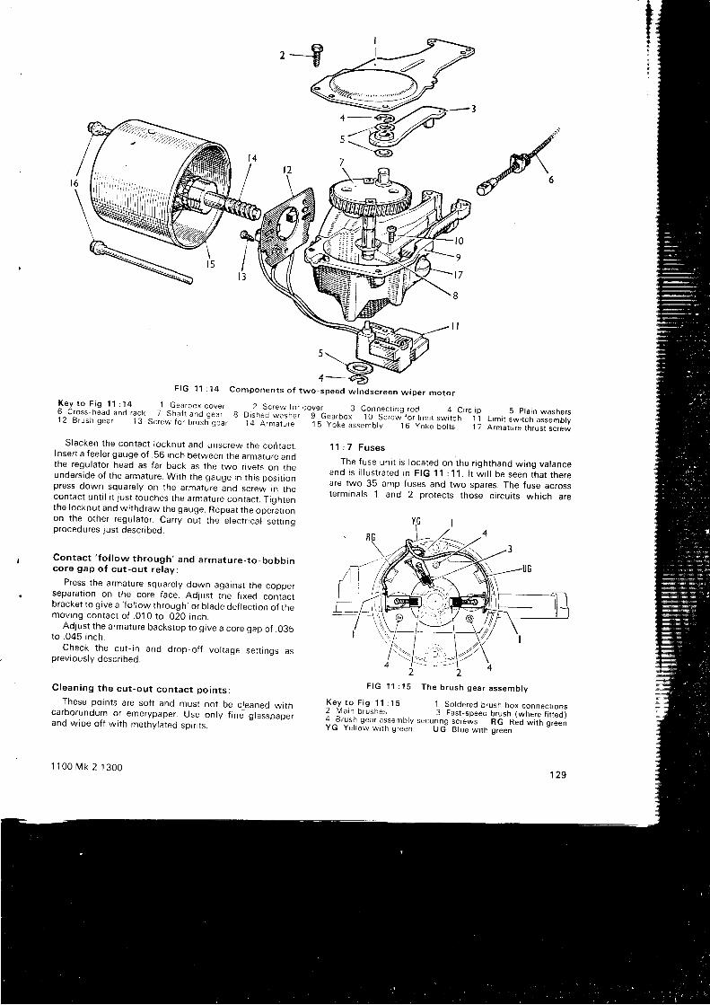
,-9
F I G 1 1 : 1 4 C o m p o n e n t s o f t w o - s p e e d w i n d s c r e e n w t p e r m o t o rK e y t o F i g 1 1 : 1 4 1 G e a r b o x c o v e r 2 s c r e w f o r c o v e r 3 c o n n e c t i n g _ r o d 4 c i r c l i p 5 p l a i n w a s h e r s6 c ross head and rack 7 Shaf t and gear e o iJJ* isner
- -9 -bearbox" j " t j " i? " * " ro ,
r im i r sw i tch - i I
L im i t iwr tcn assembry1 2 B r u s h g e a r 1 3 s c r e w f o r b r u s h " g e a r l t i ; ; ; ; ; , " t s y o k e a s s e m o r v ' - ' i o y o k e b o t l s 1 7 A r m a t u r e r h r u s t s c r e w
Slacken the contact locknut and unscrew the codtacr.Insert a feeler gauge of .56 inch between the armature andthe regulator head as far back as the two r ivets on theunderside of the armature. With the gauge in th is posi t ronpress down squarely on the armature and screw in thecontact unt i l i t just touches the armature contact . T iqhrenthe locknut and wi thdraw the gauge. Repeat the op" i r t ,onon t he o the r r egu la to r . Ca r r y ou t t he e l ec t r i ca l se t t i nqprocedures just descr ibed.
Con tac t ' f o l l ow t h rough ' and a rma tu re - t o_bobb inco re gap o f cu t - ou t r e l ay :
Press the armature squarely down agatnst the copperseparat ion on the core face. Adjust the f ixed contactbracket to g ive a
' fo l low through' or b lade def lect ion of the
mov rng con tac t o f . 01 0 t o . 020 i nch .Adjust the armature backstop to grve a core gap of .035
to . 045 i nch .Check the cut- in and drop-of f vol tage set t ings as
previously descr ibed.
C lean ing t he cu t -ou t con tac t po in t s :
These points are sof t and must not be c leaned wi thcarborundum or emerypaper. Use only f ine glasspaperand wipe of f wi th methylated spir i ts .
1 100 t \4k 2 1300
1 1 : 7 F u s e s
The fuse uni t is located on the r ighthand wing valanceand i s i l l u s t r a ted i n F IG 11 : 11 . l t w i l l be seen t ha t t he reare two 35-amp fuses and two spares. The fuse acrossterminals 1 and 2 protects those c i rcui ts which are
2 2F I G 1 1 : 1 5 T h e b r u s h g e a r a s s e m b l y
Ke-y_ to F ig 1 1 :1 5 1 So ldered brush box connect ions2 Main brushes 3 Fasr -speed br ; ;h i ; i ; ; ; ; i i " . ).4 ,^B. ,g r l
gear assembty secur rng screws RG Red ; i r i ; ; r " "Y u Y e l l o w w t t h g r e e n U G B l u e , a r t h q r e e n
129
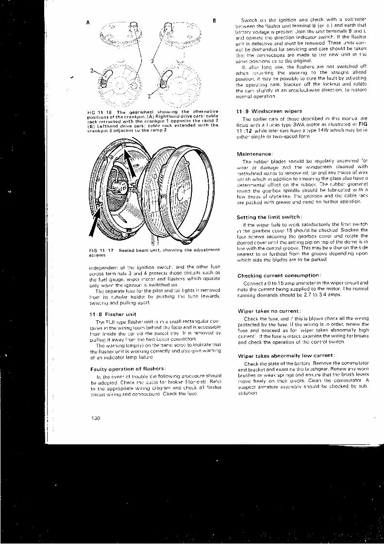
A
c r a n k p i n 3 a d j a c e n t t o t h e r a m P 2
F IG 11 : 17 Sea led beam un i t , show ing t he ad jus tmen tscrews
independen t o f t he i gn i t i on swr t ch , and t he o the r f use
across terminals 3 and 4 protects those c i rcui ts such as
the f ue l gauge , w ipe r mo to r and f l ashe rs wh i ch ope ra te
on l y when t he i gn i t i on i s sw i t ched on
The sepa ra te f use f o r t he p i l o t and t a i l l i Eh t s i s r emoved
f rom i t s t ubu la r ho lde r by push ing t he t ube i nwa rds ,
tw rs t i ng and Pu l l i ng aPa r t .
1 ' l : 8 F l a s h e r u n i t
The FL8 t ype f l ashe r un i t i s i n a sma l l r ec tangu la r con -
t a i ne r i n t he w i r i ng l oom beh rnd t he f ac i a and i s access ib l e
f r om i ns i de t he ca r v i a t he pa rce l t r ay l t i s r emoved by
pu l l i ng i t away f r om the two Luca r connec to r s
The wa rn ing l amp(s ) on t he pane l se r ve t o i nd i ca te t ha t
t he f l a she r un i t i s wo rk tng co r rec t l y and a l so g i ve wa rn ing
o f an i nd i ca to r l amP fa i l u re .
Fau l t y ope ra t i on o f f l a she rs :
l r r t he even t o f t r oub le t he f o l l ow ing p rocedu re shou ld
be adop ted : Check t he bu lbs f o r b roken f i l amen ts Re fe r
t o t he app rop r i a te w i r i ng d i ag ram and check a l l f l a she t
c i r cu i t w i r i ng and connec t i ons . Check t he f use
1 3 0
Sw i t ch on t he t gn i t i on and check w i t h a vo l tme te r
be tween t he f l ashe r un i t t e rm ina l B (o r + ) and ea r t h t ha t
ba t l e r y vo l t age i s p resen t . Jo i n t he un i t t e rm ina l s B and L
and ope ra te t he d i r ec t i on i nd i ca to r sw i t ch . l f t he f l ashe r
un i t i s de fec t i ve and mus t be renewed These un i t s can -
no t be d i sman t l ed f o r se r v i c i ng and ca re shou ld be t aken
tha t t he connec t i ons a re made t o t he new un i t i n t he
same pos i t i ons as t o t he o r i g i na l .l f , af ter long use, the f lashers are not swi tched of f
when re tu rn i ng t he s tee r i ng t o t he s t r a i gh t aheadpos i t i on , i t may be poss rb l e t o cu re t he f au l t by ad jus t i ng
the ope ra t i ng cam. S lacken o f f t he l ocknu t and ro ta te
the cam s l i gh t l y i n an an t i c l ockw i se d i r ec t i on , t o r es to re
no rma l ope ra t t on .
11 : 9 W indsc reen w iPe rs
The ea r l i e r ca r s o f t hose desc r i bed i n t h i s manua l a re
f i t ted wi th a Lucas tvpe 3WA motor as i l lustrated in FIG
11 : 12 , wh i l e l a t e r ca r s have a t ype 14W wh i ch may be i n
e i t he r s i ng le o r two -speed f o rm .
M a i n t e n a n c e :
The rubbe r b l ades shou ld be regu la r l y exam ined f o r
wea r o r damage and t he w indsc reen c l eaned w l t h
methvlated spir i ts to remove oi l , tar and any t races of wax
po l i sh wh i ch i n add i t i on t o smea r i ng t he g l ass a l so have a
de te r imen ta l e f f ec t on t he rubbe r . The rubbe r g rommet
round t he gea rbox sp ind le shou ld be l ub r i ca ted w i t h a
few d rops o f g l yce r i ne . The gea rbox and t he cab le r ack
are packed wi th grease and need no fur ther at tent lon
Se t t i ng t he l im i t sw i t ch :
l f t he w ipe r f a i l s t o wo rk sa t i s f ac to r i l y t he l im i t sw i t ch
i n t he gea rbox cove r 18 shou ld be checked S lacken t he
four screws secur ing the gearbox cover and rotate the
domed cove r un t i l t he se t t i ng p i p on t op o f t he dome i s i n
l i ne w i t h t he cen t ra l g roove . Th i s may be e i t he r on t he s i de
nearest to or fur thest f rom the groove depending upon
wh i ch s i de t he b l ades a re t o be pa rked
Check ing cu r ren t consumPt i on :
Connec t a 0 t o 1 5 amp ammete r i n t he w ipe r c i r cu i t and
no te t he cu r ren t be ing supp l i ed t o t he mo to r ' The no rma l
runn ing demands shou ld be 2 .7 t o 3 4 amps .
W ioe r t akes no cu r ren t :
Check t he f use , and i f t h i s i s b l own check a l l t he w i r i ngprotected by the fuse. l f the wir ing is in order, renew thefuse and p roceed as f o r
'w i pe r t akes abno rma l l y h i gh
cu r ren t ' l f t he f use r s i n t ac t , exam ine t he w i r i ng f o r b reaks
and check the operat ion of the contro l swi tch.
W ipe r t akes abno rma l l y l ow cu r ren t :
check the state of the bat tery. Remove the commutator
end b racke t and exam ine t he b rushgea r ' Renew any wo rn
b rushes o r weak sp r i ngs and ensu re t ha t t he b rush l eve rs
move f r ee l y on t he l r p i vo t s . C lean t he commuta to r ' A
suspec t a rma tu re assemb ly shou ld be checked by sub -
s t i t u t r on .
/' '':_-h
'a!?ain-, 1 -
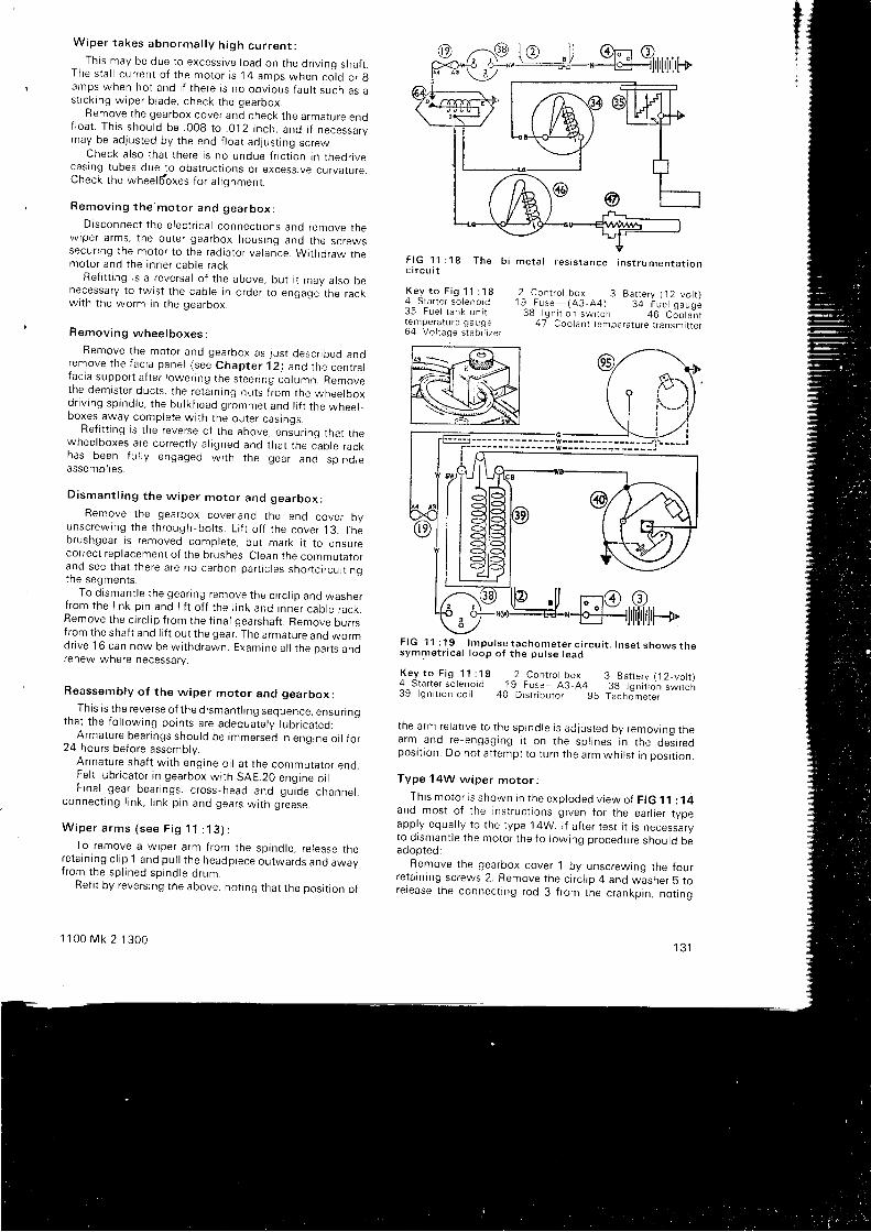
Wipe r t akes abno rma l l y h i gh cu r ren t :Th i s may be due t o excess i ve l oad on t he d r r v i nq sha f t .
The s ta l l cu r ren t o f t he mo to r i s 14 amps when co ]d o r gamps when ho t and i f t he re i s no obv ious f au l t such as as t i c k i ng w ipe r b l ade , check t he gea rbox .
Remove the gearbox cover and check the armature enof l oa t . Th i s shou ld be .008 t o .012 i nch , and i f necessa rymay be adjusted by the end f loat adjust ing screw.
Check a l so t ha t t he re i s no undue f r i c t i on i n t hednvecasing tubes due - to obstruct ions or excessive curvarure.Check the wheel6 'oxes for a l ignment.
Remov ing t he 'mo to r and gea rbox :
D i sconnec t t he e l ec t r i ca l connec t i ons and remove t hew ipe r a rms , t he ou te r gea rbox hous ing and t he sc rewssecur ing the motor to the radiator valance. Withdraw themo to r and t he i nne r cab le r ack .
Ref i t t ing is a reversal of the above, but i t may also benecessary to twtst the cable in order to engage the rackw i t h t he wo rm i n t he gea rbox .
Remov ing whee lboxes .
Remove t he mo to r and gea rbox as j us t desc r i bed anoremove t he f ac i a pane l ( see Chap te r 12 ) and t he cen t ra lf ac i a suppo r t a f t e r l owenng t he s tee r i ng co lumn . Removethe dem is te r duc t s , t he re ta i n i ng nu t s f r om the whee tboxd r i v i ng sp ind le , t he bu l khead g rommet and l i f t t he whee r -ooxes away complete wi th the outer casinqs.
Ref i t t ing is the reverse of the above, enJur inq that thewheelboxes are correct ly a l igned and that the c lb le rackhas been f u l l y engaged w i t h t he gea r and sp ind reassemb l i es .
D i sman t l i ng t he w ipe r mo to r and gea rbox :
Remove the gearbox coverand the end cover byunsc rew ing t he t h rough -bo l t s . L i f t o f f t he cove r 13 . Thebrushgear is removed complete, but mark i t to ensurecorrect replacement of the brushes. Clean the commutatorand see t ha t t he re a re no ca rbon pa r t i c l es sho r t c i r cu i t i nqthe segmen ts .
- To d i sman t l e t he gea r i ng remove t he c i r c l i p and washe rf r om the l i n k p i n and l i f t o f f t he l i n k and i nne r cab le r ack ,Remove the crrc l ip f rom the f inal gearshaf t . Remove burrsfrom the shaf t and l i f t out the gear. The armature and wormdr i ve 16 can now be w i t hd rawn . Exam ine a l l t he pa r t s anorenew where necessary.
Reassemb ly o f t he w ipe r mo to r and gea rbox :
This is the reverse of the d ismant l i ng sequence, ensur i ngtha t t he f o l l ow ing po in t s a re adequa te l v l ub r i ca ted :
^ _A rma tu re bea r i ngs shou ld be immersed i n eng ine o i l f o r24 hours before assembly.
A rma tu re sha f t w i t h eng ine o i l a t t he commuta to r end .Fe l t l ub r i ca to r i n gea rbox w i t h SAE .20 enq ine o i l .F i na l gea r bea r i ngs , c ross -head and gu - l de channe l ,
connec t t ng l i n k , l i n k p i n and gea rs w i t h g rease .
W i p e r a r m s ( s e e F i g 1 1 : 1 3 ) :
To remove a wiper arm from the spindle, re lease there ta rn i ng c l i p 1 and pu l l t he headp iece ou twa rds and awayf rom the sp l i ned sp ind le d rum.
Ref i t by revers ing the above, not ing that the posi t ion of
1 1 00 Mk 2 1 300
F I G 1 1 : 1 8 T h e b i - m e t a l r e s i s t a n c e i n s t r u m e n t a t a o nc i r c u i t
K e y t o F i g 1 1 : 1 8 2 C o n t r o l b o x 3 B a t t e r y ( 1 2 - v o l t )4 S t a r t e r s o i e n o i d 1 9 F u s e - ( 4 3 - 4 4 ) 3 + i u e l g a u g e3 5 F u e l t a n k u n i t 3 8 l g n i t i o n s w i t i h + O
- C J o i a n r
temp€ra ture gauge 47 Coo lan t tempera ture t ransmi r re r6 4 V o l t a g e s t a b i l i z e r
F I G 1 1 : 1 9 l m p u l s e t a c h o m e t e r c i r c u i t . I n s e t s h o w s t h es y m m e t r i c a l l o o p o f t h e p u l s e l e a d
K e y t o F i g 1 1 : 1 9 2 C o n r r o l b o x 3 B a t t e r y ( 1 2 _ v o t 1 )4 S t a n e r s o l e n o i d 1 9 F u s e - A 3 - A 4 3 g l q n r i r o n i w r t c n3 9 l g n i t i o n c o i r 4 0 D r s t n b u l o r 9 5 T a c h J m e r e r
- - '
the arm re ia t i ve to the sp ind le i s ad jus ted by remov ing thea r m a n d r e - e n g a g i n g i t o n t h e s p l i n e s i n t h e d e i i r e op o s i t i o n . D o n o t a t t e m p l t o t u r n t h e a r m w h i l s t i n p o s i t i o n .
Type 14W w ipe r mo to r :
Th i s mo to r i s shown i n t he exp loded v i ew o { F IG 11 : 14and mos t o f t he i ns t r uc l i ons g i ven f o r t he ea r l i e r t ypeapply equal ly to the type 14W. l f af ter test i t is necessarvto d ismant le the motor the fo l lowing procedure should beadooted:
Remove the gearbox cover 1 by unscrewing the fourretatn ing screws 2. Remove the c i rc l ip 4 and washer 5 torelease the connect ing rod 3 f rom the crankpin, notrng
+I
i
1 3 1
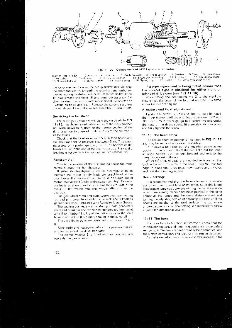
g'--Rt ,
t l - F l v\_ssreY,
F I G 1 1 : 2 0 C o m p o n e n t s o f M 3 5 J t y p e s t a r t e r m o t o r
K e y t o F i g 1 1 i 2 0 1 C o n r m u i a t o r e n d b f a c k e t 2 B u s h h o u s i n g 3 B r u s h . s p r r n g s 4 B r u s h e s 5 Y o k e ^ 6 P o l e s c r e w
7 p o l e s h o e g F r e t d c o r s 9 D r v e e n d b r a c k e t 1 0 B r " u s h b o x m o u l d i n g 1 1 A r m a l u r e 1 2 P i n i o n a n d b a r r e l
1 3 S c r e w e d s l e e v e l 4 B u f f e r r v a s h e r 1 5 M a r n s p r r n g 1 6 S p r r n g c u p 1 7 c i r c l i p 1 8 D r i v e e n d b r a c k e t b o l t
t he l owe r washe r . Remove t he c i r c l r p and washe r secu r l ng
the sha f t and gea r 7 . Smoo th t he gea rsha f t and w i t hd raw
the gea r no t i ng t he d r shed washe r 8 . Unsc re rn r t he two bo l t s
1 6 a n d r e m o v e t h e y o k e 1 5 a n d a r m a t u r e a s s e m b l y 1 4
a f t e r ma rk i ng t o ensu re co r rec t r ep lacemen t . C lean o f f any
me ta l l i c pa r t i c l es and dus t . Ren rove t he sc rews secu r i ng
the b rushgea r 12 and t he sw i t ch assemb ly 11 and l i f t o f f
S e r v i c i n g t h e b r u s h e s :
The b rushgea r assemb ly , wh i ch i s shown c l ea r l y i n F IG
11 : 15 , mus t be renewed be to re e i t he r o f t he ma in b rushesare worn down to - f , inch, or the narrow sect ion of the
th i r d b rush on two -speed mode l s down t o t he f u l l w id th
o f t he b rushCheck t ha t t he b rushes move f r ee l y i r i t he i r boxes and
tha t t he b rush sp r i ng p ressu re i s be twee r r 5 and 7 oz when
measu red o r r a push - t ype gauge w i t h t he bo i t on . r o t t he
b rush l eve l w r t h t he end o f t he s l o t i n t he box Re r rew t he
b rushgea r assemb ly i s t he sp r i ngs a re no t sa t i s f ac to r y
Reassemb ly :
Th i s i s t he reve rse o f t he d r sman t l i ng sequence , w i t h
ca re f u l a t t en t t on t o t he f o l l ow tng :l f e i t he r t he b rushgea r o r sw i t ch assemb ly i s t o be
renewed t he mo to r supp l y l eads a re unso lde red a t t he
b rushboxes . l t a new sw i t ch i s t o be f i t t ed t o a s rng le - speed
mo to r r emove t he YG w i re a t t he sw i t ch t e rm ina l Reso lde r
t he l eads as shown and ensu re t ha t t hey a re w i t h i n t he
recess i n t he sw i t ch mou ld i ng when re f i t t i ng i t t o t he
gea rbox .The gea rwhee l t ee th and cam, wo rm gea r , connec t l ng
rod and p i n , c ross head s l i de , cab le r ack and whee lboxgea rwhee l s a re a l l l ub r i ca ted w i t h Ragos ine L i s t a te G rease
The bea r i ng bushes , a rma tu re sha { t j ou rna l s , gea rwhee l
sha f t and c rankp rn and whee lbox sp ind les a re l ub r i ca ted
w i t h She l l Tu rbo 41 o i l , and t he f e l t washe r i n t he yoke
bea r i ng shou ld be t ho rough l y soaked i n t he same o i l
The yoke f i x i ng bo l t s a re t i gh tened t o a t o rque o f 14 lb
fr.S lacken t he end f l oa t sc rew be fo re f i t t i ng a new a rma tu re ,
and ad lus t as w i l l be desc r i bed l a t e r '
The d i shed washe r B i s f i t t ed w i t h i t s concave s rde
towa rds t he gea rwhee l s .
l 5 z
l f a new gea rwhee l i s be ing f i t t ed ensu re t ha t
t he co r rec t t ype i s ob ta i ned f o r e i t he r r i gh t o r
l e f t h a n d d r i v e c a r s ( s e e F I G 1 1 : 1 6 ) .
When f i t t i ng t he connec t i ng rod 3 t o t he c rankp in
ensure that the larger of the two f lat washers 5 is f i t ted
unde r t he connec t l ng rod .
A rma tu re end f l oa t ad jus tmen t :
T i gh ten t he sc rew 17 un t i l end f l oa t i s Jus t e l im ina ted
then t u rn i t back un t i l t he end f l oa t i s be tween 002 and.008 i nch . Use a f ee le r gauge t o measu re t he gap unde r
the head o f t he t h rus t sc rew , f i t a su i t ab le sh im i n p l ace
and f u l l y t i gh ten t he sc rew
1 1 : 1 0 T h e h e a d l a m p s
The sea led beam head lamp i s i l l u s t r a ted i n F IG 11 : 17
and may be se rv i ced on l y as an assemb ly .To ren rove a un i t t ake ou t t he re ta i n i ng sc rew a t t he
bo t t om o f t he r rm and l i f t o f f t he r im . Take ou t t he i nne r
secunng sc rews , pu l l t he un i t f o rwa rd and re l ease t heth ree p rn socke l a1 t he rea r
When re f i t t i ng , engage t he mou lded reg i s t e r s on t he
back edge w i t h t he s l o t s i n t he she l l . P ress t he rea r t opedge i n p l ace f i r s t , t hen p ress downw 'a rds and i nwa rds
and re f i t t he r e ta i n i ng sc rews .
Beam se t t i ng :
I t i s r ecommended t ha t t he beams be se t a t a se r v i ce
stat ion wi th an opt ical type beam set ter , but i f th is is not
conven t i en t i t may be done by po in t i ng t he ca r a t a wa l l on
wh i ch two a im ing marks have been pa ln ted a t t he same
he igh t as t he l amps and t he same d l s t ance apa r t and
tu rn i ng t he ad jus t i ng sc rews o f one l amp a t a t ime un t i l t he
beams are paral le l to the road surface. The top screw
arrowed ad justs the vert ical set t ing, whi le the lower screw
ad jus t s l he d i r ec t i ona l se t t i ng .
1 1 : 1 1 T h e h o r n
l f a ho rn f a i l s t o f unc t i on sa t i s f ac to r i l y check t ha t t hew i r i ng , connec t i ons and moun t i ng bo l t s a re i n o rde r be fo reremov ing i t . The ho rn canno t no rma l l y be d i sman t l ed , andthe s lot ted centra l core and locknut must not be disturbed.
A smal l serrated screw is provided to take up wear in the
1 3 1 4 1 5 1 6l ff1rr{ h,n.^t .filrllr\ lla\ ., -tlvu,su],fllltu \y] ,
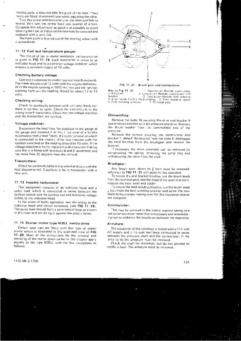
moving parts; t t does not a l ter the pi tch of the note. l f twoho rns a re f i t t ed , d i sconnec t one wh i l e ad jus t i ng t he o the r .
Tu rn t h i s sc rew an t i c l ockw i se un t i l t he ho rn l us t f a i l s t osound, then turn the screw back one quarter of a turn.Comp le te t h i s ad jus tmen t as qu i ck l y as poss ib l e t o avo rdblowing the fuse, or i f desired the fuse may be removed anorep laced w i t h a w i re l i n k .
The ho rn push i s l eve red ou t o f t he s tee r i nq whee l w i t ha screwdnver.
)11 : 12 Fue l and t empe ra tu re gauges
The c i r cu i t o f t he b i -me ta l r es i s t ance i ns t r umen ta t i oni s g i v e n i n F I G 1 1 : 1 8 . E a c h t r a n s m i t t e r i s w i r e d t o a nind i ca to r head and t o a common vo l t age s tab i l i ze r wh i chensu res a cons tan t supp l y o f 1 0 vo l t s .
Check ing ba t t e r y vo l t age :
Connec t a vo l tme te r t o con t ro l box t e rm ina l B and ea r t h .The me te r shou ld r ead 12 vo l t s w i t h t he eng ine s ta t i ona ry .W i th t he eng ine runn ing a t 1000 rev /m in and t he i qn i t i onwa rn ing l i gh t ou t t he read ing shou ld be abou t 1 i t o 13vot ls .
C h e c k i n g w i r i n g :
Check f o r con t i nu i t y be tween each un i t and check t ha tt he re i s no I eak t o ea r t h . Check f o r sho r t c i r cu i t s i n t hewr r i ng t o each t r ansm i t t e r . Check t ha t t he vo l t age s tab i l r ze rand the t ransmit ters are earthed.
Vo l t age s tab i l i ze r :
D i sconnec t t he l ead f r om the s tab i l i ze r t o t he gauge a tt h e g a u g e a n d c o n n e c t i t t o t h e ' l ' t e r m i n a l o f a S m i t h sAu tomo t i ve I ns t r umen t Tes te r , t he ea r t h t e rm tna l o f wh i chis connected to the chassis. Af ter two minutes wi th thergn i t i on sw i t ched on t he read ing shou ld be 10 vo l t s . l f t hevo l t age s tab i l i ze r i s f au l t y , r ep lace i t w i t h a new un i t mak ingsure that i t is f i t ted wi th terminals B and E upoermost andnot more than 20 degrees f rom the vert ical .
T ransm i t t e r s :
Check f o r con t i nu i t y be tween t e rm ina l and case w i t h t helead d i sconnec ted . Subs t i t u t e a f au l t y t r ansm i t t e r w i t h anew un i t .
1 1 : 1 3 l m p u l s e t a c h o m e t e r
Th i s equ ipmen t cons i s t s o f an i nd i ca to r head ano apu l se l ead , wh i ch i s connec ted i n se r res be tween t neign i t i on sw i t ch and t he i gn i t i on co i l and t r ansm i t s vo l t agepu l ses t o t he i nd i ca to r heao .
In the event of faul ty operat ion, test the wir ing to theind i ca to r head and c i r cu i t con r i nu i t y ( see F IG 11 : 1g ) .The pu l se l ead shou ld f o rm a symmet r i ca l l oop as showr rrn t he rnse t and no t be t i gh t aga ins t t he p l as t i c f o rms
11 : 14 S ta r t e r mo to r t ype M35J . i ne r t i a d r i ve
Certa in later cars are f i t ted wi th thts tvpe of star termo to r wh i ch i s i l l u s t r a ted i n t he exp loded v i ew o f F IG'1 1 :20 . Mos t o f t he i ns t r uc t i ons f o r t he remova l andse rv i c i ng o f t he s ta r t e r g r ven ea r l i e r i n t h i s c l r ap te r app l yequa l l y t o t he t ype M35J , w i t h t he f ew excep t i ons asfo l l ows .
1 1 0 0 M k 2 1 3 0 0
F i G 1 1 : 2 1 B r u s h g e a r a n d c o n n e c t i o n s
K e y t o F i g 1 1 i 2 1e n d b r a c k e t
1 S h o r t b r u s h f l e x t b l e , c o m m u r a r o r2 L o n g b r u s h - f l e x i b l e , c o m m u t a t o r e n d
b racke t 3 Long b rush - f l ex i b l e , f i e l d w ind ing4 Sho r t b rush f ex i b l e . f i e l d w rnd rng 5 yoke i nsu la t i on p rece6 F ie l d w ind ing j unc r on 7 Te rm ina l pos t
D i s m a n t l i n g :
Remove the bol ts '1
8 secur ing the dr ive end bracket 9and remove comp le te w t t h t he a rma tu re and d r i ve . Removethe thrust washer f rom the commutator end of thea rma tu re.
Remove t he sc rews secu r i ng t he commuta to r endb racke t 1 , de tach t he b racke t f r om the yoke 5 , d i sengagethe f i e l d b rushes f r om the b rushgea r and remove t hebracket .
l f necessary the dr ive assembly can be removed bycompress rng t he sp r i ng , r emov ing t he j ump r i ng andw i t hd raw ing t he d r i ve f r om the sha f t .
B r ushgea r :
Any b rush wo rn down t o t i n ch mus t be renewed ,re fe rence t o F IG 11 : 21 w i l l a ss i s t i n t h i s ope ra t i on .
To renew the end bracket brushes, cut the brush leadsf rom the terminal post . s lot the head of the post to accom-moda te t he new l eads and so lde r .
To renew the f i e l d w ind ing b rushes , cu t t he b rush l eads{ i nch f r om the f i e l d w ind ing j unc t i on and so lde r t he newleads t o t he s tumps mak ing su re t ha t t he i nsu la t i on s l eevesa re adequa te .
Commuta to r :
Th i s may be se rv i ced i n t he no rma l manne r t ak i ng ca renot to remove more metal than is necessary and remember-i ng no t t o unde rcu t t he i nsu la t i on be tween t he segmen ts .
A r m a t u r e :
The rnsu la t i on o f t he w ind ings i s t es ted w i t h a 1 ' 1 0 - vo l t
AC supp l y and a ' l
5 wa t t t es t l amp connec ted i n se r i esbe tween t he a rma tu re sha f t and t he commuta to r . l f t hel amp l i gh t s t he a rma tu re mus t be renewed .
Check the shaf t for d istor t ion, but do not at tempt torec t i f y a { au l t . The a rma tu re mus t be renewed .
/t--t-- -.-
F ie l d w ind ings :
Disconnect the windings f rom their r iveted connect ionw i t h t he yoke , and us i ng t he 110 -vo l t AC , 15 -wa t t t es tlamp between the yoke and each of the brushes in turn
check t he i nsu la t i on . l f t he l amp l i gh t s t he w ind ings mus tbe renewed.
Test for cont inui ty wi th a 1 2-vol t bat tery and bulb con-
nected between each of the f ie ld brushes and the yoke.
The lamp wi l l l ight i f the wir ing is sat is factory.
B e a r i n g s :l f there is excessive s ide play of the armature shaf t the
bearrngs must be renewed as fo l lows:
Commutator end bracket :Dr i l l out the r ivets secur ing the brushbox moulding and
remove the moulding, bear ing seal reta in ing plate and {e l t
washer seal . Screw in a j inch tap and pul l out the bear ingbush .
Dr ive end bracket :Support the bracket and press out the bush.New bushes may be pressed into posi t ion, using a
sui table mandrel , af ter a l lowing the bush to l ie immersedin engine oi l for 24 hours before f i t t ing.
Reassembly and ref i t t ing is the reverse of the dtsmant l -ing procedure.
11 : 15 A l t e rna to r t ype 16ACR
This is s imi lar to tvpe 1 ' l AC descr ibed ear l ier butincludes a bui l t - in vol tage regulator . Note that bat terypo la r i t y i s NEGATIVE EARTH.
1 1 : 1 6 F a u l t d i a g n o s i s
(a) Bat tery d ischarged1 Terminal connect ions loose or d l r ty2 Shorts in l ight ing c i rcui t3 Generator or a l ternator not charging4 Regulator or cut-out uni ts not funct ioning correct ly5 Batterv internal ly defect ive
(b ) I nsu f f i c i en t cha rg i ng cu r ren t1 Check 1 i n ( a )
2 D r i v i ng be l t s l i pp i ng
(c ) Ba t t e r y w i l l no t ho ld cha rge
1 Low electro lvte level2 Bat tery p lates sulPhated3 Electro lyte leakage f rom cracked case or top sealrng
compound4 Plate separators defect ive
(d) Bat tery overcharged1 Regulators need adjust ing
(e ) Gene ra to r ou tpu t l ow o r n i l1 Be l t b roken o r s l i pp i ng2 Regu la to r un i t ou t o f ad ius tmen t3 Worn bear ings, loose polepieces4 Commutator worn, burned or shorted5 Armature shaf t bent or worn6 I nsu la t i on p roud be tween commuta to r segmen ts7 B rushes s t i c k tng , sp r i ngs weak o r b roken8 F ie l d co i l w ind ings b roken , sho r t ed o r bu rned
1 3 4
( f ) A l t e rna to r ou tpu t l ow o r n i l
1 C h e c k 1 , 2 , 3 5 a n d 7 i n ( e )2 S l i p r i ng f ace d i r t y3 Open c i r cu i t i n d tode assemb ly4 Ro to r o r s t a to r w lnd ings b roken
(g ) S ta r t e r mo to r l acks power o r w i l l no t ope ra te
1 Ba t t e r y d i scha rged , l oose cab le connec t i ons2 S ta r t e r p i n i on t ammed i n f l ywhee l gea r
3 S ta r t e r sw i t ch f au l t y4 B rushes wo rn o r s t i c k i ng , l eads de tached o r sho r t t ng5 Commuta to r d i r t y o r wo rn6 Star ter shaf t bent7 Eng ine abno rma l l y s t i f f , pe rhaps due t o r ebo re
(h ) S ta r t e r mo to r r uns bu t does no t t u rn eng ine
1 P in i on s t i c k i ng on sc rewed s l eeve2 B roken t ee th on p i n i on o r f l ywhee l gea rs
( j ) No i sy s t a r t e r p i n i on when eng ine i s r unn ing
1 Res t ra i n i ng sp r i ng weak o r b roken
(k ) S ta r t e r mo to r i nope ra t i ve
1 C h e c k 1 a n d 4 i n ( g )2 A rma tu re o r f i e l d co i l s f au l tY
( t ) S ta r t e r mo to r r ough o r no i sY
1 Moun t i ng bo l t s l oose2 Damaged p i n i on o r f l ywhee l gea r t ee th
3 Ma in p i n i on sp r i ng b roken
(m) Lamps i nope ra t i ve o r e r ra t i c
1 Battery low, bulbs burned out2 Fau l t y ea r t h i ng o f l amps o r ba t t e r y3 Light ing swi tch faul ty, loose or broken connect tons
(n ) W ipe r mo to r s l ugg i sh , t ak i ng h i gh cu r ren t
1 Fau l t y a rma tu re2 Bea r i ngs ou t o f a l i gnmen t3 Commuta to r d i r t y o r sho r t c i r cu t t ed4 Whee lbox sp ind le b i nd ing , cab le r ack t i gh t i n ou te r
cas l ng5 Lack o f l ub r i ca t t on6 No end f loat to armature shaf t
( o ) W ipe r mo to r r uns bu t does no t d r i ve a rms
1 Whee lbox gea r and sp ind le wo rn2 Cab le r ack f au l t y3 Gearbox components worn
(p ) Fue l o r t empe ra tu re gauges do no t wo rk
1 Check w i r r ng f o r con t rnu i t y2 Vo l t age s tab i l i ze r f au l t ,3 Check i ns t r umen ts and t r ansm i t t e r s f o r con t i nu i t y
(q ) Fau l t y impu l se t ype t achome te r
1 Check w i r i ng and connec t i ons t o i nd i ca to r head
2 Pulse lead incorrect ly f i t ted

CHAPTER 12
THE BODYWORK
12 : 1 Remov ing doo r t r im1 2 : 2 S e r v i c i n g d o o r l o c k s12 : 3 The w indows and w ind ing mechan i sm12 :4 Luggage compar tmen t l ock
12 : 1 Remov ing doo r t r im
Aus t i n , Mo r r i s , Wo l se ley , R i l ey and MG ( see F ig1 2 : 1 ) :
Before the door t r im pad can be removed i t is f r rstnecessary to remove the window regulator handle, thei n te r i o r doo r hand le and t he doo r pu l l o r a rmres t . The twoformer r tems are re leased by removing the centre screwand spr ing washer; two screws are used to secure thea rmres t o r pu l l .
On two -doo r Mk 2 and 1300 mode l s t he an t i bu r s t l o c rremote contro l reta iner must be removed.
Remove the screws secur ing the door map pocket andlever the t r im pad away wi th a screwdr iver.
P r i ncess :
Remove t he doo r l ock and w indow regu la to r hand lesand t he d r i ve sc rews secu r i ng t he ch rome doo r pu l l t o t hearmrest . Remove the screws secur ing the armrest to themap pocket and remove the pocket . Remove the screwssecu r i ng t he t r im pane l and l eve r i t away f r om the doo r .Remove the dr ive screws and l i f t of f the door f in ishers.
On al l models ref i t t ing. is the reverse of removal .
1 1 0 0 M k 2 1 3 0 0
1 2 : 5 S e a t b e l t s12 : 6 Remov ing f ac i a , i n s t r umen ts and sw i t ches1 2 : 7 The hea te r1 2 : 8 A i r - c o n d i t i o n i n g
1 2 : 2 S e r v i c i n g d o o r l o c k s
E a r l y t y p e ( s e e F i g 1 2 : 2 ) :
To remove the lock i t is f i rs t necessary to remove theinne r doo r hand le , doo r pu l l and w indow regu la to r hand leas previously descr ibed. Remove the door t r im pad.Remove t he connec t i ng l i n k 5 f r om the l eve r 2 by r emov ingthe spr ing c l rp and wavy washer. Remove the setscrews gand remove t he l ock assemb ly .
To remove the outer door handle take out the screws 6.Ref i t t ing is the reverse of the removal sequence.
L a t e r t y p e ( s e e F i g 1 2 : 3 ) :
These an t i - bu rs t l o cks a re f i t t ed r o two doo r 1 100 Mk 2and 1 300 mode l s and may be seen i n pos i t i on i n F IG 12 : 4 .They { i t f lush wi th the door and can be locked f rom rneinside by pul l ing the safety latch rearwards.
To remove the lock, remove the window regulatorhandle, the armrest , the remote contro l reta iner, the t r impad and the grey door l iners. Release the c l ips 1 0, pul l of fl he two an t i - r a t t l e c l i p s 13 , r emove t he f ou r sc rews 14 anowithdraw the remote contro l assembly 7. Remove thecl ips 3 and 5 and wi thdraw the push but ton assemblv 6.
1 3 5
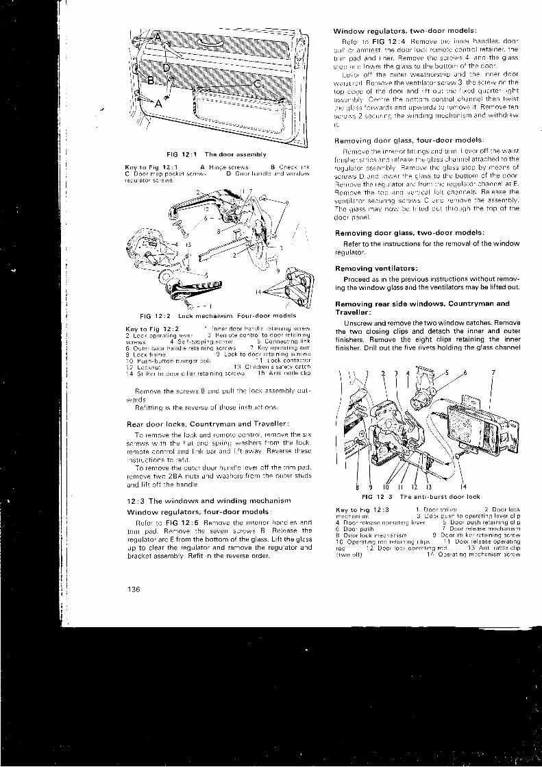
K e y t o F i g 1 2 : 1 A H i n g e s c r e w s B C h e c k l t n kC D o o r m a p p o c k e t s c r e w s D D o o r h a n d l e a n d w i n d o wr e g u l a t o r s c r e w s
F I G 1 2 : 2 L o c k m e c h a n i s m . F o u r - d o o r m o d e l s
Key t o F i g 12 :2 ' l I nne r doo r hand le r e ta i n i ng sc rew2 Lock ope ra t i ng l eve r 3 Remo te con t ro l 1o doo r r e ta i n l ngsc rews 4 Se l { - t app ing sc rew 5 Connec t i ng l i n k6 Ou te r doo r hand le r e ta i n i ng sc rews 7 Key ope ra t i ng a rm8 Lock f r ame 9 Lock t o doo r r e ta l n i ng sc rews10 Push -bu t t on p l unge r bo l t 11 Lock con tac to r12 Locknu t
' 1 3 Ch l d ren ' s sa te t y ca t ch1 4 S l r i ke r t o doo r p r l l a r r e ta i n i ng sc rews 1 5 An t i - r a t t l e c l r p
Remove t he sc rews B and pu l l t he l ock assemb ly ou t -wa rds .
Re f i t t i ng i s t he reve rse o f t hese i ns t r uc t l ons .
Rea r doo r l ocks , Coun t r y r ran and T rave l l e r :
To remove t he l ock and remo te con t ro l , r emove t he s l x
sc rews w i t h t he f l a t and sp r i ng washe rs f r om the l ock ,
r emo te con t ro l and l i n k ba r and l i f t away . Reve rse t heseins t r uc t i ons t o r e f t t .
To remove t he ou te r doo r hand le l eve r o t f t he t r im pad ,
remove two 2BA nu t s and washe rs f r om the ou te r s t uds
and l i f t o f f t he hand le .
1 2 : 3 T h e w i n d o w s a n d w i n d i n g m e c h a n i s m
Window regu la to r s , f ou r -doo r mode l s :
Re fe r t o F IG 1215 . Remove t he i n t e r i o r hand les andt f lm pad , Remove t he seven sc rews B . Re lease t heregulator arc E f rom the bot tom of the glass. Lr f t the glassup t o c l ea r t he regu la to r and remove t he regu la to r andbracket assembly. Ref i t in the reverse order.
l J C l
Window regu la to r s , two -doo r mode l s :
R e f e r t o F I G 1 2 : 4 R e m o v e t h e i n n e r h a n d l e s , d o o rpu l J o r a rmres t , t he doo r l ock r emo te con t ro l r e ta i ne r , t hetnm pad and l i ne r . Remove t he sc rews 4 , and t he g l ass
s top and l owe r t he g l ass t o t he bo t t om o f t he doo r .Leve r o f f t he ou te r wea the rs t r i p and t he t nne r doo r
wa rs t r a r l . Remove t he ven t i l a t o r sc rew 3 , t he sc rew on t he
toD edqe o f t he doo r and l i f t ou t t he f i xed qua r t e r - l i gh t
assen rb l v Cen t re t he bo t t om con t ro l channe l t hen tw i s tt he g l ass f o rwa rds and upwards t o r emove i t . Remove t en
sc re ' r vs 2 secu rLng t he w ind ing mechan i sm and w r thd raw
R e m o v i n g d o o r g l a s s . f o u r - d o o r m o d e l s :
Remove t he I n te f i o r f t t t t ngs and t r lm . Leve r o f f t he wa i s tf i n i she r s t r l ps end re i ease t he g l ass channe l a t t ached t o t heregu la to r assemb ly Remove t he g l ass s top by means o fsc rews D and l owe r t he g l ass t o t he bo t t om o f t he doo r .Remove t he regu la to r a r c f r on r t he regu la to l channe l a t E .Remove t he t op and ve r t t ca l f e l t channe l s . Re lease t heven t i l a t o r secunng sc rews C and remove t he assemb ly .The g l ass may now be l i f t ed ou t t h rough t he t op o f t hed o o r p a n e l .
Remov ing doo r g l ass , two -doo r mode l s :
Refer to the instruct ions for the removal of the windowregulator .
Remov ing ven t i l a t o r s :
Proceed as in the previous instruct ions wrthout remov-ing the window glass and the vent i lators may be l i f ted out .
Removing rear s ide windows. Countryman andT rave l l e r :
Unscrew and remove the two window catches. Removethe two c losing c l ips and detach the inner and outerf in ishers, Remove the eight c l ips reta in ing the innerf in isher. Dr i l l out the f ive r ivets hold ing the glass channel
I 9 l 0F I G 1 2 : 3
K e y t o F i g 1 2 : 3m e c h a n r s m
t t
T h e a n t i - b u r s t d o o r l o c k
1 D o o r s t i l k e f 2 D o o r l o c k3 D o o r p u s h t o o p e r a l i n g l e v e r c l i p
4 D o o r r e l e a s e o p e r a t i n g l e v e r 5 D c c r p u s h r e l a r n i n g c l i p
7
6 D o o r p u s h8 D o o r l o c k m e c h a n i s m
7 D o o r r e l e a s e m e c h a n i s m9 Door s t r i ker re ta in ing screw
1 0 O p e r a t i n g r o d r e t a i n n g c l i p s 1 1 D o o r r e l e a s e o p e r a t i n grod 12 Door lock opera t rng rod 1 3 Ant i ra l t le c l ip( two o f f ) 1 4 O p e r a t i n g m e c h a n i s m s c r e w
F I G 1 2 : 1 T h e d o o r a s s e m b l y

r e ta i ne r t o t he body . Remove t he assemb ly by l eve r i ng t heg lass channe l r e ta i ne r up and ou t f r om the bo t t om.
To remove t he g l ass f r om the assemb ly ca re fu l l y f l e xthe sp r i ng s tee l channe l r e ta i ne r and l i f t ou t t he c l ass .
When rep lac i ng t he w indow sea l i t I n t o t ne t odyape r tu re w i t h G las t i con Dum Dum pu t t y , pa r t No .91H .2727 , t ak i ng ca re no t t o sea l ove r t he wa te r ou t l e r s .
T w o - d o o r s a l o o n ( s e e F i g 1 2 : 6 ) :
Remove the screws secur ing the catch 6 to the bodyand open t he w i r i dow s l i gh t l y . G r i p t he t op andbo t t omf i rm l y and pu l l t he g l ass and f r ame ou t o f t he body rubbe rg laz i ng . Re f i t by r eve rs i ng t he above p rocedu re .
1 2 : 4 L u g g a g e c o m p a r t m e n t l o c k
R e f e r t o F I G 1 2 : 7 . O n n o a c c o u n t s h o u l d t h eluggage compar tmen t l i d be c l osed wh i l e t he l ockmechan i sm i s be ing removed o r r e f i t t ed .
Remove t he no t ched l ock i ng r i ng 1 and w i t hd raw thepush bu t t on assemb ly . Unhook t he connec t j ng l i n k 3 ,r emove t he sc rews 2 and w i t hd raw the ca t ch assemb ly .
Ref i t t ing is the reverse of the above.
1 2 : 5 S e a t b e l t s
The a t t achmen t po in t s and f i t t i ngs f o r t he sea t be l t s a reshown i n F IG 12 : 8 and t h i s d rag ram shou ld be used whenf i t t i ng
F i t t i ng t o cen t re p i l l a r :
The t op f i x i ng ho le may be beh ind t he t r im o r concea tedby a snap bu t t on . Cu t a ho le i n t he t nm to co inc i de w i t h
F I G 1 2 : 5
K e y t o F i g 1 2 : 5
D o o r i n t e r i o r . F o u r - d o o r m o d e l s
A D o o r l o c k r e m o t e c o n t r o l
1 D o o r l o c k r e m o t e c o n t r o l2 W i n d o w r e g u l a t o r a n d b r a c k e t s c f e w s 3 V e n t i l a t o r s c r e w
B W r n d o w r e g u l a t o r a n d b r a c k e t s c r e w s C V e n t i l a t o r s c r e wD D o o r s t o p s c r e w s E G l a s s r e g u l a t o r a r c
Key t o F i g 12 : 6 1 F rame assemb ly ( r ea r r i gh tha r ro /2 F rame assemb ly ( f r on t r r gh thand ) 3 G laz i ng rubbe r4 Sc rew 5 G lass 6 Ca tch assemb ly 7 R i ve i
t he ho le i n t he p i l l a r , no t rng t ha t on Vanden P las mode l sthe ho le i n t he ha rdboa rd l i ne r mus t a i so co inc i de w i t h t hep i l l a r h o l e .
F i t t he b racke t , a waved washe r and a shou lde redd i s tance p i ece ( t he sma l l e r d i ame te r o f wh i ch w i l l s l o tI n t he b racke t ) on a + i nch bo l t and sc rew the bo l t i n t othe ho le i n t he p i l l a r , mak ing su re t ha t no f ab r i c i n t e r f e resw i t h a me ta l t o me ta l con tac t be tween d i s t ance p i ece andp i l l a r ( s e e i n s e t 1 ) .
S i l l f i x i ng f o r s t a t i c be l t s ( see i nse t 2 ) :
Cu t t he ca rpe t ove r t he f i x rng ho le t o ensu re a me ta l t ome ta l con tac t . F i t t he b racke t , a waved washe r and ashou lde red d r s tance p i ece ( t he sma l l e r d i ame te r o f wh i chs lo t s i n t o t he b racke t ) on a 1 f i nch bo l t and sc rew i n to t heh o l e i n t h e s i l l .
II
7<la t
-'l '\., /
tii;, I-'ti[H I:llP6),r'[ i, . 4 2
I
F I G 1 2 : 4
K e y t o F i g 1 2 : 4
4 Door s top screws6 A n t i r a t t l e c l i p s
1 1 0 0 M k 2 1 3 0 0
5 D o o r g l a s s r e g u l a t o r a r c
3D o o r i n t e r i o r . T w o - d o o r m o d e l s
137
n,,/ iF I G 1 2 : 6 R e a r q u a r t e r l i g h t
'e4 =1
;, ;=.i\ : - , / ' l
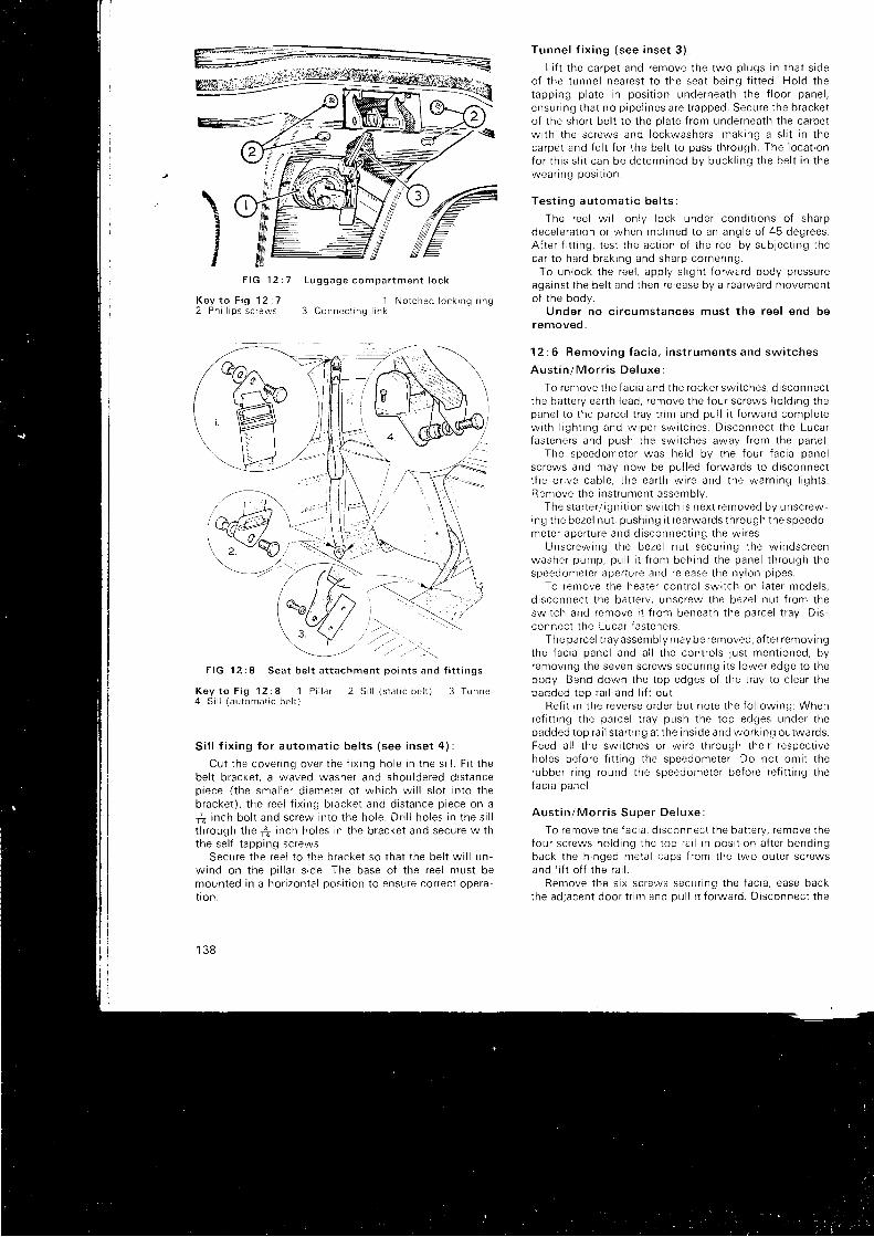
\ vIxII
IF I G ' 1 2 : 7 L u g g a g e c o m p a r t m e n t l o c k
K e y t o F i g 1 2 : 7 1 N o t c h e d l o c k i n g r r n g2 P h i l l i p s s c r e w s 3 C o n n e c t i n g l i n k
F I G 1 2 : 8 S e a t b e l t a t t a c h m e n t p o i n t s a n d f i t t i n g s
Key t o F i g 12 : 8 1 P i l l a r 2 S i l l ( s ra t i c be l r ) 3 Tunne l4 S i l l ( au toma t i c be l t )
S i l l f i x i ng f o r au toma t i c be l t s ( see i nse t 4 ) :
Cu t t he cove r i ng ove r t he f i x i ng ho le i n t he s i l l . F i t t hebe l t b racke t , a waved washe r and shou lde red d i s t ancep iece ( t he sma l l e r d i ame te r o f wh i ch w i l l s l o t i n t o t heb racke t ) , t he ree l f i x r ng b racke t and d i s t ance p i ece on a
r f i n ch bo l t and sc rew i n to t he ho le . D r i l l ho l es i n t he s i l lt h rough t he + i nch ho les i n t he b racke t and secu re w i t hthe se l f t app ing sc rews .
Secu re t he ree l t o t he b racke t so t ha t t he be l t w i l l un -w ind on t he p i l l a r s i de . The base o f t he ree l mus t bemoun ted i n a ho r i zon la l pos r t r on l o ensu re co r rec t ope ra -t i on .
1 3 8
Tunne l f i x i ng ( see i nse t 3 ) ;
L i f t t he ca rpe t and remove t he two p l ugs i n t ha t s i deo f t he t unne l nea res t t o t he sea t be ing f i t t ed . Ho ld t hetapp ing p l a te i n pos i t i on unde rnea th t he f l oo r pane l ,ensu r i ng t ha t no p i pe l i nes a re t r apped . Secu re t he b racke tof the short bel t to the plate f rom underneath the carpetw i t h t he sc rews and l ockwashe rs , mak ing a s l i t i n t heca rpe t and f e l t f o r t he be l t t o pass t h rough . The l oca t i onfo r t h i s s l i t can be de te rm ined by buck l i ng t he be l t i n t hewea r i ng pos i t i on .
Tes t i ng au toma t i c be l t s :
The ree l w i l l on l y l ock unde r cond i t i ons o f sha rpdece le ra t i on o r when i nc l i ned t o an ang le o f 45 deg rees .Af ter f i t t ing, test the act ion of the reel by sublect ing theca r t o ha rd b rak i ng and sha rp co rne r i ng .
To un lock t he ree l , app l y s l i gh t f o rwa rd body p ressu reaga ins t t he be l t and t hen re l ease by a r ea rwa rd movemen to f t he body .
Unde r no c i r cums tances mus t t he ree l end beremoved .
1 2 : 6 R e m o v i n g f a c i a , i n s t r u m e n t s a n d s w i t c h e s
A u s t i n / M o r r i s D e l u x e :
To remove t he f ac i a and t he rocke r sw i t ches . d i sconnec tt he ba t t e r y ea r t h l ead , r emove t he f ou r sc rews ho ld i ng t hepane l t o t he pa rce l t r ay t r im and pu l l i t f o rwa rd comp le tew i t h l i gh t i ng and w ipe r sw i t ches . D i sconnec t t he Luca rf as tene rs and push t he sw i t ches away f r om the pane l .
The speedome te r was he ld by t he f ou r f ac i a pane lsc rews and mav now be ou l l ed f o rwa rds t o d i sconnec tt he d r i ve cab le , t he ea r t h w i r e and t he wa rn ing l i gh t s .Remove t he i ns t r umen t assemb ly .
The s ta r t e r / i gn i t i on sw i t ch i s nex t r emoved by unsc rew-i ng t he beze l nu t , push ing i t r ea rwa rds t h rough t he speedo -me te r ape r t u re and d i sconnec t i ng t he w i res .
Unsc rew ing t he beze l nu t secu r i ng t he w indsc reenwashe r pump , pu l l i t f r om beh ind t he pane l t h rough t hespeedome te r ape r t u re and re l ease t he ny l on p rpes .
To remove t he hea te r con t ro l sw r t ch on l a t e r mode l s ,d i sconnec t t he ba t t e r y , unsc rew the beze l nu t f r om theswr t ch and remove i t f r om benea th t he oa rce l t r av . D i s -connec t t he Luca r f as tene rs .
The pa rcel t ray assembly may be removed, af ter removingthe f ac i a pane l and a l l t he con t ro l s Jus t men t i oned , byremoving the seven screws secur ing i ts lower edge to thebody. Bend down the top edges of the t ray to c lear thepadded t oD ra i l and l i f t ou t .
Re f i t i n t he reve rse o rde r bu t no te t he f o l l ow ing : Whenre f i t t i ng t he pa rce l t r ay push t he t op edges unde r t hepadded t op ra i l s t a r t i ng a t t he i ns i de and wo rk i ng ou twa rds .Feed a l l t he sw i t ches o r w i r e t h rough t he i r r espec t i veho les be fo re f i t t i ng t he speedome te r . Do no t om i t t herubbe r r i ng r ound t he speedome te r be fo re r e f i t t i ng t hefac i a pane l .
A u s t i n / M o r r i s S u p e r D e l u x e :
To remove t he f ac i a , d i sconnec t t he ba t t e r y , r emove t hefou r sc rews ho ld i ng t he t op ra i l r n pos i t i on a f t e r bend ingback t he h i nged me ta l caps f r om the two ou te r sc rewsand l i f t o f f t he r a i l .
Remove t he s i x sc rews secu r i ng t he f ac i a , ease backthe ad iacen t doo r t r im and pu l l i t f o rwa rd . D i sconnec t t he
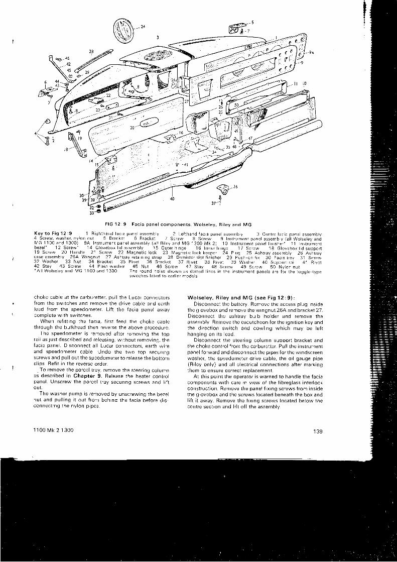
'B-4642456
F I G 1 2 : 9 F a c i a p a n e l c o m p o n e n t s . W o l s e l e y , R i l e y a n d M G
K e y t o F i g l 2 : 9 l R i g h t h a n d f a c i a p a n e l a s s e m b l y 2 L e f l h a n d f a c i a p a n e l a s s e m b l y 3 C e n t r e f a c i a p a n e l a s s e m b l y4 S c r e w , w a s h e r , n y l o n n u t 5 B r a c k e t 6 B r a c k e t 7 S c r e w 8 S c r e w 9 I n s t r u m e n t p a n e l a s s e m b l y ( a i l W o l s e l e y a n dM G 1 1 0 0 a n d 1 3 0 0 ) 9 A I n s t r u m e n t p a n e l a s s e m b l y ( a l l R i l e y a n d M G 1 3 0 0 M k 2 )
' l 0 I n s t r u m e n t p a n e l { i n i s h e r ' 1 1 I n s t r u m e n t
b e z e l - ' l 2 S c r e w - 1 4 G l - o v e b o x l i d a s s e m b l y 1 5 O u t e r h i n g e 1 6 I n n e r h i n g e 1 7 S c r e w 1 8 G l o v e b o x l i d s u p p o r t1 9 S c r e w 2 0 H a n d l e 2 1 S c r e w 2 2 M a g n e t i c l o c k 2 3 M a g n e t i c l o c k k e e p e r 2 4 P l u g 2 5 A s h t r a y a s s e m b l y 2 6 A s h i r a yc a s e a s s e m b l y 2 6 4 W i n g n u t 2 7 A s h t r a y r e t a i n i n g s t r a p 2 8 D e m i s t e r s l o t f i n i s h e r 2 9 P u s h , o n f i x 3 O F a c i a t r a y 3 1 S c r e w32 Washer 33 Nut 34 Bracket 35 R ive t 36 Bracket 37 R ive t 38 R ive t 39 Washer 40 Suooor t ra i l 41 B ive t42 Sray 43 Screw 44 P la in washer 45 Nut 46 Screw 47 Stay 48 Screw 49 Screw 50 Ny lon nu t- A l l W o l s e l e y a n d M G 1 1 0 0 a n d 1 3 0 0 T h e r o u n d h o l e s s h o w n a s d o t t e d l i n e s i n t h e i n s t r u m e n t p a n e l s a r e f o r t h e t o g g l e - t y p e
swi tches f i t ted to ear l ie r mode ls
choke cab le a t t he ca rbu fe t t e r , pu l l t he Luca r connec to r sf r om the sw i t ches and remove t he d r i ve cab le and ea r t hlead f rom the speedometer. Lt f t the facia panel awaycomolete wi th swi tches.
When ref i t t ing the facia, f i rs t feed the choke cabtethrough the bulkhead then reverse the above procedure.
The speedometer is removed af ter removing the topra r l as j us t desc r i bed and re l eas ing , w i t hou t r emov ing , t hefac i a pane l . D i sconnec t a l l Luca r connec to r s , ea r t h w i r eand speedome te r cab le . Undo t he two t op secu r i ngscrews and pul l out the speedometer to re lease the bot tomcl ips. Ref i t in the reverse order.
-To remove the parcel t ray, remove the steer ing columnas descr ibed in Chapter 9. Release the heater contro lpanel . Unscrew the parcel t ray secur ing screws and l i f tou t .
The washer pump is removed by unscrewing the bezelnu t and pu l l i ng i t ou t f r om beh ind t he f ac i a be fo re d i s -connec t i ng t he ny l on p i pes .
1 1 0 0 M k 2 1 3 0 0
W o l s e l e y , R i l e y a n d M G ( s e e F i g 1 2 : 9 ) :Disconnect the bat tery. Remove the access plug inside
the glovebox and remove the wingnut 264 and bracket 27.D i sconnec t t he ash t ray bu lb ho lde r and remove t heassembly. Remove the escutcheon for the igni t ion key andthe d i r ec t i on sw i t ch and cow l i ng wh i ch may be l e f thang ing on i t s l ead .
Disconnect the steer ing column support bracket andthe choke contro l f rom the carburet ter . Pul l the instrumentpanel forward and disconnect the pipes for the windscreenwashe r , t he speedome te r . d r i ve cab le , t he o i l gauge p i pe(R i l ey on l y ) and a l l e l ec t r i ca l connec t i ons a f t e r ma rk i ngthem to ensure correct replacement.
At th is point the operator is warned to handle the faciacomponents wi th care in v iew of the f ibreglass inter lockconstruct ion. Remove the panel f ix ing screws f rom insidethe glovebox and the screws located beneath the box anol i f t r t away. Remove the f ix ing screws located below thecentre sect ion and l i f t of f the assemblv.
1 3 9
-@
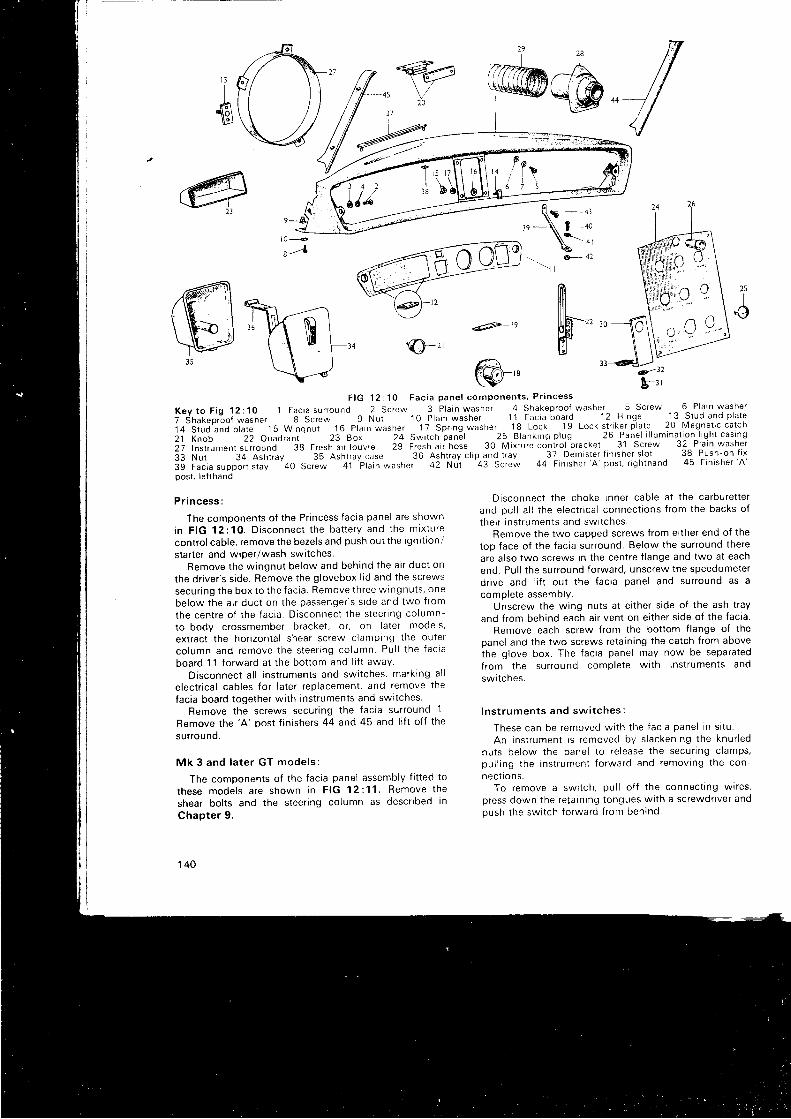
,A' i F( ))SV
ffimPr incess :
The comoonents of the Pr incess facia panel are shown
in F IG 12 :10 . D i sconnec t t he ba t t e r y and t he m ix tu re
contro l cable, remove the bezels and push out the igni t ion/
star ter and wiper/wash swi tches.Remove t he w ingnu t be low and beh ind t he a i r duc t on
the dr iver 's s ide. Remove the glovebox l id and the screws
secu r i ng t he box t o t he f ac i a . Remove t h ree w ingnu t s , one
below the ai r duct on the passenger 's s ide and two f rom
the cen t re o f t he f ac i a . D i sconnec t t he s l ee r i ng co lumn-
to-body crossmember bracket , or , on later models,
extract the hor izontal shear screw clamptng the outer
co lumn and remove t he s tee r i ng co lumn Pu l l t he f ac i a
board 11 forward at the bot tom and l t f t away.
Disconnect a l l instruments and swrtches, marking al l
e lectr ical cables for later replacement, and remove the
{acia board together wi th instruments and swi tches
Remove the screws secur ing the facia surround 1
Remove the 'A ' post f in ishers 44 and 45 and l i f t of f the
surrou nd.
Mk 3 and l a t e r GT mode l s :
The components of the facia panel assembly f i t ted to
these mode l s a re shown i n F IG 12 :11 . Remove t he
shear bol ts and the steer ing column as descr ibed in
Chapter 9.
1 4 0
@'F I G 1 2 : 1 0 F a c i a p a n e l c o m p o n e n t s , P r i n c e s s
K e y t o F i g 1 2 : 1 0 1 F a c i a s u r r o u n d 2 S c r e w 3 P l a i n w a s h e r 4 S h a k e p r o o f w a s h e r 5 S c r e w 6 P l a i n w a s h e r
i -dn"L"p , 'oo i *u . t " t 8 Screw 9 Nut 10 P la in washer 11 Fac ia board 12 H inge -1^3 -S tud and p la te
i + - s i u J ' a n a p t a t e 1 b W i n g n ; i 1 6 p t i i n w a s h e r 1 7 S p r i n g w a s h e r ^ _ 1 8 L o c k 1 9 L o c k s t r i k e r p l a t e 2 0 M a g n e l i c c a t c h
21 Knob 22 C)uadtanr ' 23 Box 24 Swi tch pan6 l 25 B lankrng p lug 26 Pan_e l i l l umina t ion l igh t cas lng
2; in r i ru . "n t sur round 38 Fresh a i r louvre 29 Fresh a i i hose 30 Mix tu re cont ro l b racket 31 Screw 32 P la in washer
33 Nut 34 Ashr ray 3S A in t , i y case SO n i f r t ray c l ip and, t ray . _37 Demis ter f in isher s lo t 38 Push-on f i x
i g f u i i . . u p p t n . r u y ' 4 0
S c r e w 4 1 p t a i n w a s h e r 4 2 N u i 4 3 S c r e w 4 4 F i n r s h e r ' A p o s t , r i g h t h a n d 4 5 F i n i s h e r ' A
oos t . le f lhand
T Tffi7-,G+ q \\7:' \
T:rr,o 9 1- € [ ; o e \
\ \t------..----42_.& - J L
B-r '
33
e- 42- ' r l
h25c
Disconnect the choke inner cable at the carburet terand pul l a l l the electr ical connect ions f rom the backs oftheir instruments and swttches.
Remove the two capped screws f rom ei ther end of the
top face of the facia surround. Below the surround there
are also two screws in the centre f lange and two at each
end. Pul l the surround forward, unscrew the speedometer
dr ive and I i f t out the facia panel and surround as a
complete assembly.Unscrew the wing nuts at e i ther s ide of the ash t ray
and f rom behind each ai r vent on ei ther s ide of the facia.
Remove each screw from the bot tom f lange of the
oanel and the two screws retain ing the catch f rom above
the glove box. The facia panel may now be separated
from the surround complete wi th instruments and
swltcnes.
l ns t r umen ts and sw i t ches :
These can be removed w i t h t he f ac i a pane l i n s i t u .
An i ns t r umen t i s r emoved by s l acken ing t he knu r l ednu t s be low t he pane l t o r e l ease t he secu r i ng c l amps ,pu l l i ng t he i ns t r umen t f o rwa rd and remov ing t he con -
n ect i on s.To remove a swi tch, pul l of f the connect ing wires,
press down the reta intng tongues wi th a screwdr iver andpush the swi tch forward f rom behind
4t?-te
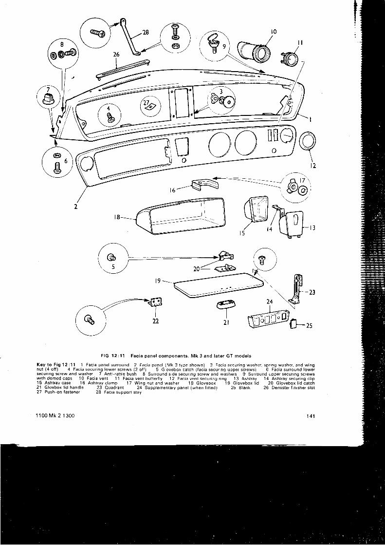
I
@- _ _ = : <
F I G 1 2 : 1 1 F a c i a p a n e l c o m p o n e n t s . M k 3 a n d l a t e r G T m o d e l s
K e y t o F i g l 2 : 1 1 1 F a c i a p a n e l s u r r o u n d 2 F a c i a p a n e l ( M k 3 t y p e s h o w n ) 3 F a c i a s e c u r i n g w a s h e r , s p r i n g w a s h e r , a n d w i n gnut (4 o f f ) 4 Fac ia secur ing lower sc rews (2 o f f ) 5 G lovebox ca tch ( fac ia secur ing upper sc rews) 6 Fac ia sur round lowersecur ing screw and washer 7 Ant i - ra t t le bush 8 Sur round s ide secur ing screw and washers 9 Sur round upper secur ing screwsw i t h d o m e d c a p s 1 0 F a c i a v e n t 1 1 F a c i a v e n t b u t t e r f l y 1 2 F a c t a v e n t s e c u r i n g r i n g 1 3 A s h t r a y 1 4 A s h t r a y s e c u r i n g c l i p15 Asht ray case 16 Asht ray c lamp 17 Wing nu t and washer 18 Glovebox 19 Glovebox l id 20 Glovebox l id ca tch21 Gloxbox l id hand le 23 Ouadrant 24 Supp lementary pane l (when f i t ted) 25 B lank 26 Demis ter f in isher s lo t
@@
\t 2
eI
1 lL I
27 Push-on fastener
1 100 Mk 2 1300
28 Facia support stay
141
6a\ rro\ J \ J O I
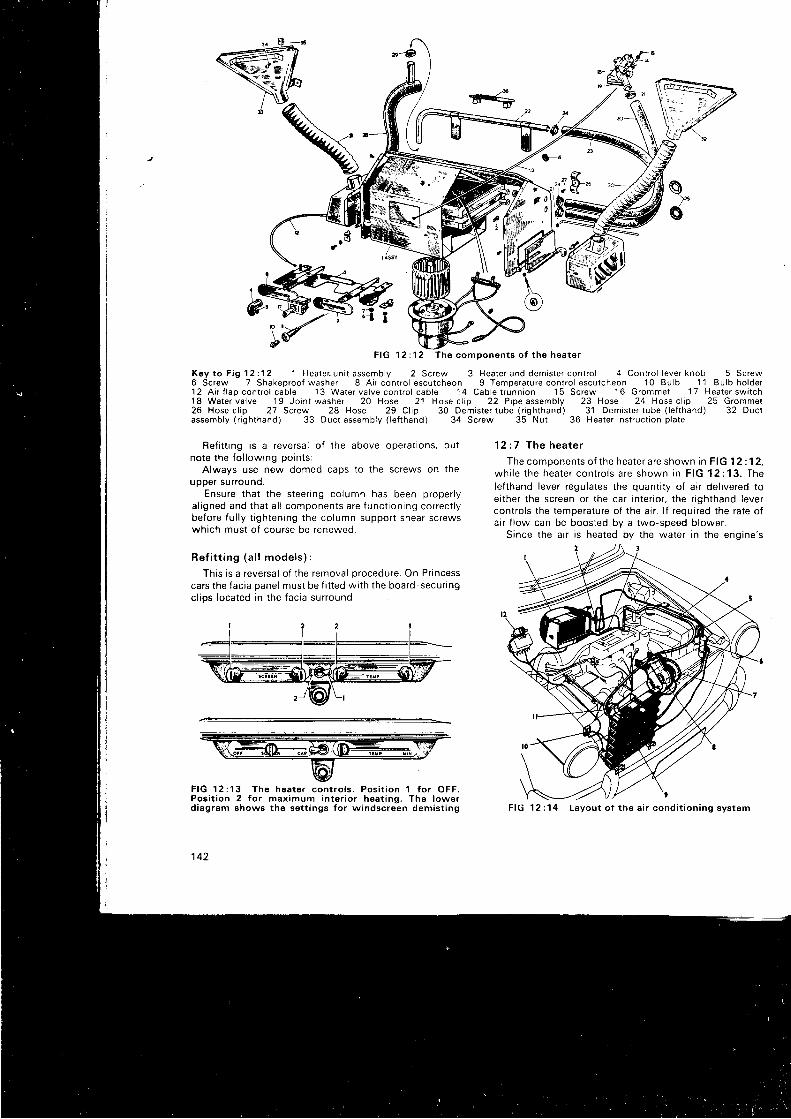
6I
F I G 1 2 : 1 2 T h e c o m p o n e n t s o f t h e h e a t e r
K e y t o F i g l 2 : 1 2 1 H e a l e r - u n i t a s s e m b l y 2 S c r e w 3 H e a t e r a n d d e m i s t e r c o n t r o l 4 C o n t r o l l e v e r k n o b 5 S c r e w6 Screw 7 Shakeproof washer 8 A i r con t ro l escu tcheon 9 Tempera ture cont ro l escu tcheon 10 Bu lb 11 Bu lb ho lder12 A i r I lap cont ro l cab le 13 Water va lve cont ro l cab le 14 Cab le t runn ion 15 Screw 16 Grommet 17 Heater sw i tch18 Water va lve 19 Jo in t washer 20 Hose 21 Hose c l ip 22 P ipe assembly 23 Hose 24 Hose c l ip 25 Grommet26 Hose c l ip 27 Screw 28 Hose 29 C l ip 30 Demis ter tube ( r igh thand) 31 Demis ter tube ( le f thand) 32 Duc lassembly ( r igh thand) 33 Duct assembly ( le f thand) 34 Screw 35 Nut 36 Heater ins t ruc t jon p la te
Ref i t t ing is a reversal of the above operat ions, butnote the fo l lowing points:
Always use new domed caps to the screws on theupper surround.
Ensure that the steer ing column has been proper lya l i gned and t ha t a l l componen ts a re f unc t i on i ng co r rec t l ybefore fu l ly t ightening the column support shear screwswhich must of course be renewed.
Re f i t t i ng ( a l l mode l s ) :
This is a reversal of the removal procedure. On Pr incesscars the facia panel must be f i t ted wi th the board-secur ingcl iDs located in the facia surround.
F IG 12 :13 The hoa te r con t ro l s . Pos i t i on 1 f o r OFF .Pos i t i on 2 f o r max imum i n te r i o r hea t i ng . The l owe rdiagram shows the set t ings for windscreen demist ing
142
1 2 : 7 The hea te r
The components of the heater are shown in FIG 12:12,wh i l e t he hea te r con t ro l s a re shown i n F IG 12 :13 . TheIef thand lever regulates the quant i ty of a i r del ivered toei ther the screen or the car inter ior , the r ighthand levercontro ls the temperature of the ai r . l f required the rate ofa i r f low can be boosted by a two-speed blower.
Since the ai r is heated by the water in the engine's
F IG 12 :14 Layou t o f t he a i r cond i t i on i ng sys t sm
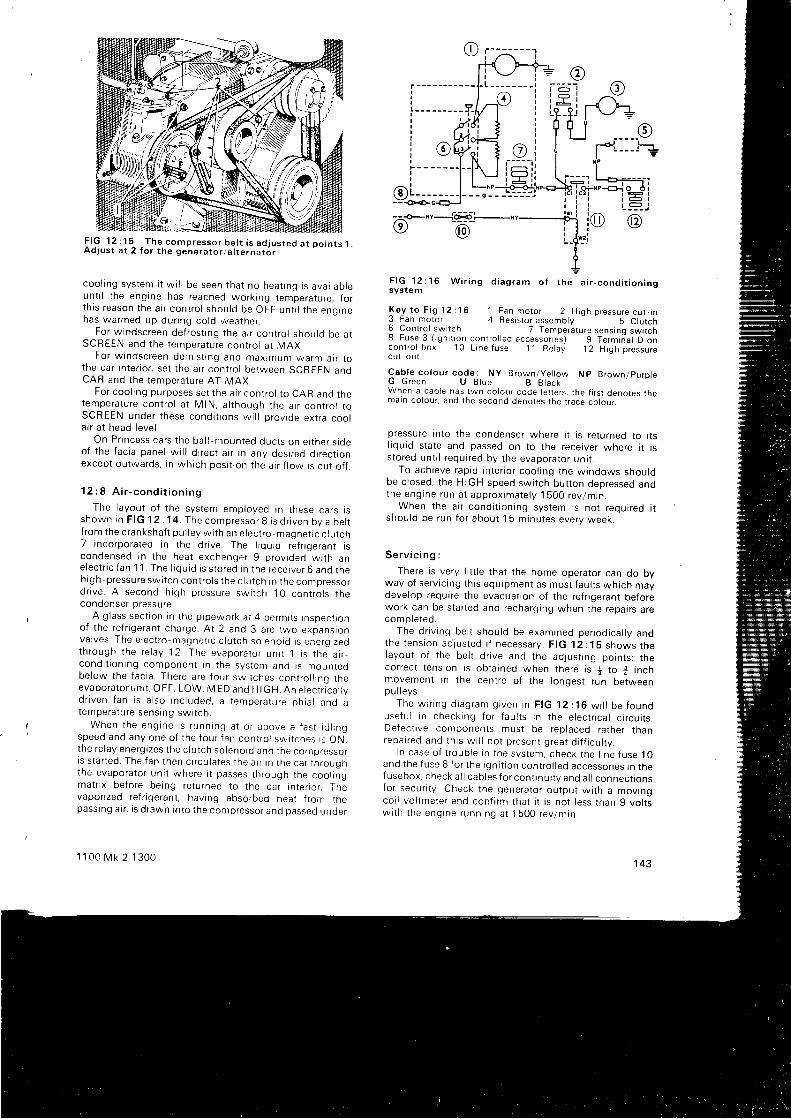
F I G 1 2 : 1 5 ^ - T h e c o m p r e s s o r b e l t i s a d j u s t e d a t p o i n t sA d J u s t a t 2 f o r t h e g e n e r a t o r , a l t e r n a t o r
coo l r ng sys tem i t w i l l be seen t ha t no hea t i nq i s ava i l ab l eun t i l t he eng ine has reached wo rk i ng t empe ra tu re ; f o rt h i s r eason t he a i r con t ro l shou ld be OFF un t i l t he enq rnehas wa rmed up du r i ng co ld wea the r .
Fo r w indsc reen de f ros t i ng t he a r r con t ro l shou ld be a tSCREEN and t he t empe ra tu re con t ro l a t MAX.
Fo r w indsc reen dem is t i ng and max jmum warm a i r t ot he ca r i n t e r i o r , se t t he a i r con t ro l be tween SCREEN anoCAR and the temperature AT MAX.
For cool ing purposes set the ai r contro l to CAR and thetempe ra tu re con t ro l a t M lN , a l t hough t he a i r con t ro l t oSCREEN unde r t hese cond i t i ons w i l l p rov i de ex t r a coo la i r a t head l eve l .
On P r i ncess ca rs t he ba l l -moun ted duc t s on e i t he r s rdeo f t he f ac i a pane l w i l l d i r ec t a i r i n any des i r ed d i r ec t i onexcept outwards, in , ryhich posi t ion the ai r f low is cut of f .
1 2 : 8 A i r - c o n d i t i o n i n g
The l ayou t o f t he sys tem emp loyed i n t hese ca rs r sshown i n F lG12 .14 . The compresso r 8 i s d r i ven by a be l tf r om the c ranksha f t pu l l ey w t t h an e l ec t r o -magne t i c c l u l ch7 incorporated in the dr ive. The l rquid refr igerant iscondensed i n t he hea t exchange r 9 p rov i ded w i t h ane lec t r i c f an 1 1 . The I i qu i d i s s t o red i n t he rece i ve r 6 and t heh igh -p ressu re sw i t ch con t ro l s t he c l u t ch i n t he compresso rd r i ve . A second h i gh p ressu re sw i t ch 10 con t ro l s t necondenser pressure.
A glass sectron in the pipework at 4 permits inspect iono f t he re f r i ge ran t cha rge A t 2 and 3 a re two exoans ionva l ves . The e l ec t r o -magne t r c c l u t ch so leno id i s ene rq r zeoth rough t he re l ay 12 . The evapo ra ro r un t t I t s t he a r r -cond i t i on i ng componen t r n t he sys tem and i s moun tedbe low t he f ac i a . The re a re f ou r sw i t ches con t ro l l i nq t heevapo ra to r un i t , OFF , LOW, M ED and H lG H . An e l ec t r i ca l t ydnven f an i s a l so i nc l uded , a t empe ra tu re ph ia l and atempe ra tu re sens ing sw i t ch .
When t he eng ine i s r unn ing a t o r above a f as t - i d l i ngspeed and any one o f t he f ou r f an con t ro l su r i t ches i s ON.the re l ay ene rg i zes t he c l u t ch so leno id and t he compresso rr s s t a r t ed . The f an t hen c i r cu l a tes t he a t r i n r he ca r t h roughthe evapo ra to r un i t whe re i t passes t h rough t he coo l i ngmatr ix before being returned to the car inter ior . Thevaponzed refr igerant , having absorbed heat f rom thepassing ai r , is drawn into the compressor and passed under
1 1 0 C M k 2 1 3 0 0
F IG 12 : 16 W i r i ng d i ag ram o f t he a i r - cond i t i on i ngsystem
Key t o F i g 1 2 : 1 6 1 Fan mo to r 2 H igh p ressu re cu t - i n3 Fan motor 4 Resistor assembly 5 Clutch6 Control swi tch 7 Temperature sensinq swi tch8 Fuse 3 ( i gn i t i on con t ro l l ed accesso r i es ) 9 Te rm i i a l D oncontrol box '1 0 L ine luse 1 1 Relay 1 2 High pressureCUI -OUT
Cab le co lou r code : NY B rown /ye l l ow Np B rown /pu rp l eG Green U B lue B B lackWhen a cable has two colour code let ters, the f i rs t denotes rnemain colour. and the second denotes the t race colour.
pressure Into the condenser where i t is returned to i tsl iquid state and passed on to the receiver where i t isstored unt i l required by the evaporator uni t .
To ach ieve rap id i n t e r i o r coo l i ng t he w indows shou ldbe c losed, the HIGH speed swi tch but ton deoressed anothe eng ine run a t app rox ima te l y 1500 rev lm in .
When t he a i r - cond i t i on i ng sys tem i s no t r equ i r ed i tshou ld be run f o r abou t 1 5 m inu tes eve rv week .
S e r v i c i n g :
There is very l i t t le that the home operator can do byway o f se r v i c i ng t h i s equ ipmen t as mos t f au l t s wh i ch maydevelop require the evacuat ion of the refr igerant be{orework can be star ted and recharging when the repairs arecomp le ted .
The d r i v i ng be l t shou ld be exam ined pe r i od i ca l l y andthe t ens ion ad jus ted i f necessa ry . F IG 1 2 : 1 S shows rnelayout of the bel t dr ive and the adjust ing points; thecorrect tenston rs obtained when there is + to * inchmovement In the centre of the longest run betweenpu l l evs .
The w r r i ng d i ag ram g i ven i n F tG 12 : 16 w i l l be f ounouse fu l i n check ing f o r f au l t s i n t he e l ec tnca l c i r cu i t s .Defect ive components must be replaced rather thanrepa i r ed and t h i s w i l l no t p resen t g rea t d i f f i cu l t v .
I n case o f t r oub le i n t he sys tem, check t he l i ne f use 10and t he f use 8 f o r t he i gn i t i on con t ro l l ed accessones rn t hefusebox , check a l l cab les f o r con t i nu i t y and a l l connec t i onsfor secur i ty . Check the generator output wi th a movingcoi l vol tmeter and conf i rm that i t is not less than g vol tsw i t h t he eng ine runn ing a t 1 500 rev lm in .
143
A P P E N D I X
TECHNICAL DATA
EngrneClu tc hB rakes
Cooling systemTra nsmiss ion
Elec t r i ca l equrpment
Fuel systemSteering
Capacit ies
lgnit ion systemSuspens ion
Dimens ionsTorque wrench set t ings
W I R I N G D I A G R A M S
F I G 1 3 : ' lF I G 1 3 : 2F I G 1 3 : 3F I G 1 3 : 4F I G 1 3 : 5F I G 1 3 : 6F I G 1 3 : 7F I G 1 3 : 8F I G 1 3 : 9F I G 1 3 : 1 0F I G 1 3 : 1 1F I G 1 3 : 1 2F I G 1 3 : 1 3F I G 1 3 : 1 4
H I N T S O N M A I N T E N A N C E A N D O V E R H A U L
G L O S S A R Y O F T E R M S
I N D E X
Aust in /Mor r is 1 100 Mk 2 and 1300 (1967-71 )Aus t in Amer ica (1968-69)R i ley Kes t re l Mk 2 and 1300 (1967-68)R i l e y 1 3 0 0 M k 2 ( 1 9 6 8 - 6 9 ) , M G 1 3 0 0 M k 2 ( 1 9 6 8 - 7 1 )Wolse ley and MG 1 100 Mk 2 and 1300 (1967-68)Vanden P las Pr incess 1100 Mk 2 and 1300 (1967-71)Wolse ley 1300 Mk 2 (1968-71 )Aus t in Amer ica (1969-71 )Aus t in and Mor r is 1300 GT (1969-71 )Aus t rn and Mor r is 1 100 and 1300 Mk 3 (1971 onwards)Aust in 1300 GT ( l971 onwards)Vanden Plas 1300 ( ' l 971 onwards)Wolse ley 1300 Mk 2 (1971 onwards)Hazard warning system (to be used in conjunction with the appropriatewi r ing d iagram)
1100 Mk 2 1300 145
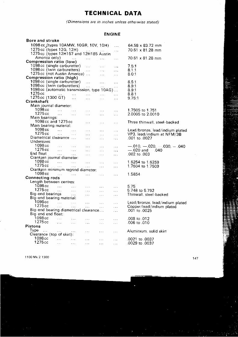
TECHNICAL DATA(Dimensions are in inches unless otherwise stated)
E N G I N E
Bore and s t roket 098 cc , ( tVpes 1OAMW. 10cR, 10V, 10H)1275cc ( types 12c ,12H)1275cc ( types 12H157 and 12H185 Aust rn
America only)Compress ion ra t io ( low)
1 09Bcc (s ing le carbure t te r )1 098 cc ( twin carburetters)1275cc (no t Aus t in Amer ica) . . .
Compress ion ra t io (h igh)1 098cc (single carburerter)1 098cc (twin carburetters)1 098 cc (automatic transmission, type 1 OAG ) . . .1275cc1275cc (1300 GT)
Crankshaf tMa in journa l d iameter :
1 098 cc1275cc
Main bear ings :1O98cc and 1275cc
Main bear ing mater ia l :1 098 cc1275cc
Diamet r ica l c learance . . .
1 098 cc1275cc
Crankp in min imum regr ind d iameter :1 098 cc
Connect ing rodsLength between centres:
1 098 cc1275cc
B i g - e n d b e a r i n g s . . . . . . : . : : . .B ig -end bear ing mater ia l :
1 098 cc1 275 cc
B ig-end bear ing d iamet r ica l c learance.B ig-end end f loa t :
1 098 cc1275cc
Pis tonsTypeClearance ( top o f sk i r t ) :
64 .58 x 83 .72 mm7 0 . 6 1 x 8 1 . 2 8 m m
7 0 . 6 1 x 8 1 . 2 8 m m
7 . 5 . 18 . 1 : 18 . 0 : 1
8 . 5 : 18 . 9 : 18 . 9 : 18 . 8 : 19 . 7 5 : 1
1 . 7 5 0 5 t o 1 . 7 5 12.0005 to 2 .0010
Three thinwal l , steel-backed
Lead/bronze, lead/ indium platedVP3, lead/ ind ium a t NFM/38.001 to .0027
Undersizes:1 098 cc - .01 0, - .020, - .030, - .0401275cc - .020 and - .040
End f loat .002 to .003Crankp in journa l d iameter :
. . 1 .6254 to 1 .6259
. . 1 .7504 to 1 .7509
1 . 5 8 5 4
5.755.748 ro 5 .792Th inwa l l , s tee l - backed
Lead/bronze, lead/ indium platedCopper / lead/ ind ium p la ted.001 to .0025
.008 to .012
.006 to .010
Alumin ium, so l id sk i r t
.0021 to .0037
.0029 to .00371 098 cc1275cc
r 100 Mk 2 1300

Clearance (bottom of skir t)1 098 cc1275cc
Suitable bore size (standard)1 098 cc1275cc
Oversizes avai lablePiston r ingsTop r i ngSecond and third r ingsOi l con t ro l r ing :
1 O9B cc (early)1 098 cc ( later) and 1275cc
Width, top r ing:1 098 cc1275cc
Width, second and third r ings:1 098 cc and 1 275 cc
Width oi l control r ing109Bcc slotted scraper
Fit ted gap, top, second and1 098 cc
th i rd r ing :
1275cc top r ing1275cc second and third r ings
Fit ted gap, oi l control r ing:
.0005 to .0011
.0015 to .0021
64.567 to 64.595 mm (see text)10.622 to 70.655 mm (see text)+ . 0 1 0 a n d + . 0 2 0Three compression, one oi l controlI nternal ly chamfered, chrome-facedTapered
Slotted scraperDuaf lex 61 or Apex
.062 to .0625
.0615 to .0625
. 0 6 1 5 t o . 0 6 2 5
j24 to .125
007 to .0120 1 1 t o . 0 1 6O0B to .013
007 to .012Rai ls .01 2 to .028S i d e s p r i n g s . ' 1 1 0 t o . 1 5 0Rai ls .010 to .040
.002 to .0040015 to .0035.0015 to .035
Fu l ly f loa t ingPressed in connect ing rod
H a n d p u s h
. 8 1 2 3 t o . 8 1 2 5
.0008 to .0015 interference
1 . 6 6 5 5 t o 1 . 6 6 61.62275 to 1 .623251.3725 to 1 .3735.003 to .007Three steel-backed, whitemetal l ined.001 to .002Cha in , f p i tch x 52 p i tches
. 8 1 1 2 5 t o . 8 1 ' 1 7 51.495 to 1 505
1 098 cc,1 098 cc,
slot ted scraoerDuaf lex 61
1 275 cc. ApexRing to groove clearance.
1098cc , top , second and1 098 cc, s lot ted scraper1275cc , top , second and
th i rd
th i rdGudgeon pin type:
1 098 cc1275 cc
Gudgeon p in f i t i n p i s ton :1 09Bcc and 1275cc
Gudgeon p in d iameter :1275cc
Gudgeon p in f i t in connect ing rod1275 cc
Camshaf tJourna l d iameters :'l 098 cc and 1275 cc (front)
1 098cc and 1275cc (centre)1098cc and 1275cc ( rear ) . .
End f loatBearing typeBear ing d iamet r ica l c learanceDr ive
TappetsOuts ide d iameterLength
1 4 8
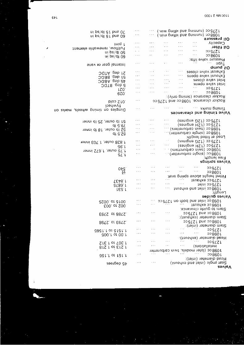
ur bs /q lu r bs /q l
OL09
c l
9 tu ttuU ILU
0001 z l t / \ 00tt
6 u r 1 p r p u e 6 u t u u n t ) c r g L Z L6 u r 1 p r p u e 6 u t u u n t ) c a 8 6 0 !
puep u e
l u l d !l ueu la le a lqeMaua l 'Mo l , l l nJ
u r bs /q t 09u r DS /q l 09
euen l o t ea6 1eu ta1u1
ccrv'6^ap vzJ O 8 8 6 a p l g1 C 8 V 6 a p g t
c c 1 8 6 a p gLZ0',620
ptoc z l0 'laaq^^Al l
s l ieul 's leeqm 6utrut l uo salduutq
rauu l q l 9z ' l a l no q l L9
q l 9 6 rr e u u r q l 8 L ' r a l n o q l z 9
q l I Z 9
rauur to l 'L ' re lno
828 L9 6 1
) e u u l z L q ' t ' r e l n o 9 l L
c t l
Ots'z t6 l
Lt,VB'L9 t89 1
L09 t
9 Z 0 0 . o l I 1 0 0t00 01 200
t,6LZ' OI BBLZ
B6LZ OI E6LZ
s 9 9 L t o l 9 t 9 L !9 6 6 . ; o l 0 0 L
z L t I o l 2 0 0 t. B r Z t o l t L Z !
9 9 L L o l ! 9 L !
searbap gy
a. rnsserd ; tgA l rcede3
r o l l ! , t ! o) J 9 L Z L3c 860 !
:sur l a^ le^ a lnssald' adAgd u n d 1 r g
" saso l s a^ le^ l snPqx l' ' suado a^ le^ l sneqx f
: :i'#:3ll3tj:ixi' c 4 8 6 0 L
: (A1uo 6u r i u t l ) ecue tea ;c l a )30UJJgLZL pue 33860 1
' a3ue . l ea l3 l o ) cou
" s ) l eu l 0u t t u t lsa3ueJee l c pue 6u t t ' ug l e^ len
( s a u t b u a , Z L ) x ) g L Z ,(saut6ua HZI ) s rgLZL
' ' ' (s la] lernqrec urMl) ca 860 !' ( ra l ia rnqrec agbuts ) 33 860 L:qibual Pal lU le Peol
( s a u r b u e , Z r ) n q L Z L( s e u r 6 u e H Z L ) r r 7 L Z L
' (s rauatnq tec u tnn l ) cc860 L' ( ra l la rnq tec a ;6u ts ) 3c 860 L: q l 6ua1 ee t3
sbu r . rds sa^ len
J X 9 L Z Lcc 860 !
leas 6ur tds a^oqe lL l6toq Pa4l ll s n e q x e a J 9 L z L
la lu r 3c 9zz Lp u e l a l u r c a B 6 0 L
:q tbua lsaprnO sen len
p u e l a l u r 3 3 8 6 0 | ,l snPqxa ca 860 L
:a3uerea lc ap tnb o1 ua13r c g L z L p u P c c 8 6 0 L
: ( tsneqxe) ie laurerp ue lsr r g L Z L p u e 3 3 8 6 0 1
: ( lalut) la leu. lelp ulolsJ C 9 L Z Lca 860 L
lalaurerp pesHJJ gLZ L
,"rrn, norrr'nnr'r,"ooJ1:?;l;' !:j ',:o t33 860 !
: ( Io lu l ) re laue lp peaH( tsneqxe pue te lu t ) a ;6ue leag
san len
U O
l sn eqxo
' ' ' c c a l z L u o q l o q
: ( t sneqxa )
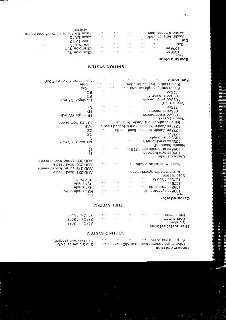
09 1
l s e l l e q L U q o g L o l t Irolsrsar
ql l^^ / v8 secnlz t v l secnlz ! v l secnl9ZO or VZO
A6N uordLUeqJgN uorolueLlc
0 0 2 l n v i o d s ' s r i l c a l a
n so n l 8pau
O Bo 8
u l M l 9 c ' a l 6 u r s
9 H
u!Mt n D 'a l6urs
abpuq uor l s le l i t IUVVzazoI C
u l ^ ^ l e c ' a l 0 u r s N V
T Li t
o lpaou papeo l -6u t tds '080 CnV
alpaau pox l ] '96z cnv
a lpaau papeo; -6u t tds '6Z t CnV
a l p a a u p a x ! j ' L B Z c n v
U I M } Z S Hol6urs yg 11agbuts yg11
ur^ i ro agburs 7911N S
ur lsnvur lsnv
l !oco e 9
J 3 9 L Z L3c 860 l,
:adA1s6n ld 6u r4 redg
LN]ISAS N O t I N 9 l
,r"rr"rnqrn" uqnnl'6uttdstHr:fl t"t '
s ra l l a rnq reo a16u rs ' 6u r rds uo l s !dJ J g L Z I
cr leulo lne 33 860 Lqsauo tqcuAs cc860L
: ( q c u ) a l p a a N3 ) 9 L Z L
. . . 3 l leL lo l le cc 860 L
qsaruorqcu^s 33 860 L: (1eann ) a lpoaN
ec t l a ruV u t l snV ' yuaLu l sn fpe 1a t 1e111uge l p e e u p a p e o l - 6 u r r d s ' e c t t a u u y u l l s n v J J g L Z I
a lpasu pax l ] ' ec l l euJv u l l snv ' JJ9Lz ,
J J 9 L Z I
: . : . . . : c r l e u r o l n e c c S 6 0 L
' qsaurorqcuAs 3c 860 L: (p repue ls ) e lpaaN
. . .: ra lauerp e)oqc
cr leuro lne ecuauv u l l snv
qsauorqcuAs eouau lv u t tsnV:uorlect, t tcadS
. : : ) 3 q L a Lsrleuolne cc 860 | ,
qsauto tqcu ls 3c860L
(r)r"u"r"nd{lc
w3ts^s tSnr
eleur lc loHa leu r l c p loJ
prepuelssbur l las le lsotuJaql
paads lsa l dLund t ty6u rpea r rasA leue se6 l sneqx3
uo rss rLua l sneqx f
ra le l 'Bc l la t !v' " A l ree ' eS l l e tuv
U I
8 l
l o 9 9 L ) o 3 " t Llo06 L ro 3o88lo08 L ro 3oZ8
Nrrs^s 9N1100c
(aur6ue) u rLU/^ar 002 LO C ] u a 3 r c d 9 7 o l 7 u r L u / ^ e r 0 9 8 l e
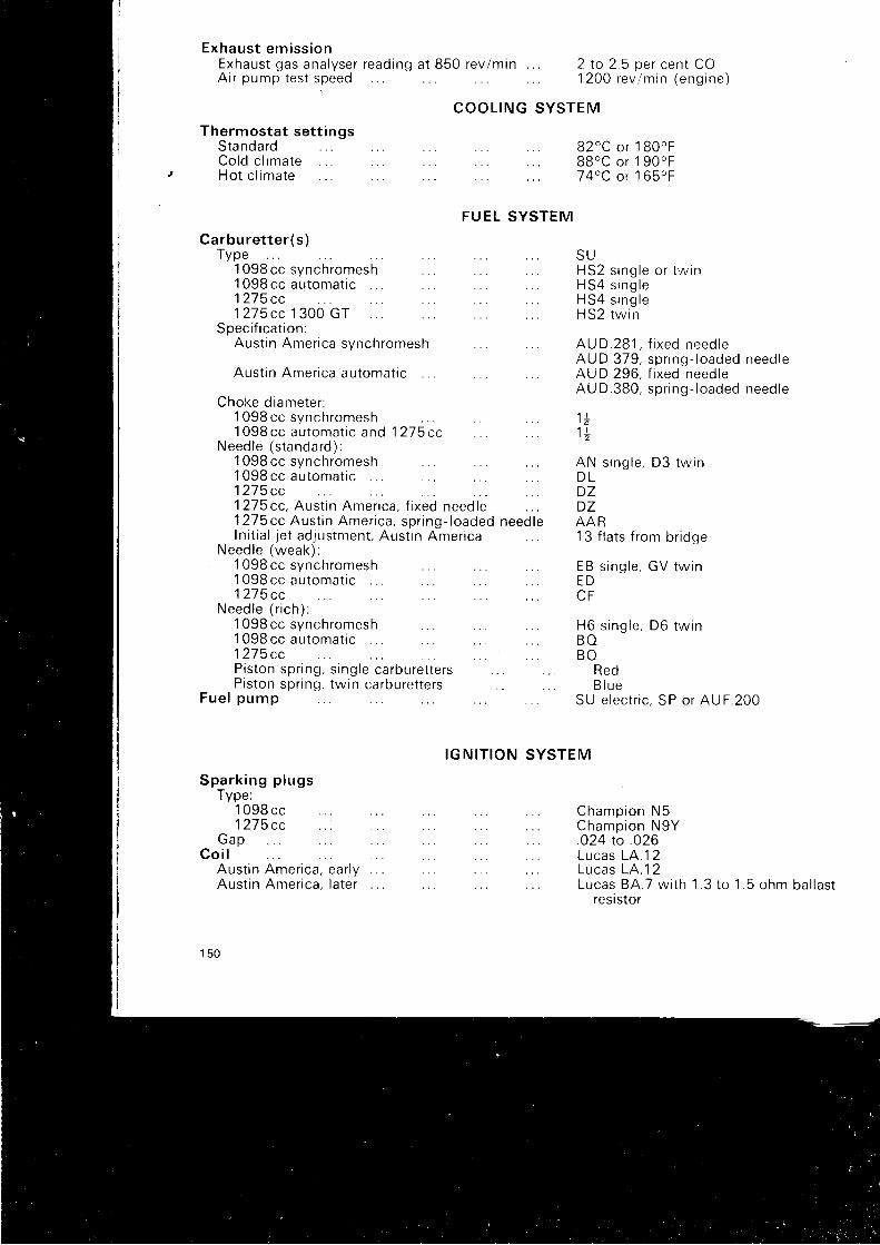
Exhaust emiss ionExhaust gas ana lyser read ingAir pump test speed
Thermostat sett ingsStanda rdCo ld c l ima teHo t c l ima te
Carbure t te r (s )Type'
t Ogg cc synchromesh '
1 098 cc au tomat ic1275cc
S p a r k i n g p l u g sType:'l 098 cc
1 275 cc
a t 850 rev lmin . . . 2 to 2 .5 per cent CO1 2 O O r e v l m i n ( e n g i n e )
B2oC or 1 80 'F88oC or 1 90oFJ4oC or 1 65oF
s i n g l e o r l w i nH 5 4 s i n g l eH 5 4 s i n g l eH S 2 t w i n
A U D . 2 8 1 , f i x e d n e e d l eAU D.379, spr ing- loaded need leAUD 296, f i xed needteAU D.380, spr ing- loaded need le
' l l
1 l' 2
AN s ing le , D3 tw inD LD ZDZAAR13 f la ts f rom br idge
s ing le , GV tw in
H 6 s i n g l e , D 6 t w i nB OB O
RedB l u e
SU e lec t r i c , SP or AUF.20O
C h a m p i o n N 5C h a m p i o n N 9 Y
C O O L I N G S Y S T E M
F U E L S Y S T E M
I G N I T I O N S Y S T E M
S UI-,I JZ
1275cc 1 300 GTSpec i f i ca t i on :
Aus t i n Amer i ca synch romesh
Aus t i n Amer i ca au toma t i c
Choke d iame te r :1 0 9 8 c c s y n c h r o m e s h . . .1098cc au toma t i c and 12 -75cc
Need le ( s tanda rd ) :1 09Bcc svnchromesh1 098 cc automatic1 275 cc1275cc , Aus t in Amei ica , f i xed need le1 275 cc Aus t in Amer ica , spr ing- loadedIn i t ia l je t ad jusrment , Aus t in Amer ica
Need le (weak) :1 098 cc svnchromesh' l 098 cc automat ic1275cc
N e e d l e ( r i c h ) :1 098 cc synchromesh . . .1 098 cc au tomat ic1 2 7 5 c cP is ton spr ing , s ing le carbure t te rsP is ton spr ing , tw in carbure t te rs
F u e l p u m p
E BE D
G a pC o i l
Aus t inAust in
024 to .026
Amer i ca , ea r l yAmer i ca , l a te r
Lucas LA. '12L u c a s L A . 1 2Lucas BA.7 w i th
resistor1 . 3 t o 1 . 5 o h m b a l l a s t
1 5 0
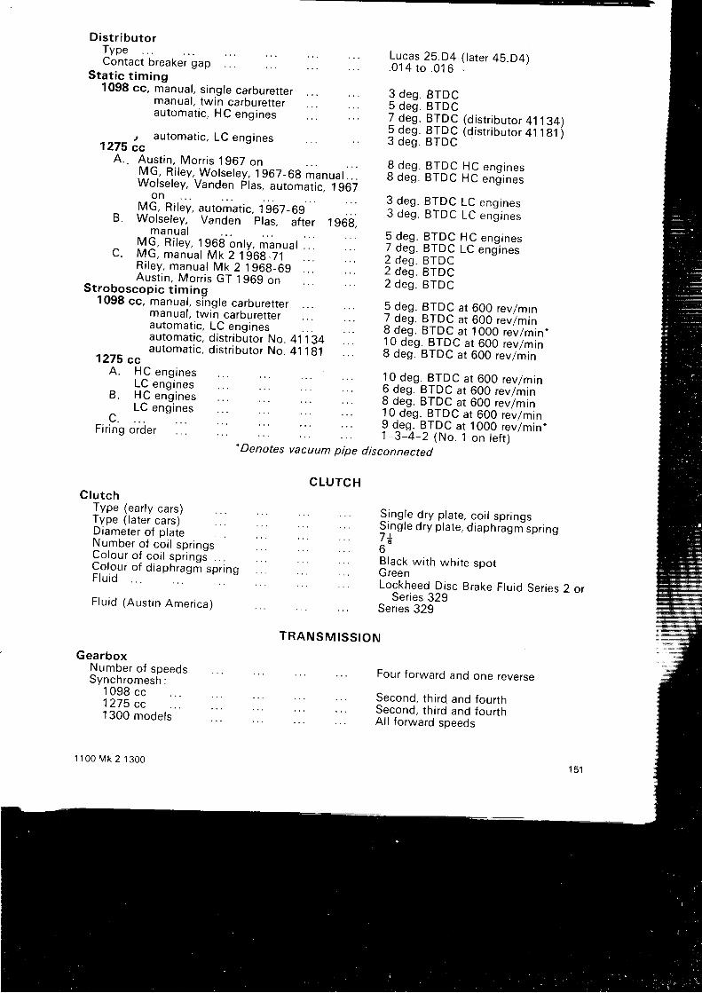
Sta t ic t im ino1098 cc, m'anual, s ingle carburetter
manual, twin carburetterau tomat ic , HC eng ines
, automatic, LC engines1275 cc
A. . Aus t in , Mor r is 1967 onIVI .G, R i tey , Wotse tey , 1967_69 m"nuat . . .Wolseley, Vanden plas, automatic. 1967
on^ .VG, Ri ley, automatic, 19'67_69B. Wolseley, Vanden plas, af ter 1968;
m a n u a l^ M 9 , R i t e y , 1 9 6 8 o n t y , m a n u a t . . . . . .C . MG, manuat Mk 2 19 '69_]1- - . .
R i l e y , m a n u a l M k 2 1 9 6 g _ 6 9 . .Aus t in , Mor r is GT 1969 on
St roboscop ic t im ing1098 cc, manual, s ingle carburetter
manual, twin carburetterau tomat ic , LC eng ines . . .automatic, distr ibutor No. 41 134automat ic , d is t r ibu tor No. 41 1g1
1275 ccA. HC eng ines
LC eng inesB . H C e n g i n e s
c. t_:
""n':.:'Fi r ing order
D is t r ibu torTypeContac t b reaker gap . . .
C lu tchType (early cars)Type ( latei cars) ' . . .Diameter of plateNumber o f co i l spr ingsC o l o u r o f c o i l s p i i n g s . . .Co lour o f d iaphragr i spr ingF lu id
F lu id (Aus t in Amer ica)
GearboxNumber of speedsSynchromesh;
1098 cc1275 cc1300 mode ls
1 1 0 0 M k 2 1 3 0 0
Lu-cas 25.D4 (tater 45.D4). 0 1 4 t o . 0 1 6 .
3 deg. BTDC5 deg. BTDC
Z 9"s PIPQ (distr ibutor 41134)I 9"s 9IPc (distr ibutor 41181i3 des . BTDC
I d"S BTDC HC engrnes8 deg. BTDC HC eng ines
3 deg. BTDC LC engrnes3 deg. BTDC LC engrnes
I4 "s qTDC HC "ns ,n" ,7 deg. BTDC LC ens-ines
2 d e s . B T D C2 deg. BTDC2 deg. BTDC
5 deg. BTDC at 600 revlmin7 deg. BTDC at 600 revlmin8 deg. BTDC a t lOOO rev lmin .1O deg. BTDC a t 600 rev lminB deg. BTDC at 600 revlmin
.. 8 deg. BTDC at 600 revTmin10 deg. BTDC at 600 revlmin9 {"S, B,TDC at 1000 revlmin,1-3-4-2 (No. 1 on te f t )*Denotes vacuum pipe disconnected
C L U T C H
Sing le d ry p la te , co i l spr rngsSing te d ry p ta te , d iaph iagrn 'spr ing7 t6Black w i th wh i te spotG reenLockheed D isc Brake F lu id Ser ies 2 o r
Series 329Series 329
T R A N S M I S S I O N
Four forward and one reverse
Second, third and fourthSecond, third and fourthAl l forward speeds
1 5 1
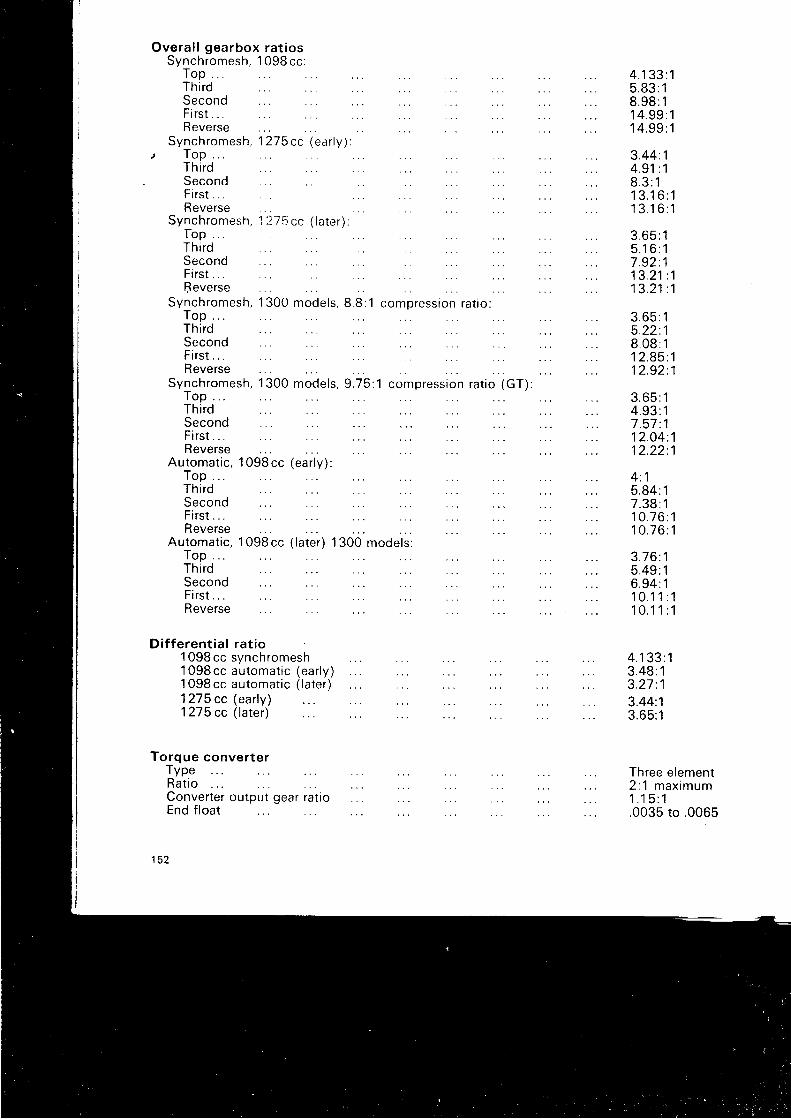
Overa l l gearbox ra t iosSynchromesh, 1098cc :
T o p . . .ThirdSecondFi rs t . .Reverse
Synchromesh, 1 27scc (ear ly ) :TopThirdSecondFi rs t . .Reverse
Synchromesh, 1 275 cc ( la te r ) :rop . .ThirdSecondF i r s t . . . . 1 3 . 2 1 : 1ffeverse
Synchromesh, 1300 mode ls , 8 .8 :1 compress ion ra t io :T o p . .Th i rdSecondF i r s t . . . . 1 2 . 9 5 : 1Reverse . : :
Synchromesh, 1300 mode ls , 9 .75 :1 compress ion ra t io (GT) :T o p . .ThirdSecondFi rs t . . . . 12 .04 :1R e v e r s e . . . : . . . . : : : : : : 1 2 . 2 2 : 1
Automatic, 1 098 cc (early):T o p . .
4.133:15 . 8 3 : 18 . 9 8 : 11 4 . 9 9 : 11 4 . 9 9 : 1
3 . 4 4 . 14 .91 :18 . 3 : 11 3 . 1 6 ; 11 3 . 1 6 : 1
3 . 6 5 : 15 . 1 6 : 17.92:1
3 .65 : 15 . 2 2 : 1B .0B : 1
3 . 6 5 : 14 . 9 3 : 17 .57 :1
ThirdSecondFirst . . ,Reverse
Automat ic , 1098cc ( la te r ) 1300 mode ls :T o p . . . . 3 . 7 6 : 1Th i rd 5 .49 :1Second
4 . 15 . 8 4 : 17.38:11 0 . 7 6 : 110.76 :1
First
(ear ly)( later)
6 . 9 4 : 11 0 . 1 1 : 11 0 . 1 1 : 1
4 .133:13 . 4 8 : 13 . 2 7 : 13.44:13 .65 :1
Reverse
Di f f e ren t ia l1 098 cc1 098 cc1 098 cc1275 cc1275 cc
rat iosynchromeshautomatic (ear ly)automatic ( later)
Torque converterTypeRat io
Three element2 : 1 m a x i m u m1 . 1 5 : 1Converter
End f loatoutpr . l t gear rat to
0035 to .0065
152
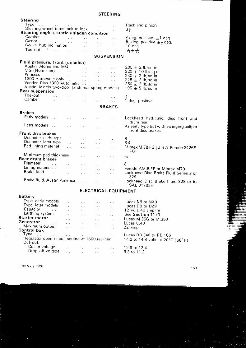
S T E E R I N GSteer ing
Type
Castor
Steer ing wheelS tee r i ng ang les ,
Camber
t u rns l ock t o l ocks ta t i c un laden cond i t i on
Rack and p in ion? r
* deS . pos i t i ve5j deg. posi t ive1 O deg .
1 J 11 6 L 3 2
t 1 d e g .+ + d e q
F lu id p ressure , f ron t (un laden)Aust in , Mor r is and MG
S w i v e l h u b i n c l i n a t i o nToe-out
M G ( N o r m a l a i r )
S U S P E N S I O N
1300 Automat ic on lvVanden P las 1300 Automat icAust in , Mor r is two-door (a rch
Rear suspens ion
Pri ncess
Toe-outCamber
BrakesEarly models
Later models
rea r sp r i ng mode ls )
2 lb /sq in1 0 l b / s q i n2 lb /sq in2 lb /sq in2 lb /sq in5 lb lsq in
posit ive
205 *220 +230 +225 +250 +1 9 5 +I
1 deg
B R A K E S
Fron t d i sc b rakesDiameter , ear ly typeDiameter , la ter typePad l i n i ng ma te r i a l
Min imum pad th icknessRear d rum brakes
DiameterL in ing mater ia l . . .Brake f lu id
Brake f lu id , Aus t in
BatteryType, early modelsType, later nrodelsCapacity
America
Lockheed hydrau l i c , d isc f ron t andorum rear
As ear ly type bu t w i th sw ing ing ca l iperfront disc brakes
I8 .4Mintex M.7B FG (U.S.A. Ferodo 2426F.
F G )+BFerodo AM.B.FE or Mintex M79Lockheed Disc Brake Flu id Ser ies 2 or
329Lockheed Disc Brake Flu id 329 or to
SAE J1703aE L E C T R I C A L
Earthing systemStarter motorGenera tor
M a x i m u m o u t o u tCon t ro l box
TypeRegu la to r open -o rcu i t se t t i ng a t 1 5OO rev lm inC u t - o u t :
Cu t - i n vo l t ageDrop-of f vo l tage
1 1 0 0 M k 2 1 3 0 0
E O U I P M E N T
Lucas N9 or NX9Lucas D9 or DZ912-vo l t , 4O amplhrSee Sect ion 11 : 1Lucas M.35G or M.35JLucas C.402 2 - a m p
L u c a s R 8 . 3 4 0 o r R 8 . 1 0 614.2 to ' l 4.8 vol ts at 2OoC ( 69" F)
1 2 . 6 t o 1 3 . 49 . 3 t o 1 ' 1 . 2

Al te rna torNomina l ou tou tResistance oT rotor winding at 2b'C (68"F)
Windscreen w iper
CAPACITIES
Transmiss ion cas ing , inc lud ing f i l te rAutomat ic t ransmiss ion , inc lud ing i i l te rCoo l ing sys tem, w i thout heaterH e a t e r . . .Fue l tankHydro las t ic suspens ion
D I M E N S I O N S
Overa l l l eng thTrack. s tat ic and u n l a d e n
FrontR e a r . .
Turn ing c i rc le .
T O R O U E W R E N C H S E T T I N G S
E n g i n e a n d t r a n s m i s s i o nCy l inder head s tud nu ts , 109BccCy l inder head s tud nu ts , 1275cc and
U N F b o l t s
n u t s . .
L u c a s 1 1 A C o r 1 6 A C R43 amps3,8 ohms + 5 per cent o r 3 .2 amps a t
1 2 - v o l tLucas 3WA or 14W
(re f i l l 9 p in ts )8| pints1 3 p i n t s5f pints1 p i n t8 g a l l o n s5 pints
12 ft 2l inch
4 f t 3j inch4 ft 2{ inch34 f t 9 inch
M k 340 lb f t50 lb f t (see
text)35 lb f t60 lb f t1 1 0 t o 1 1 5 l b f l25 lb f t6 l b f t2 l b f t5 l b f t6 l b f t1 4 l b f t1 7 t b f t8 t b f t1 0 t o 1 5 l b f t4 l b f tI lb f t1 5 l b f t4 l b f t70 lb f tB l b f t6 l b f t25 lb f t1 8 t b f t6 t b f t1 5 l b f t1 5 0 l b f t1 8 l b f t55 to 60 lb f t70 lb f t1 8 l b f t
B i g - e n d b o l t s . . .Ma in bea r i ng bo l t sFlvwheel centre bol tRocker bracket nutsTransmiss ion case to c rankcaseCy l inder s ide covers (ear ly )Cyl inder s ide covers (deep pressed type)Timing cover f UNF bo l tsT i m i n g c o v e r , fWater pumpWater out le t e lbowOi l f i l t e r ( cen t re bo l t ) . .Oi l f i l ter (car t r idge type)O i l p u m pMan i fo ld t o cv l i nde r headRocker coverCrankshaf t pu l ley nu t . .T ransmiss ion case s tuds , I UNCTransmiss ion case s tuds , 1 f UNCTransmiss ion case s tud nu ts , I UNFTransmiss ion case s tud nu ts , * UNFBottom cover setscrews, ] UNCFi rs t mot ion shaf t nu t . . .Th i rd mot ion shaf t nu tF lywhee l hous ing bo l ts and s tudDriven gear to di f ferent ial cageDr ive shaf t f lange nu tsDif ferent ial housing end cover bolts
154
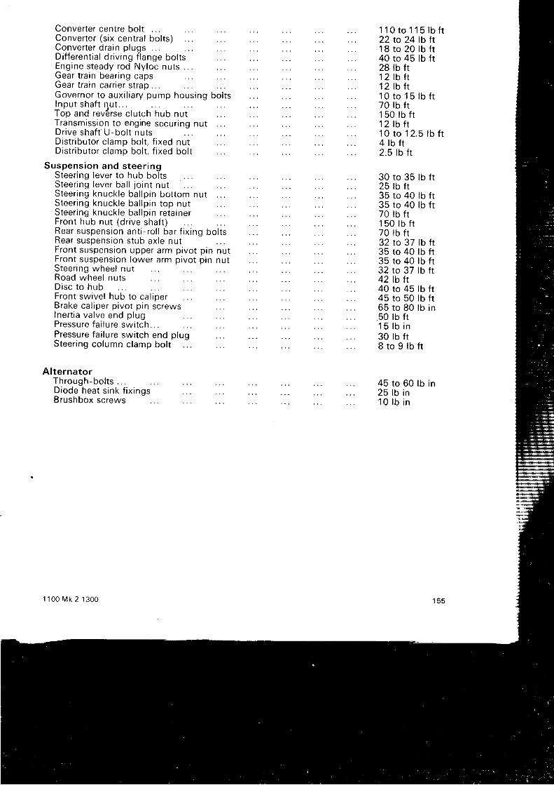
Converter centre bolt .Converter (s ix central bol ts)Conver te r d ra in p lugs . . .Di f ferent ial dr iv ing f lange boltsEngine steady rod Nyloc nuts . .Gear t ra in bear ing capsGear t ra in car r ie r s t rap .Governor to aux i l ia ry pump hous ing bo l tsI n p u t s h a f t n u t . . .Top and rev6rse c lutch hub nutTransmission to engine securing nutDr ive shaf f U-bo l t nu tsDistr ibutor clamp bolt , f ixed nutDistr ibutor clamp bolt , f ixed bolt
Suspens ion and s teer ingSteering lever to hub boltsSteer ing lever ba l l jo in t nu tSteer ing knuck le ba l lp in bor tom nutSteer ing knuck le ba l lp in top nu tSteer ing knuck le ba l lp in re ta inerFront hub nu t (d r ive shaf t )Rear suspens ion an t i - ro l l bar f i x ing bo l tsRear suspens ion s tub ax le nu tFron t suspens ion upper a rm p ivo t p in nu tFront suspension lower arm pivot pin nutSteer ing wheel nutRoad wheel nutsD isc t o hubFront sw ive l hub to ca l iperBrake ca l iper p ivo t p in sc rewsI ne r t i a va l ve end p lugPressure fa i lure swi tchPressure fai lure switch end plugSteer ing co lumn c lamp bo l t . .
Al ternatorT h r o u g h - b o l t s . . .Diode hea t s i nk f i x i nqsBrushbox screws
t 1 0 0 M k 2 1 3 0 0
1B to 20 lb f t40 to 45 lb f t28 lb f t1 2 t b t t1 2 l b f t
1 1 0 t o 1 1 5 l b f t2 2 t o 2 4 l b f t
1 0 t o 1 5 l b f t70 lb f t1 5 0 l b f t1 2 l b f t1 0 t o 1 2 . 5 l b f t
30 to 35 lb f t25 tb f t35 to 40 tb f t35 to 40 lb f t70 lb f t1 5 0 l b f r70 lb f t32 to 37 lb f t35 to 40 lb ft35 to 40 lb f t32 to 37 lb f t42 tb f t40 to 45 lb ft45 ro 50 lb f t65 to B0 lb in50 lb f t1 5 l b i n30 lb ftS t o 9 l b f t
45 to 60 lb in25 lb in1 0 l b i n
4 l b f t2.5 lb f t
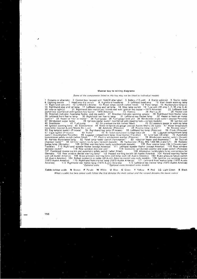
M a s t e r k e y t o w i r i n g d i a g r a m s
Some of the components l isted in this key may not be fitted to individual models
1 D y n a m o o r a l t e r n a t o r 2 C o n t r o l b o x ( e x c e p t w i t h l 6 A C R a l t e r n a t o r ) 3 B a t t e r y ( 1 2 - v o l t ) 4 S t a r t e r s o l e n o i d 5 S l a r t e r m o t o r6 L i g h t i n g s w i t c h 7 H e a d l a m p d i p s w i t c h 8 R i g h t h a n d h e a d l a m p I L e f t h a n d h e a d l a m p 1 0 M a i n - b e a m w a r n i n g l a m p1 ' l R i g h t h a n d s i d e l a m p 1 2 L e f t h a n d s i d e l a m p 1 3 P a n e l l a m p s s w i t c h ( w h e n l i t t e d ) 1 4 P a n e l l a m p s 1 5 N u m b e r p l a t e l a m p ( s )1 6 R i g h t h a n d s t o p a n d t a i l l a m p 1 7 L e f t h a n d s t o p a n d t a i l l a m p 1 8 S t o p l a m p s w i t c h 1 9 F u s e u n i l ( 3 5 a m p 1 - 2 ; 3 5 a m p 3 - 4 )2 0 I n t e r i o r l i g h t ( s ) 2 1 R i g h t h a n d d o o r s w i t c h ( e s ) ( c o m b i n e d w i t h i g n i t i o n k e y b u z z e r - 1 9 7 0 A m e r i c a ) 2 2 L e f t h a n d d o o rs w i t c h ( e s ) ( c o m b i n e d w i t h i g n i t i o n k e y b u z z e r - 1 9 7 0 A m e r i c a ) 2 3 H o r n ( s ) 2 4 H o r n p u s h 2 5 F l a s h e r u n i t26 D i rec t ion ind ica tor , head lamp f lasher , and d ip sw i tch 27 D i rec t ion ind ica tor warn ing lamp(s) 28 R igh thand f ron t f lasher lamp29 Lef thand t ron t f lasher lamp 30 R igh thand rear f lasher lamp 3 ' l Le l thand rear l lasher lamp 32 Heater o r f resh-a i r motorswi tch" 33 Heater o r f resh a i r motor - . 34 Fue l gauge 35 Fue l gauge tank un i t 36 Windscreen w iper sw i tch (except Pr incess)37 Windscreen w iper motor 38 lgn i t ion /s ta r le r sw i tch (combined w i th s teer ing lock-cer ta in mode ls ) 39 lgn i t ion co i l40 Distr ibutor 41 Fue l pump 42 Oi l p ressure swr tch (when f i t ted) 43 Oi l p ressure gauge or warn ing lamp44 lgn i t ion warn ing lamp 45 Speedometer 46 Water tempera ture gauge (except Aus t in /Mor r is De-Luxe) 47 Waler tempera turet ransmi t te r (excep l Aus t in /Mor r is De-Luxe) 48 Ammeter (Pr incess) 49 Reverse lamp swi tch . . 50 Reverse lamp ' *63 Fog lamp(s) sw i tch (Pr incess) 54 R igh thand fog lamp (Pr incess) 55 Le f thand fog lamp (Pr incess) 56 C lock (Pr incess)5 7 C i g a r l i g h t e r ( P r i n c e s s ) 6 0 R a d i o - 6 4 B i - m e t a l i n s t r u m e n l v o l l a g e s t a b i l i z e r 6 5 L u g g a g e c o m p a r t i n e n t l a m pswi tch (Count ryman/Trave l le r ) 66 Luggage compar lment Iamp (Count ryman/Trave l le r ) 67 L ine luse (35 amp) 75 Automal ict ransmiss ion sa fe ty sw i tch (when f i t ted) 77 E lec t r i c w indscreen washer (Pr incess) 78 Windscreen washer 3wi tch (Expor t )81 Asht rav i l l umina t ion lamo 82 Pane l lamD-heater sw i tch i l l umina t ion" 83 lnduc t ion heater and thermosta t * ' 84 Suc t ionchamber heater ' * 94 Oi l f i l te r swr tch (ear ly synchromesh mode ls ) 95 Tachometer (R i ley , MG 1300 Mk 2 and GT) 99 Rad iarorb a d g e l a m p ( W o l s e l e y ) 1 0 5 O i l f i l t e r w a r n i n g l a m p ( e a r l y s y n c h r o m e s h m o d e l s ) 1 0 5 R e a r i n t e r i o r l a m p ( M k 3 C o u n t r y m a n /T r a v e l l e r ) 1 1 0 R i g h t h a n d r e p e a t e r f l a s h e r ( e x c e p t A m e r i c a ) 1 1 1 L e f t h a n d r e p e a t e r f l a s h e r ( e x c e p t A m e r i c a ) 1 1 5 R e a r w i n d d wdemis le r sw i ich- 1 1 6 R e a r w i n d o w d e m i s t e r u n i t ' 118 Combined w indscreen washer and w iDer sw i tch (Pr incess)131 Combined reverse swi tch and au tomat ic sa fe ty sw i tch (when f i t ted) 139 A l te rna t ive numberp la te lamp connect ions fo rGermany 150 Rear w indow demis t warn ing lamp ' 153 Hazard warn ing swi tch (a l l Aus t in Amer ica) 154 Hazard warn ing f lasherun i t (a l l Aus t in Amer ica) 159 Brake pressure warn ing lamp and lamp push (a l l Aus l in Amer ica) 160 Brake pressure fa i lu re swi tch(a l l Aus t in Amer ica) 164 Ba l las t res is tance or cab le (a l l Aus t in Amer ica except very ear ly mode ls ) 168 lgn i t ion key warn ing buzzer( 1 9 7 0 A u s t i n A m e r i c a ) 1 7 0 R i g h l h a n d l r o n t m a r k e r l a m p ( 1 9 7 0 A u s t i n A m e r i c a ) 1 7 1 L e f t h a n d f r o n t m a r k e r l a m p ( 1 9 7 0 A u s t i nA m e r i c a ) 1 7 2 R i g h t h a n d r e a r m a r k e r l a m p ( 1 9 7 0 A u s t i n A m e r i c a ) 1 7 3 L e f t h a n d r e a r m a r k e r l a m p ( 1 9 7 0 A u s t i n A m e r i c a )
. Optional extta .. Optional extra/standard some models
C a b l e c o l o u r c o d e N B r o w n P P u r p l e W W h i t e U B I u e G G r e e n Y Y e l l o w R R e d L G L i g h t c r e e n B B l a c k
When a cable has two colour code letters the fitst denotes the main colour and the second denotes the ttacer coloul
1 5 6
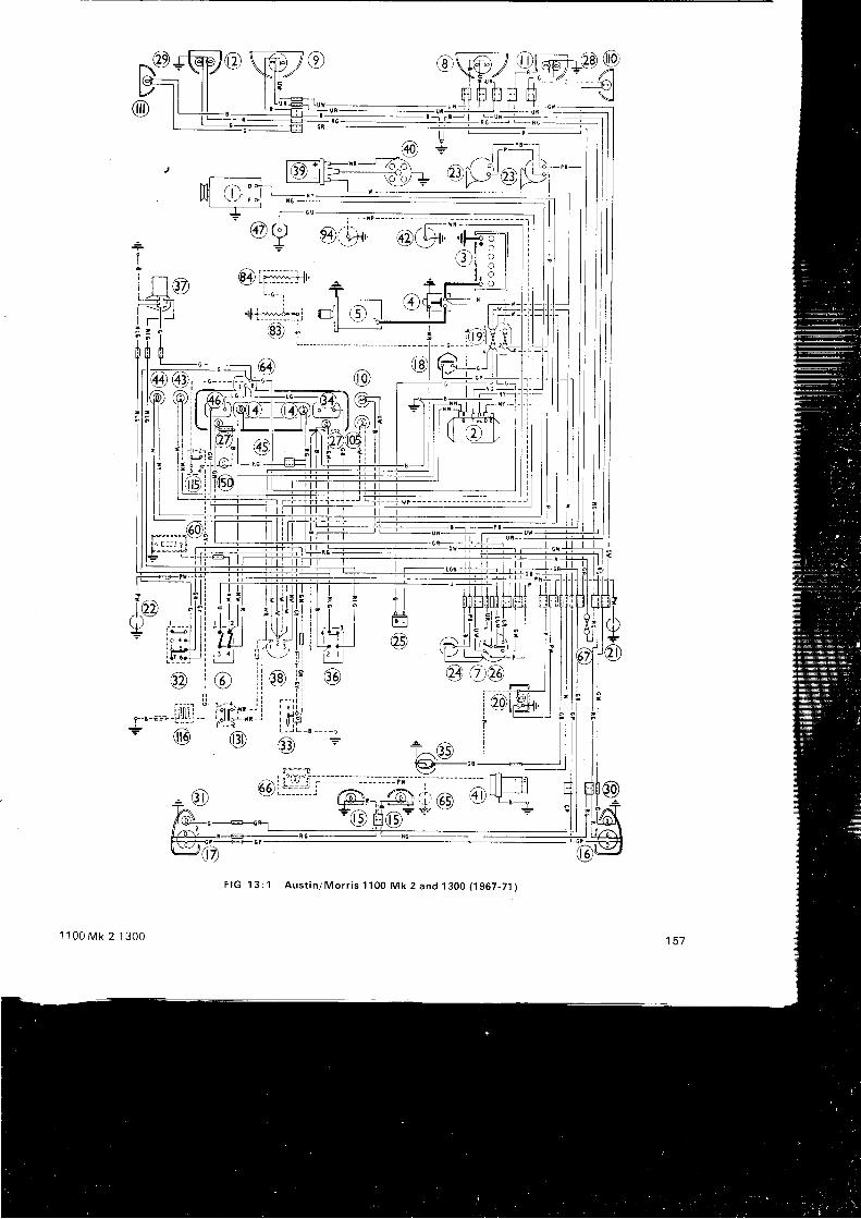
l l -
- |^ t I
/< \J d t l -€tl!-r0
, i li l lul#tiI,irll'.t,i u | ?
ol/@t - t ll l ti r it i llJi-L t t t v
ffi
= - zl t
- l - r I
i ' 1 t I-ii l
@
lo7)r : ) -\+/ f
r-l -€-:]
F I G 1 3 : 1 A u s t i n / M o r r i s 1 1 0 0 M k 2 a n d 1 3 0 0 ( 1 9 6 7 - 7 1 )
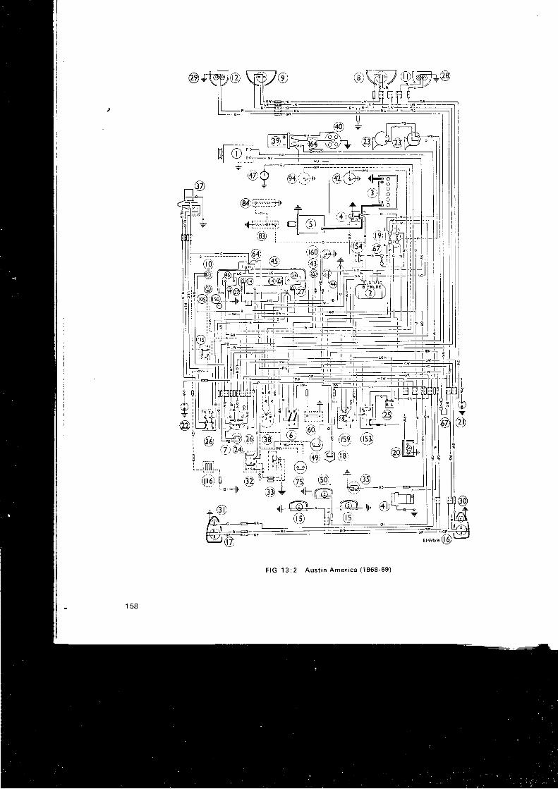
Y ,-pg...-€ | T'-----tl
/^ l. I zl-l:
@F-;L'8FFa
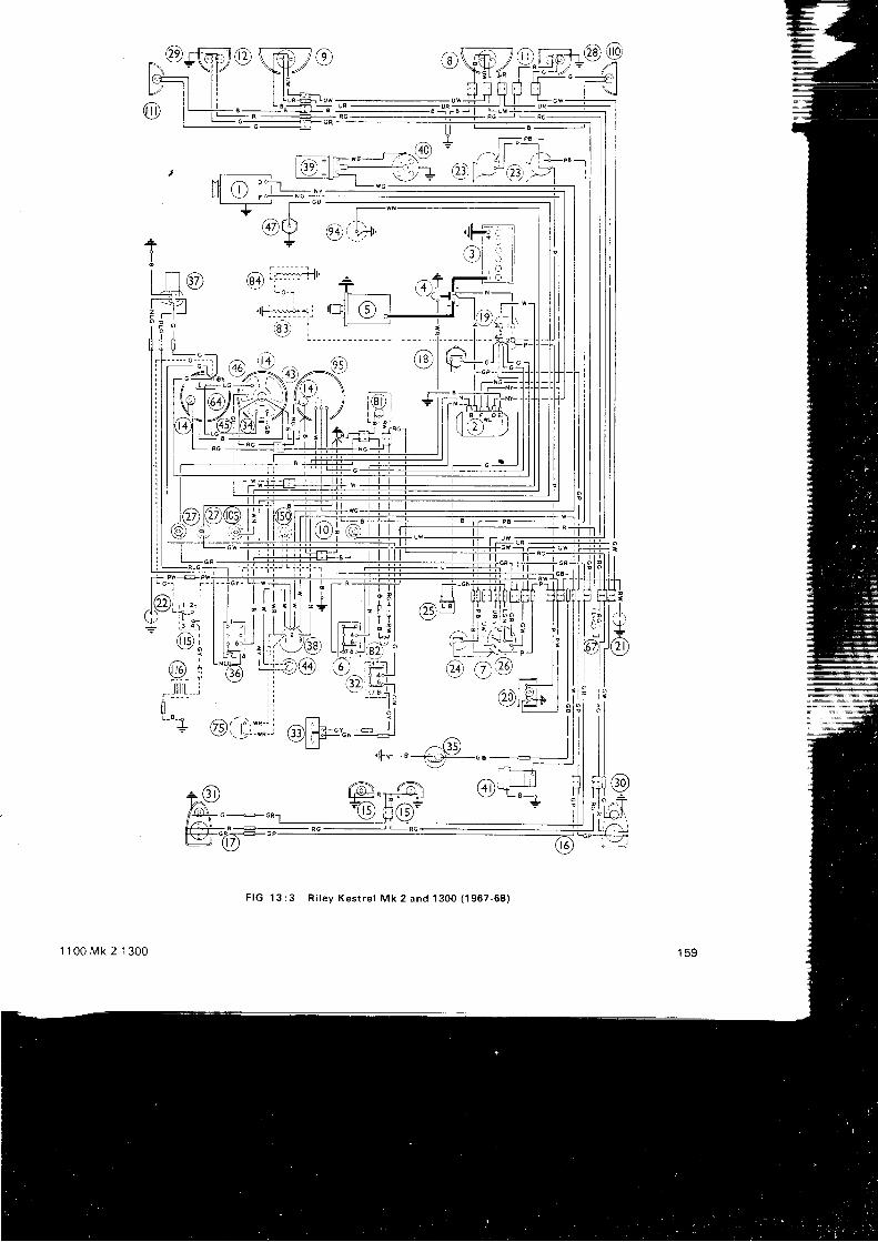
a;\T,_fh-tBJ---1ji 3 9 1 r y ' ;r " - , - \ :
M l - l
l l H / , \ -
' I
--__r-
F IG 13 : 3 R i l ey Kes t re l Mk 2 and 1300 (1957 -68 )
1 100 Mk 2 1300
@J-^-Q'
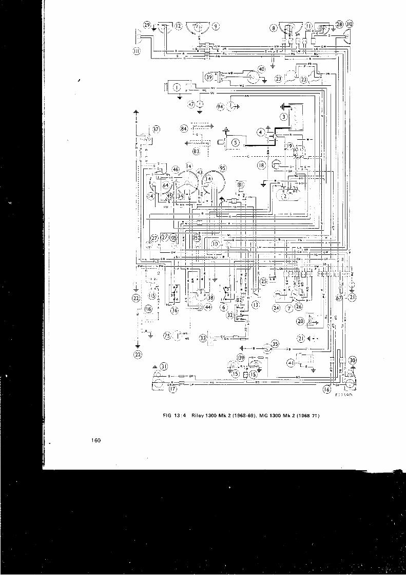
d l l _ _ ;
. 4 n ) r I f ' -t ---|Fws ;-:Z*\ : -l
I(:r) >------- + ]}f 'rJ;1'-v -u----l
\-. ? : /- <9
t - r I
=l
SZi l- t -
I
1_
I r 5 -
F I G 1 3 : 4 R i l e y 1 3 0 0 M k 2 ( 1 9 6 8 - 6 9 ) , M G 1 3 0 0 M k 2 ( 1 9 6 8 - 7 1 )
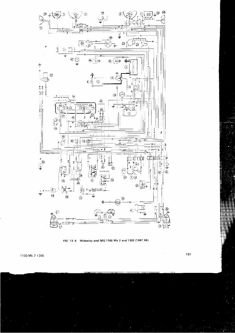
F I G 1 3 : 5 W o l s e l e y a n d M G 1 1 0 0 M k 2 a n d 1 3 0 0 ( 1 9 6 7 - 6 8 )
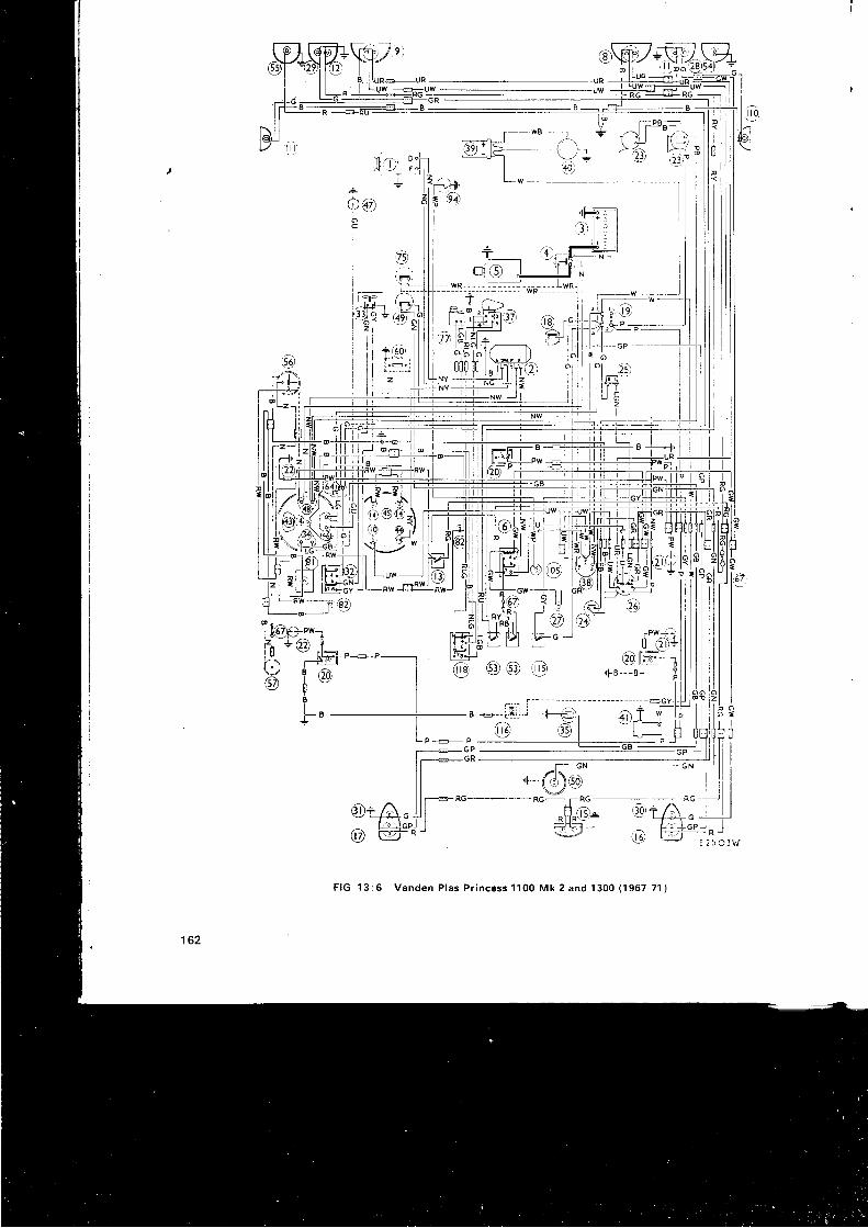
+ac
IIiI
I
ulT_' , ,
]+-- + -F-"-G.o J___ff=] i---,:Il-ll,,r'-----:f.!Ll I - w
,fi;!?
' f l -cPo
lr .8iI rd-rl -
ilfit_l 5
I t :
0iCI{ l tI /ff
I
r r l .l u /
I :-',
GWT r. o t l) f \J
| '<t
] U
@ - @ @ o
F IG 13 :6 Vanden P las P r i ncess 1100 Mk 2 and 1300 (1967 -71 )
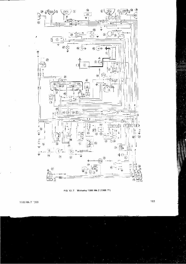
!yo
- P 9 -^ l - r - l \
D ( ! - j - ; i L 5 - "
F IG 13 : 7 Wo l se lev 1300 Mk 2 ( 1968 -71 )
1 1 0 0 r v k 2 1 3 0 0

NLI Ll_ J_:v_
-- 'n od)r - - +
.-2E1- | s-a l;;;;;l1- l= ,Zr l | ' . :
EF",dli ' 6--a T--B -'f, I 1F:^;;+r dl G
, 6 r u t -
lnnF o ;f-9UUAl l l rr l r
1 , = * - ^ - (
l : , " - J - " - l 1 9 (l l i i - - ] ' r " r lI jF-O (f i - rr ,*-- .=f f i (i r,ll -
ll ti_9(qc, 1 oplil:-fi Ii E t \ i \ E 5 f " J - : l l d a r l ib q ' L l l s o ) l , : ' | \ ' v r l
t l l , l K i - J , ' ! 1 ; -nc r r + /1. ? r i r l , "
" r - - - r r, i i t , ' _ . i -c^r- - - -_ i - i - -_+! ! - L jl l l r l j , r : ' l ! I I r l Jl l l " $ " , : ' l - i l r € - !
, t [ wt i i l 5 ) i | | . - - - - - - - - - - - - -
l ' l ; " - B -, r u t , , ^ . - - - - -
l - I -en'-.::-i : i r i , ; ' - l t l - - -1 .
i,.-,"--l- ,
-r-1^--:
F IG 13 : 8 Aus t i n Amer i ca (1969 -71 )
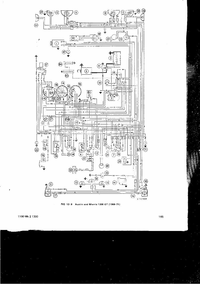
^rqnr\m7o oS/p,@==@tlcEr ll I l i rl; i F;+ H- .---41l > l l l l I r l : r J ! - # , , i , + | \-
l l i l l L u n - t - L u w - u w + - - l l l l l L - G w -- - ^ - 'r g r J- - - . . - - - , . - - r "
r
Ml ,^ oo :1l l ! i l ) | [ - -NYW i V r + t c -
t--f-=i f--GU
v l, ^ / N
(47) |. d.,- Y
-T ? e i i s l
o - - - - - - - - | ^ l
i - ^ n l - - = . j J r A ^ : # _ i _[La, ae'L;, t_ @&tr=r-=ZFi r l. i?
-Zr r\f)2. \
#))-P. ) 16r st':qi
J---t | il l
F IG 13 : 9 Aus t i n and Mor r i s 1300 GT (1969 -71 )
' I 100 Mk 2 1300
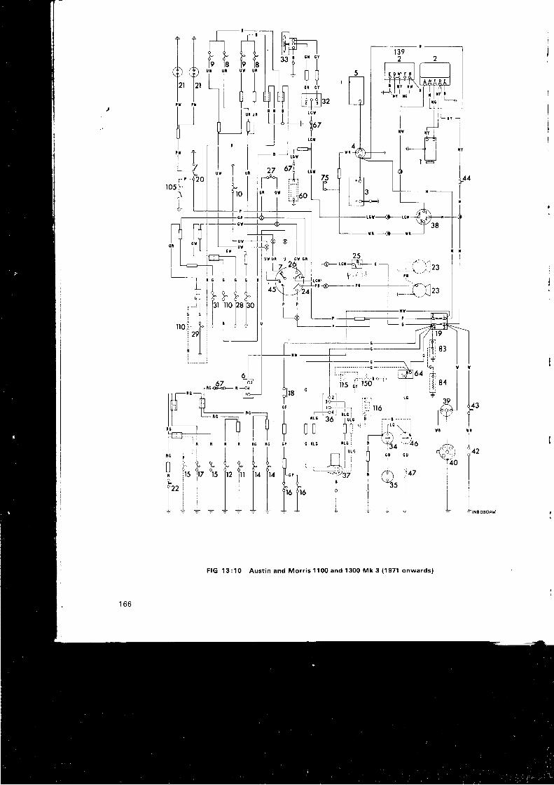
T it i
A AY ' Yl2t l2lt t
JosTi
II1ln
iT
ilL.,Ir
frU
L122IL
F IG 13 :10 Aus t i n and Mor r i s 1100 and 1300 Mk 3 ( 1971 onwards )
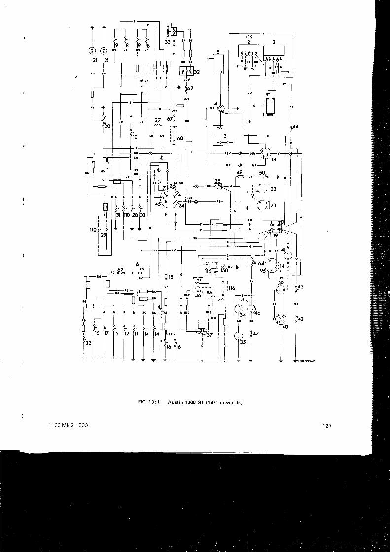
-lI
L.I5
T Tl l
A AY ' Yl'' 12't l
l_lII
i Tl o /
e20
d-\Z
.-.|23
ili tl;,r
l:.,_I-+
X'YoT117
. T, l1
Lrrol- jVI
F I G 1 3 : 1 1 A u s t i n 1 3 0 0 G T ( 1 9 7 1 o n w a r d s )
1 1 0 0 M k 2 1 3 0 0
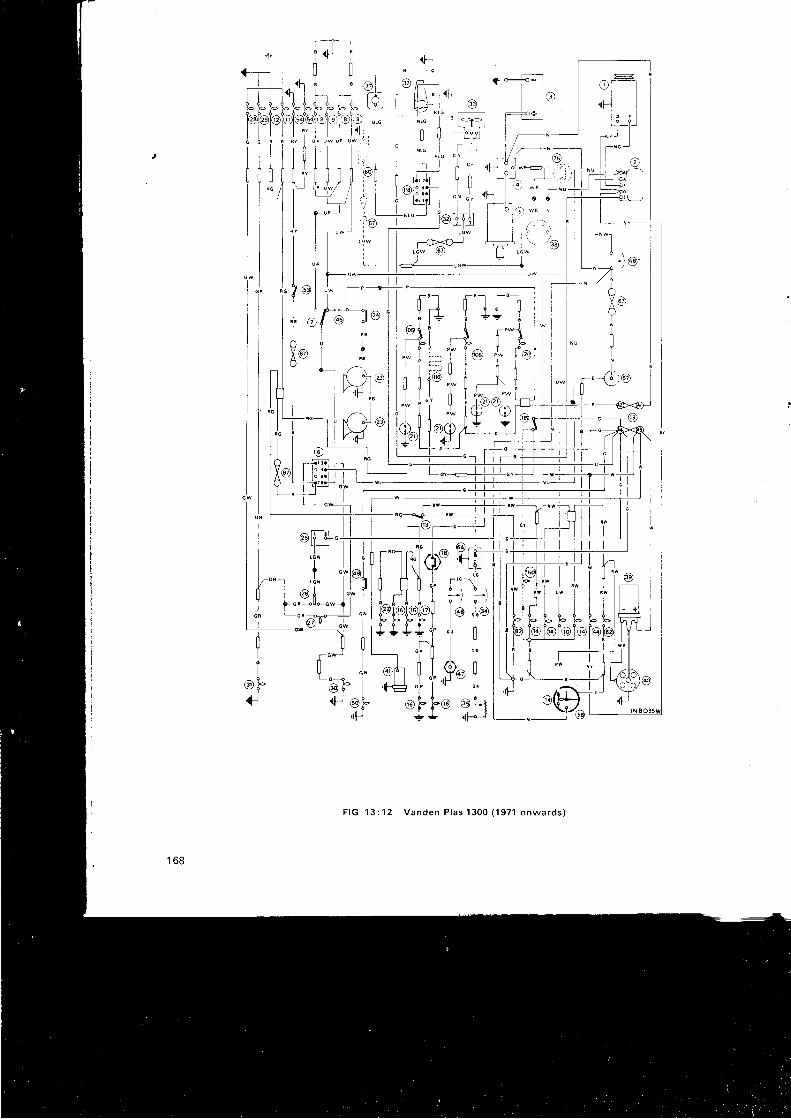
F IG 1 3 : 1 2 Vanden P las 1 300 (1 971 onwards )
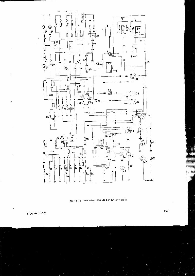
TA9',
l lI
tHilr:ll l 'AY
l J r 4
4o^#*6r-fiI I L - ]l l l| -ur---u I
25
;e-".-s-.
ttofTI
t f t t ifui
Ir
II1ln
iT
if.'L
TtoI
AU
t122It
l l tl A l 4 7l Y ' lt l l! r +
F IG 13 :13 Wo lse lev 1300 Mk 2 ( 1971 onwards )
1 1 0 0 M k 2 1 3 0 0
1 9 \ l
? td r iY I
? ll l: p l
r@l l
d,-f.IL= n 8
I
I
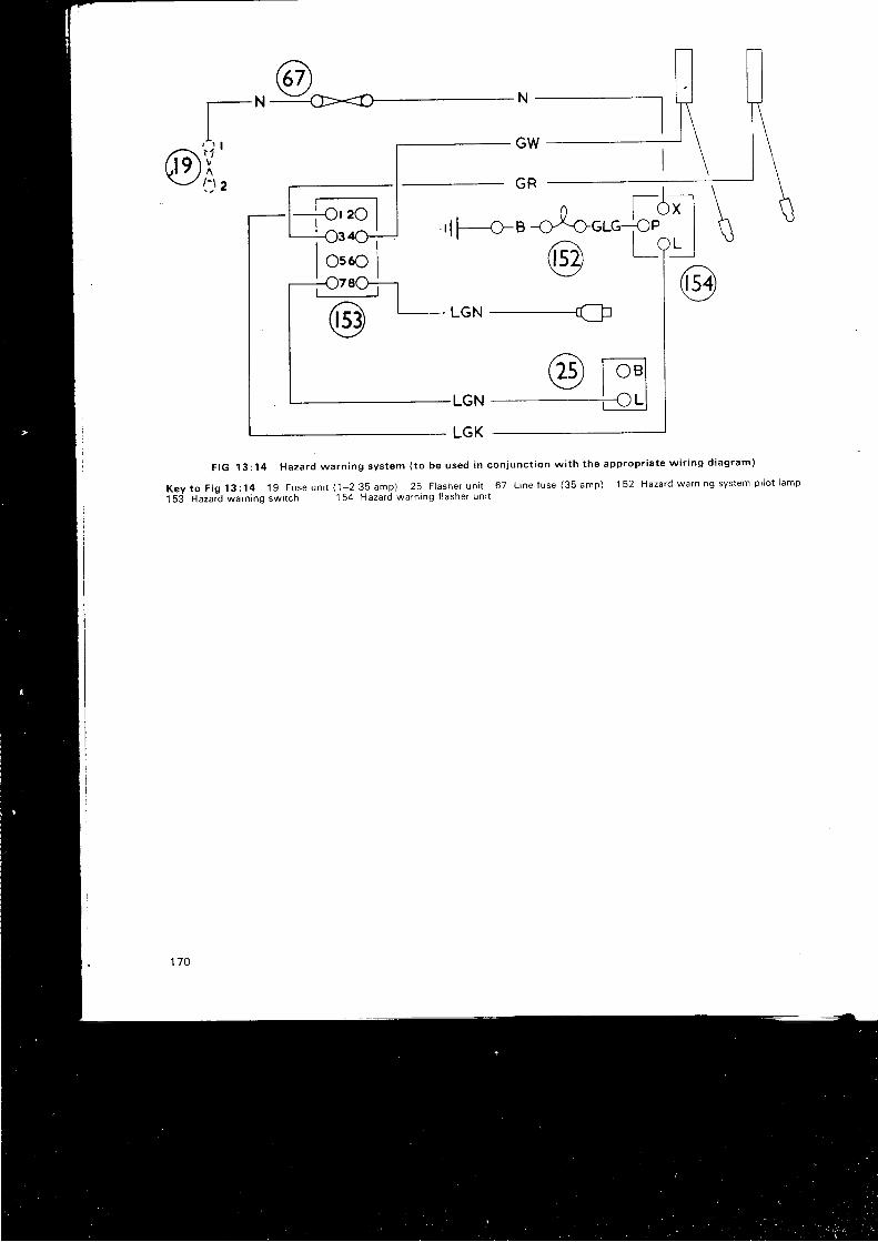
GR
rlreBoto"r"5
aO ,--f< - lr) ucN -------{:
LGN
LGK
F I G 1 3 : 1 4 H a z a r d w a r n i n g s y s t e m ( t o b e u s e d i n c o n i u n c t i o n w i t h t h e a p p r o p r i a t e w i r i n g d i a g r a m )
K e y t o F i g 1 3 : 1 4 1 g F u s e u n i r ( 1 2 3 5 a m p ) 2 5 F l a s h e r u n i r 6 7 L i n e f u s e ( 3 5 a m p ) 1 5 2 H a z a r d w a r n i n g s y s t e m p i l o t l a m p
t5 i Hazat? warn ing swi tch 154 Hazard warn ing f lasher un i t
( 2 5 ) l o e l\--l I I, / - \ t I
I v - l
170
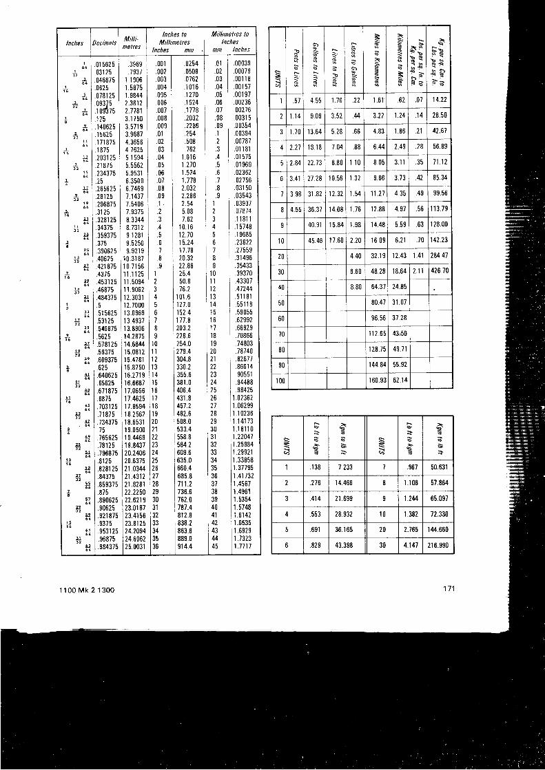
Inches DecinalsMilli-neltes
lnches toMillinetres
lnches nn
Milhnetrcs tolnches
nn lnches
I
i
+
_3a
12
i 6
a
13 2
3
_l3 2
-L
ea3 2
I
l_3
-L3 2
u
1:1
_a3 2
ll
ell3 2
2.3
25
!!3 2
2t
1!
ll3 2
!-1
9l
L 73 2
q!
]J
3!
lJ
ta
!5
3 24f
42
25
t_1
u2f3 2
5_Z
ua 2
5!
4_1
31
!3
I
I
I
!!
!a
.01 5625
.031 25
.046875
.0625
.078'125n q ? 7 6
iogtis1 2 5.140625.1 5625.1 71 875.1 875.2031 25.21 875.2343i5.25.265625.28125.296875.31 25.328r 25.34375.359375.375.390625.40625.421875.4375.4531 25.46875.484375(.51 5625.531 2 5.546875.5625.5781 25.59375.609375.625.64062 5.65625.671 875.6875.7031 25.71 875
I .734375l i 5| .765625I r o r r r
| .796875I 0 1 1 E
| .8281 25| .o+irs1 .85s375I e ? q
| .8906251 . 9 0 6 2 5| .szr azs1 . 9 3 7 5I o ( 1 1 t q
| . 9 6 8 7 5I .984375
.3969
.7937I .1 9061 58751.98442.381 22.77813.1 7 503.571 g3.96874.36564 16255 15945.55625. 35316.350 06.74691.14317.54067.93758.33448.13129.1 2819.5250o q ? l q
10.31 87'10 .7156'11 . ' l 1251 1 .50941 1 .90621 2 .30311 2.70001 3 .09691 3.493i1 3.89001 4.28751 4.6844I 5.081 21 5.4781I 5.87501 6 . 2 7 1 91 6.66871 7.065617.46251 7.85941 8.25621 8.65311 9.05001 9.44691 9.843720.240620.63752'r.034421 .43122t .828122.225022.621 923.0r 8723.41 5623.81 2524.209424.60622 5.003r
.001
.002
.003
.004
.005
.006
.00i
.008
.009
.01
.02
.03
.04
.05
.06
.07
.08
.09
. 1
.2
.+
. 67.8. 9,l
2J
5o78I
t 0l 11 21 31 4l 5l 61 1t 8l 9202122232418,
26272829303'r3233343536
.0254 I 01
.0508 I .02
.0762 I .03
.1016 | . 04]270 .05.1524 I .061778 j 07.2032 .082286 L .09.254 i . r.508 .Z162 I .3
1 .016 I .o1.270 .51.524 I .61.118 j .72.032 .82.286 r .92.54 I 15.08 27.62 I 3
10 .16 i 412.10 515.24 I 617.78 | 720.32 I22.86 I25 .4 i 1050 .8 I 1116.2 12
101 .6 I 13121 .0 I 14152 .4 15177 .8 ',16
203.2 i 1 7228.8 ',18
254.0 1 I27s .4 120304.8 I 21330.2 22355.6 23381.0 24406.4 I 25431.8 L 26457 .2 | 21482.6 j 28508.0 29533.4 30558.8 | rr584.2 I 32609.6 3363s.0 I 34660.4 | 35685.8 I 36711 .2 137736.6 I 38762.0 | 3e787.4 i 40812.8 I 41838.2 | 42863.6 | 43889.0 | 449'14.4 145
.00039
.00079
.00' l 18
.001 57
.001 97
.002 36
.00276
.0031 5
.00354
.00394
.00787,01 181.01 575.01 969.02362,02756.031 50
I .03543I . 0 3 s 3 7
.07874
. 1 1 8 1 1I .1 57481 . 1 e 6 8 5
.23622I .27559| . r r + s o
.35433
.39370
.43307
.41244,5'1 1 81. 5 5 r 1 8.59055.62992.66929.i0866,74803.78740.82671.866 1 4.90551.94488
I s8425I 1.023621.06299
1 1 .1 0236I 1.1 41 731 . 1 8 ' 1 1 0
11.22047| 1 .25s84I 1 .299211.33858
I 1 .377e5| 1 .41 732I 1 .45671 .4961
I 1 .5354I r .sr+o| 1 .6142I 1 .6535| 1 .6s2e| 1.7323| 1.1111
=?j
\:
d
sa
=S:
s=6J
\
s6-.
a^
G
a-i
T
=d-
$
6 :t qq Ss ss l
,+5 q
* s- s
I 57 4.55 1 .76 .22 t .6 ' l . h t .07 14.22
2 l . '14 9 .09 3.52 u 3.22 1.24 . t s 28.50
I .70 l3 .64 5.28 . o o 4.83 I .86 21 42.67
2.71 1 8 . 1 8 /.04 .88 6.44 2.49 28 56.89
2.84 22.73 8.80 L l 0 8.05 3 . 1 1 35 71.12
6 3.41 21 .28 10.561.32 9,66 3.73 85.34
7 3.983'r .82 12.321.54 11.21 4 . J i .49 99.56
8 4.55 36.3714.081 . 7 6 12.88 4.97 .56 ' l '13.79
q 40.91I 5.84 1 . 9 8 14.48 5.59 . o J | 28.00
l 0 45.4617.602.20 16.09 6.21 .70 142.23
20 4.40 32.191 2.43 t .41 284.41
30 6.60 48.2818.642.11 426.70
40 8.80 64.3724.85
50 80.473 1 . 0 7
60 96.5637.28
70 1 12.65 43,50
80 1 28.7549.71
90 r44.8455.92
100 r 60.9362.14
=:.t s
xS
s E9j
+
s
,sss+
I 138 7.233 .967 50.631
276 14.466 8 t.r 06 57.864
? .414 21 .699 1.2M 65.097
.553 28.932 t0 r .382 72.330
691 36.1 65 20 2.765 I 44.660
D 829 43.398 30 4.141 21 6.990
1100 Mk 2 1300
H I N T S O N M A I N T E N A N C E A N D O V E R H A U LThere are few th ings more rewarding than the restora_
t i on o f a veh i c l e ' s o r i g i na l peak o f e f f i c i ency and smoo thperformance.
The fo l lowing notes are intended to help the owner roreach that state of perfect ion. provid ing that he possessesthe bas i c manua l sk i l l s he shou ld have no d i f f i cu l t y i npe r f o rm lng mos t o f t he ope ra t i ons de ta i l ed i n t h i s manua r .I t must beistressed, however, that where recommended int he manua l , h i gh l y - sk i l l ed ope ra t i ons ough t t o be en t rus tedto experts, who have the necessary equipment, to carry outthe work sat is factor i ly .
Oua l i t y o f wo rkmansh ip :
. The haza rdous d r i v i ng cond i t i ons on t he roads t o -day
demand that vehic les should be as near ly perfect ,mechanical ly , as possib le. l t is therefore most importantthat amateur work be carr ied out wi th care, bear ing inmand t he o f t en i nadequa te wo rk i ng cond i t i ons , and a l sothe infer ior tools which may have to be used. l t is easy rocounse l pe r f ec t i on i n a l l t h i ngs , and we recogn i ze t ha t r tmay be set t tng an impossib ly h igh standard. We do,however, suggest that every care should be taken to ensurethat a vehic le is as safe to take on the road as i t rs humanlyposs ib l e t o make i t .
Sa fe wo rk i ng cond i t i ons :
Even t hough a veh i c l e may be s ta t i ona rV , i t j s s t i l lpo ten t i a l l y dange rous i f ce r t a rn sens ib l e p recau t t ons a reno t t aken when wo rk i ng on i t wh i l e i t i s suppo r ted onjacks or b locks. l t is indeed preferable not to use Jacksa lone , bu t t o supp lemen t t hem w i t h ca re fu l l v p i acedblocks, so that there wi l l be plenty of support i f ine carro l l s o f f t he j acks du r i ng a s l r enuous manoeuv re . Ax les tands a re an exce l l en t way o f p rov i d i ng a r i g i d base wh i chi s no t r ead i l y d i s t u rbed . P i l es o f b r i c ks a re a dange rous sub_st i tute. Be careful not to get under heavy loads on l i f l ingtack l e , t he l oad cou ld f a l l . l t i s p re fe rab le no t t o wo rka lone when l i f t i ng an eng ine , o r when wo rk i ng unoe r_nea th a veh i c l e wh i ch i s suppo r ted we l l o f f t hJg rouno .To be t r apped , pa r t i cu l a r l y unde r t he veh i c l e , r n r y h .u "unp leasan t r esu l t s i f he l p i s no t qu i ck l y f o r t hcom ing . Makesome p rov t s ton , howeve r humb le , t o dea l w i t h f r r es .Always disconnect a bat tery i f there is a l ikel ihood oteldctr ical shorts. These may star t a f i re i f there is leakingfue l abou t . Th i s app l i es pa r t i cu l a r l y t o l eads wh i ch cancarry a heavy current , l ike those in the star ter c i rcui t .Whi le on the subject of e lectr ic i ty , we must a lso stress thedange r o f us i ng equ tpmen t wh i ch i s r un o f f t he ma insand wh i ch has no ea r t h o r has f au l t y w i r i ng o r connec t i ons .So many workshops have damp f loor i , and electr icalshocks are of such a nature that i1 is somet imes impossib leto l e t go o f a l i ve l ead o r p i ece o f equ ipmen t due t o t hemuscu la r spasms wh i ch t ake p l ace .
Work demand ing spec ia l ca re :
Th i s i nvo l ves t he se rv i c i ng o f b rak i ng , s t ee r i ng andsuspens ion sys tems . On t he road , f a i l u re o f t he b rak i nosystem may be disastrous. Make qui te sure thal there caibe no poss ib i l i t y o f f a i l u re t h rough t he bu rs t i ng o f r us t ybrake pipes or rot ten hoses, nor to a sudden losl of pres-sure due to defect ive seals or varves.
1 1 0 0 M k 2 1 3 0 0
P r o b l e m s :
The chief problems which may face an ooerator are:1 Ex te rna l d i r t .2 D i f f i cu l t y i n undo ing t i gh t f i x i ngs3 D i sman t l i ng un fam i l i a r mecnan tsms .4 Deciding in what respect parts are defect ive.5 Confusion about the correct order for reassemblv.6 Ad jus t i ng runn ing c l ea rances .7 Road test ing.8 F i n a l t u n i n g .
P rac t i ca l sugges t i on t o so l ve t he p rob lems :
1 'P re l im rna ry
c l ean ing o f l a rge pa r t s -eng ines , t r ans -m tss tons , s t ee r i ng , suspens ions , e t c . , _shou ld becarr ied out before removal f rom the car. Where roaod i r t and mud a l one a re p resen t , wash c l ean w i t h a h rgn ,pressure water jet , brushing to remove stubbornadhes ions , and a l l ow t o d ra i n and d r y . Whe re o r r o rgrease rs a lso present, wash down wi th a propr ietarycompound (Gunk , Teepo l e t c . , ) app l y i ng w i t h a s t i f fb rush -an o l d pa in t b rush i s su i t ab le_ in to a l l c rev i ces .Cove r t he d i s r r i bu to r and i gn i t i on co i l s w i t h a po l y_thene bag and then apply a strong water jet to c lear theloosened deposi ts. Al low ro drain and dry. Theassembl ies wi l l then be suf f ic ient ly c lean to remove andtransfer to the bench for the next stage.
On the bench, fur ther c leaning can be carr ied our,f i rs t wip ing the parts as f ree as possib le f rom greasewith o ld newspaper. Avoid using rag or cot ton wasrewh i ch can l eave c l ogg ing f i b res beh ind . Any rema in i nggrease can be removed wi th a brush dipped in paraf f in.l f necessary, t races of paraf f in can be removed bvcarbon tetrachlor ide. Avoid using paraf f in or petro l inlarge quant i t ies for c leaning in enclosed areas, such asga rages , on accoun t o f t he h i gh f i r e r i s k .
When al l exter iors have been c leaned, and not before,dismant l rng can be commenced. This ensures that d i r twi l l not enter rnto inter iors and or i f ices revealed bvdrsmant l ing. In the next phases, where componentshave to be c leaned, use carbon tetrachlor ide in Dre-ference to petro l and keep lhe containers coveredexcept when in use. Af ter the components have beencleaned, p lug smal l holes wi th tapered hard woodplugs cut 1o s ize a nd bla nk of f larger or i f ices wi th grease_proof paper and masking tape. Do not use sof i woodp lugs o r ma tchs t i c ks as t hey may b reak .
2 l t is not advisable to hammer on the end of a screwthread, but i f i t must be done, f i rs t screw on a nut roprotect the thread, and use a lead hammer. This applrespart icular ly to the removal of tapered cot ters. Nuts andbol ts seem to
'grow' together, especia l ly in exhausr
systems. l f penetrat ing oi l does not work, t rv thejud i c i ous app l i ca t i on o f hea t , bu t be ca re fu l o t s t a r t i noa f i re. Asbestos sheet or c loth is useful to isolate heai
Tight bushes or preces of ta i l -p ipe rusted into asr tencer can be removed by spl i t t ing them with anopen-ended hacksaw. Tight screws can somet imes oestar ted by a tap f rom a hammer on the end of a sui tabrescreyd r iver . Many t ight f i t t ings wi l l y ie ld to the judic ioususe of a hammer, but i t must be a sof t - faced hammer i fdamage is to be avoided, use a heavy block on theopposi te s ide to absorb shock. Any parts of tne
| / J

steer ing system which have been damaged should berenewed , as a t t emp ts t o r epa i r t hem may l ead t oc rack ing and subsequen l f a i l u re , and s tee r i ng ba l l
l o i n t s shou ld be d i sconnec ted us i ng a r ecommendedtool to prevent damage.
3 l f of ten happens that an owner is baf f led when t ry ing to
d rsman t l e an un famr l i a r p rece o f equ ipmen t . So manymode rn dev rces a re p ressed t oge the r o r assemb led bysp inn ing -ove r f l anges , t ha t t hey mus t be sawn apa r t .The i n t en t i on i s t ha t t he who le assemb ly mus t berenewed . Howeve r , pa r t s wh i ch appea r t o be i n onep iece t o t he naked eye , may revea l c l ose - f i t t t ng j o i n t
l i nes when i nspec ted w i t h a magn l f y i ng g l ass . and ,t h r s mav p rov i de t he necessa ry c l ue t o d t sman t l t ng .Le f t - handed sc rew th reads a re used whe re ro ta t i ona lforces would tend to unscrew a r ighthanded screwth read .
Be ve ry ca re f u l when d i sman t l i ng mechan i sms wh i ch
mav come apa r t sudden l y . wo rk i n an enc losed spacewhe re t he pa r t s w i l l be con ta i ned , and d rape a p i ece o f
c l o th ove r t he dev i ce i f sp r i ngs a re l i ke l y t o f l y i n a l l
d i r ec t i ons . Ma rk eve ry th i ng wh i ch m igh t be reas -
semb led i n t he w rong pos i t i on , sc ra t ched symbo l s may
be used on unstressed parts, or a sequence of t iny dots
from a centre punch can be useful . Stressed parts
shou ld neve r be sc ra t ched o r cen t re -popped as t h r s
mav l ead t o c rack i ng unde r wo rk i ng cond i t i ons . S to repa r t s wh i ch l ook a l i ke I n t he co r rec t o rde r f o r t eas
semb ly Neve r r e l y upon memory t o ass i s t i n t he
assemb lv o f comp l r ca ted mechan tsms , espec ia l l y when
they w i l l be d i sman t l ed f o r a l ong t lme , bu t make no tes ,
and d raw ings t o supp lemen t t he d i ag rams i n t he
manua l , and pu t l abe l s on de tached w i res . Rus t s t a i nsmay i nd i ca te un lub r i ca ted wea r . Th i s can some t imes be
seen round t he ou t s l de edge o f a bea r rng cup I n a
un i ve rsa l l o i n t . Look f o r b r i gh t r ubb ing marks on pa r t s
wh i ch no rma l l y shou ld no t make heavy con tac t . These
m igh t p rove t ha t some th ing i s ben t o r r unn ing ou t o {
t r u th . Fo r examp le , t he re m igh t be b r rgh t ma rks on ones ide o f a p i s t on , a t t he t op nea r t he r i ng g rooves , and
o the rs a t t he bo t t om o f t he sk i r t on l he o the r s i de . Th i s
cou ld we l l be t he c l ue t o a ben t connec t t ng rod
Suspected cracks can be proved by heat ing Ihe com-ponen t I n a l i gh t o i l t o app rox ima te l y 100 'C , r emov ing ,
d r y i ng o f i , and dus t i ng w i t h f r ench cha l k , i f a c rack i s
o resen t t he o r l r e t a i ned i n t he c :ack w r l l s t a i n t he t r ench
cha l k .
4 I n de te rm in rng wea r , and t he deg ree , aga rns t t he pe r -m i ss i b l e l im r t s se t i n t he manua l , accu ra te measu re -men t can on l y be ach reved by t he use o f a m tc rome le r .I n many cases . t he wea r i s g i ven t o t he f ou r t h p l ace o fdec ima l s . t ha l r s I n t en t housand ths o f an rnch Th i scan be read by the vernrer scale on the barrel of a goodmrc ron re te r Bo re d tame te rs a re mo re d l f f i cu l t t ode te rm ine . l f , howeve r , t he ma tch ing sha t t i s accu ra te l ymeasured, the degree o1 play in the bore can be fe l t as agu ide t o i t s su i t ab i l i t y . I n o the r cases , t he shank o f atw i s t d r i l l o f known d i ame te r i s a handy check .
Many me thods have been dev i sed f o r de te rm in i ngthe c l ea rance be tween bea r i ng su r f aces . To -day t hebes t and s imp les t i s by t he use o f P las t i gage , ob ta i nab lef r om mos t ga rages . A t h i n p l as t t c t h read i s l a t d be tweenthe two su r f aces and t he bea r i ng i s t i gh tened . f l a t t en ingthe t h read On remova l , t he w id th o f t he t h read i s
1 7 4
compared w i t h a sca le supp l i ed w i t h t he t h read and t he
c lea rance i s r ead o f f d i r ec t l y . Some t imes Jo in t f acesleak pe rs i s t en t l y , even a f t e r gaske t r enewa l . The f au l tw r l l t hen be t r aceab le t o d i s t o r t i on , d i r t o r bu r r s . S tudswh i ch a re sc rewed i n to so f t me ta l f r equen t l y r a i se bu r r sa t t he po in t o f en t r y . A qu i ck cu re f o r t h r s i s t o chamfe tt he edge o f t he ho le i n t he pa r t wh i ch f i t s ove r t he s tudA lways check a r ep lacemen t pa r t w i t h t heo r i g i na l one be fo re i t i s f i t t ed .
l f pa r t s a re no t ma rked , and t he o rde r f o r r eassemb lyi s no t known , a l i t t l e de tec t i ve wo rk w i l l he l p . Look f o rmarks wh i ch a re due t o wea r t o see i f t hey can bema ted . Jo i n t f aces may no t be i den t i ca l due t o manu -fac tu r i ng e r ro r s , and pa r t s wh i ch ove r l ap may bes ta i ned , g i v i ng a c l ue t o t he co r rec t pos i t l on . Mos tf i x i ngs l eave i den t i f y i ng marks espec ia l l y i f t hey we repa in l ed ove r on assemb ly . l t i s t hen eas le r t o dec idewhe the r a nu t , t o r i ns tance , has a p l a tn , a sp r l ng , o r ashakep roo f washe r unde r r t . A l l r unn ing su r f acesbecome
' bedded ' t oge the r a f t e r l ong spe l l s o f wo rk and
t i nv impe r fec t i ons on one pa r t w i l l be f ound t o have l e f tco r respond ing marks on t he o the r . Th i s i s pa r t i cu l a r l y
t r ue o f sha f t s and bea r i ngs and even a sco re on acv l i nde r wa l l w i l l show on t he p t s t onCheck rng end f l oa t o r r ocke r c l ea rances by f ee le r gaugemay no t a lways g i ve accu ra te r esu l t s because o f wea t .Fo r i ns tance , t he rocke r 1 i p wh rch bea rs on a va l ve s temmay be deep l y p i t t ed , i n wh i ch case t he t ee le r w i l ls imp l y be b r i dg ing a dep ress ion . Th rus t washe rs maya l so wea r dep ress ions I n oppos tng f aces t o makeaccu ra le measu remen t d r f { i cu l t End f l oa t l s t hen eas re rt o check by us i ng a d i a l gauge . l t i s common p rac t i ce 10ad lus t end p l ay i n bea r i ng assemb l i es . l i ke f r on t hubsw i t h t ape r r o l l e r s . by do rng up t he ax l e nu t un t r l t he hubbecomes s t r f f t o t u rn and t hen back rng r t o f f a l i t t l e . Dono l use t h r s me thod w i t h ba l l bea r i ng hubs as t heassemb ly i s o f t en p re l oaded by t i gh ten ing t he ax l e nu tt o r t s f u l l es t ex ten l . l f t he sp l l t p i n ho le w t l l no t l t ne up ,f r l e t he base o f t he nu t a l r t t l e .
S tee r i ng assemb l i es o f t en wea r i n t he s t r a i gh t -aheadpos i t r on . l f any pa r t i s ad jus ted , make su re t ha t i tr ema ins f r ee when moved f r om l ock t o l ock . Do no t besu rp r i sed i f an assemb ly l i ke a s t ee r i ng gea rbox , wh i chrs known t o be ca re fu l l y ad lus ted ou t s i de t he ca r ,becomes s t i f f when i t i s bo l t ed i n p l ace . Th i s w i l l be dueto d i s t o r t i on o f t he case by t he pu l l o f t he moun t i ngbo l t s , pa r t i cu l a r i y i f t he moun t i ng po in t s a re no t a l lt ouch ing t oge the r . Th i s p rob lem may be me t i n o the requ ipmen t and i s cu red by ca re fu l a t t en t i on t o t hea l i gnmen t o f moun t i ng po in t s .
When a spanner is stamped wi th a s ize and A/F i tmeans t ha t t he d imens ion i s t he w id th be tween t he
taws and has no connec t i on w i t h ANF , wh i ch i s t hedes igna t i on f o r t he Amer i can Na t i ona l F i ne t h read .Coarse threads l ike Whitworth are rate lY used on carsto -dav exceo t f o r s t uds wh i ch sc rew i n to so f t a l um in i umor cast r ron. For th is reason i t might be found that thetop end o f a cy l i nde r head s tud has a f i ne t h read and t helower end a coarse thread to screw into the cyl inderb l ock . l f t he ca r has ma in l y UNF th reads t hen i t i sl i ke l y t ha t any coa rse t h reads w i l l be UNC, wh tch a reno t t he same as Whr two r th . Sma l l s i zes have t he samenumber o f t h reads i n Wh i two r th and UNC, bu t i n t he
! inch s ize for example, there are twelve threads to theinch i n t he f o rmer and t h i r t een i n t he l a t t e r .
7 After a major overhaul , part icular ly r f a great deal of
work has been done on the braking, steer ing and
suspension systems, i t is advisable to approach the
probl" t of test ing wi th care. l f the braking system has
been overhauled, apply heavy pressure to the brake
pedal and get a second operator to checK every
possib le source of leakage The brakes may - work
ex t ren re l y we l l , bu t a l eak cou ld cause comp le te i a i l u re
af ter a few mi les.Do not f i t the hub caps unt i l every wheel nut has been
checked for t ightness, and make sure the tyre pressures
are correct . Check the levels of coolant , lubr icants and
hydraul ic i lu ids. Being sat is f ied that a l l is wel l , take the
car on the road and test the brakes at once Check the
s tee r i ng and t he ac t i on o f t he handb rake Do a l l t h i s a t
moderate speeds on quiet roads, and make sure there
is no other vehic le behind you when you t ry a rapld
stoo.
Final ly , remember that many parts set t le down af ter
a t ime, so check for t ightness of a l l f ix ings af ter the car
has been on the road for a hundred mi les or so
I t is useless to tune an engrne which has not reached i ts
no rma l r unn ing t empe ra tu re l n t he same way t he t une
of an engine which is st i f f af ter a rebore wi l l be di f ferent
when t he eng ine i s aga in r unn ing f r ee . Remember t oo ,
that rocker c learances on pushrod operated valve gear
w i l l change when t he cy l i nde r head nu t s a re t i gh tened
after an in i t ia l per iod of running wi th a new head gasket
Trouble may not a lways be due to what seems the
obv ious cause . l gn r t i on , ca rbu ra t i on and mechan i ca l
condi t ion are interdependent and spi t t ing back through
the carburet ter , which might be at t r rbuted to a weak
m ix tu re , can be caus i : d by a s t r ck i ng i n l e t va l ve
Fo r one f r na l h i n t on t un ing , neve r ad jus t mo re t han
one t h i ng a t a t ime o r i t w i l l be imposs ib l e t o t e l l wh i ch
ad jus tmen t p roduced t he des i r ed resu l t .
1 7 51 1 0 0 M k 2 1 3 0 0
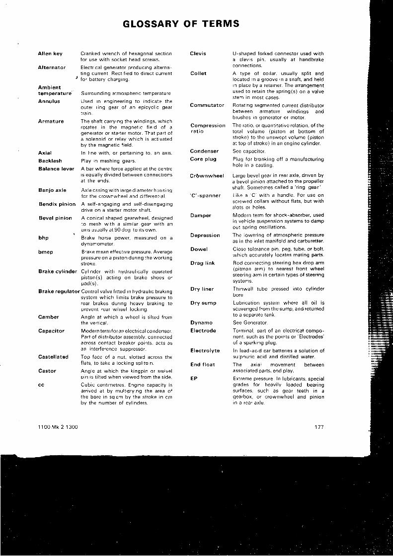
A l l en key C ranked w rench o f hexagona l sec t i onfor use wi th socket head screws.
A l t e rna to r E lec t r i ca l gene ra to rp roduc inga l t e rnat i ng cu r ren t . Rec t i f i ed t o d i r ec t cu r ren t
' for bat tery charging.
Amb ien tt empe ra tu re su r round ing a tmosphe r i c t empe ra tu re .
Annu lus Used i n eng inee r i ng t o i nd r ca te t heou te r r i ng gea r o f an ep i cyc l i c gea rt r a i n .
Armature The sha f t ca r r y i ng t he w ind ings , wh i chrotates in the magnet ic f ie ld of agenerator or star ter motor. That part ofa so leno id o r r e l ay wh i ch i s ac t i va tedby t he magne t i c f i e l d .
I n l i ne w i t h , o r pe r t a i n i ng I o , an ax r s .
P Iay i n mesh ing gea rs .
A bar where force appl ied at the centrei s equa l l y d i v i ded be tween connec t i onsa t t he ends .
Ban jo ax l e Ax le cas ing w i t h l a rge d i ame te r hous ingfo r t he c rownwhee l and d i f f e ren t i a l
Bend i x p i n i on A se l f - engag ing and se l f - d i sengag ingdr ive on a star ter motor shaf t .
Beve l p i n i on A con i ca l shaped gea rwhee l , des ignedto mesh w i t h a s im i l a r gea r w i t h anax i s usua l l y a1 90 deg . t o i t s own .
bhp '
Brake horse power, measured on adynamometer.
bmep Brake mean ef fect ive pressure. Averagep ressu re on a p i s t on du r i ng t he wo rk i ngstroke.
B rake cy l i nde r Cy l i nde r w i t h hyd rau l i ca l l y ope ra tedp i s ton (s ) ac t i ng on b rake shoes o rpad ( s ) .
Brake regulator Control valve f i t ted in hydraul ic brakingsystem which l imi ts brake pressure torea r b rakes du r i ng heavy b rak i ng t oprevent rear wheel locking.
Ang le a t wh i ch a whee l i s t i l t ed f r omthe vert ical .
Modern term f or an electr ical condenser.Part of d ist r ibutor assembly, connectedacross contact breaker points, acts asan inter ference suppressor.
Castel lated Top face of a nut , s lot ted across thef lats, to take a locking spl i tp in.
Cas to r Ang le a t wh i ch t he k i ngp in o r sw rve lp in is t i l ted when v iewed f rom the s ide.
cc Cub i c cen t ime t res . Eng ine capac i t y r sarr ived at by mul t ip ly ing the area oft he bo re i n sqcm by t he s t r oke i n cmby t he number o f c y l i nde rs .
1 1 0 0 M k 2 1 3 0 0
Ax ia l
Back lash
Balance lever
Camber
Capacitor
GTOSSARYO F T E R M S
Clev is
Co l le t
Commuta to r
Compress ionra t i o
Condense r
Co re p l ug
Crbwnwheel
' C ' - s p a n n e r
Damper
Dep ress ion
Dowe l
D r a g l i n k
Dry l i ne r
D ry sump
Dynamo
Electrode
E lec t ro l y t e
End f l oa t
E P
U-shaped forked connector used wi tha c l ev i s p i n , usua l l y a t handb rakeconnec t i ons .
A t ype o f co l l a r , usua l l y sp l i t andlocated in a groove in a snaf t , and heldin p lace by a reta iner. The arrangementused t o r e ta i n t he sp r i ng (s ) on a va l vestem in most cases.
Rotat ing segmented current d ist r ibutorbetween armature windings andbrushes in generator or motor.
The rat io, or quant i tat ive re lat ion, of thetotal volume (oiston at bot tom ofstroke) to the unswept volume (pistonat top of st roke) in an engine cyl inder.
See capacrtor .
Plug for b lanking o{ f a manufactur ingho le i n a cas t i ng .
Large bevel gear in rear axle, dr iven bya bevel p in ion at tached to the propel ler
shaf t . Somet imes cal led a ' r ing gear ' .
L i ke a 'C '
w i t h a hand le . Fo r use onscrewed col lars wi thout f lats, but wi ths l o t s o r ho les .
Modern term for shock-absorber, usedin vehic le suspension systems to dampou t sp r i ng osc i l l a t i ons .
The lower ing of atmospher ic pressureas in the in let mani fo ld and carburet ter .
Close to lerance pin, peg, tube, or bol t ,which accurately locates mat ing parts.
Rod connect ing steer ing box drop arm(pi tman arm) to nearest f ront wheelsteer ing arm in certa in types of steer ingsystems.
Thinwal l tube pressed into cyl inderDOre
Lub r i ca t i on sys tem whe re a l l o i l i sscavenged f rom the sump, and returnedto a separate tank.
See Generator .
Terminal , part of an electr ical compo-nent, such as the points or
'Electrodes'
o f a spa rk i ng p l ug .
I n l ead -ac rd ca r ba t t e r i es a so lu t i on o fsu lohu r i c ac i d and d i s t i l l ed wa te r .
The axia l movement betweenassociated parts, end play.
Extreme pressure. In lubr icants, specia lgrades for heavi ly loaded bear ingsurfaces, such as gear teeth in agearbox, or crownwheel and pin ionin a r ea r ax l e .
1 7 7
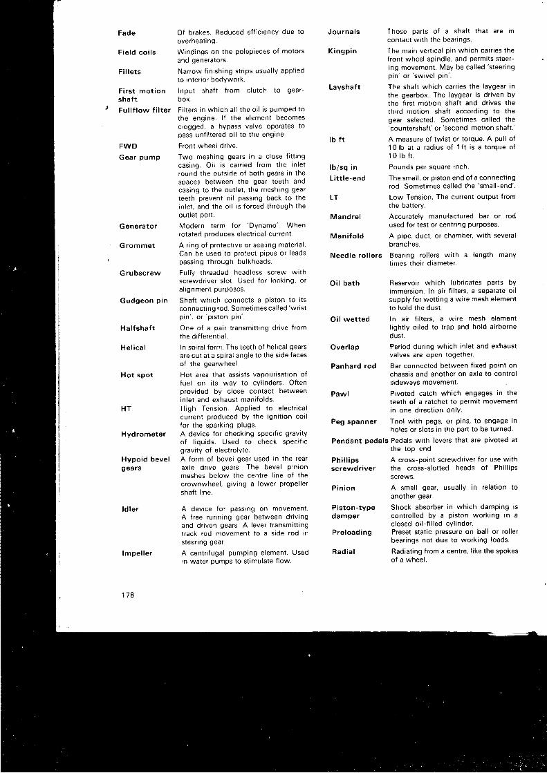
Fade
Fie ld co i l s
F i l le ts
' Fu l l f low f i l te r
FWD
Gear pump
Generator
Grommet
Grubscrew
Gudgeon p in
H a l fshaft
He l ica l
Hot spot
HT
Hydrometer
Hypoid bevelgears
l d l e r
lmpe l l e r
178
to inter ior bodYwork.
F i r s t mo t i on I npu t sha f t f r om c l u t ch t o gea r
shaf t box.
Of brakes. Reduced ef f ic iency due to
overheat i ng.
W ind ings on t he po lep ieces o f mo to r sand generators.
Na r row f i n i sh i ng s t r i ps usua l l y app l i ed
F i l t e r s i n wh i ch a l l t he o i l i s pumped t othe eng ine . l f t he e l emen t becomesclogged, a bypass valve operates topass un f i l t e red o i l t o t he eng ine .
Front wheel dr tve.
Two meshing gears in a c lose f i t t ingcas ing . O i l i s ca r r i ed f r om the i n l e tround the outs ide of both gears in thespaces between the gear teeth andcasjng to the out let , the meshing gear
teeth prevent o i l passing back to thein l e t . and t he o i l i s f o r ced t h rough t heout let port .
Mode rn t e rm fo r 'Dynamo ' .
Whenrotated oroduces electr ical current .
A r ing of protect ive or seal ing mater ia l .Can be used to protect p ipes or leadspass ing t h rough bu l kheads .
Ful fy threaded headless screw wi thscrewdr iver s lot . Used for locking, oral rgnment purposes.
Shaft which connects a p iston to i tsconnect ing rod. Somet imes cal led
'wr ist
p i n ' , o r ' p i s t on p i n ' .
One of a pair t ransmit t ing dr ive f romthe d i f f e ren t i a l .
In spira l form. The teeth of hel ical gearsare cut at a spira l angle to the s ide facesof the gearwheel .
Hot area that assists vapour isat ion offuel on i ts way to cYl inders. Oftenprovided by c lose contact betweeninlet and exhaust mani fo lds.H igh Tens ion . App l i ed t o e l ec t r i ca lcurrent produced by the igni t ion coi lfor the sparki ; rg p lugs.
A device for checking speci f ic gravi tyof l iquids. Used to check speci f icgravi ty of e lectro lyte.A form of bevel gear used in the rearax l e d r i ve gea rs . The beve l P in i onmeshes below the centre l ine of thecrownwheel , g iv ing a lower propel lershaf t l ine.
A device for passing on movement.A f ree running gear between dr iv ingand dr iven gears. A lever t ransmit t ingtrack rod movement to a s ide rod Insteer ing gear.
A centr i fugal pumping element. Usedin water oumDs to st imulate f low.
Those oarts of a shaf t that are incontact wi th the bear ings.
The ma in ve ( i ca l p i n wh i ch ca r r i es t hefront wheel spindle, and permits steer-ing movement. May be cal led
's teer ing
p in ' o r ' sw i ve l p i n ' .
The shaf t which carr ies the laygear inthe gearbox. The laygear is dr iven bythe f i rs t mot ion shaf t and dr ives thethi rd mot ion shaf t according to thegear selected. Somet imes cal led the'countershaf t '
or 'second mot ion shaf t . '
A measure of twist or torque. A pul l of10 lb a t a r ad ius o f 1 f t i s a t o rque o f1 0 l b f t .
Pounds per square inch.
The smal l , or p iston end of a connect ingrod . Some t imes ca l l ed t he
' sma l l - end ' .
Low Tension, The current output f romthe bat tery.
Accurately manufactured bar or rodused for test or centr ing purposes.
A pipe, duct , or chamber, wi th severalbranches.
Bear ing ro l lers wi th a length manyt imes their d iameter.
Reservoir which lubr icates parts byimmersion. In a i r f i l ters, a separate oi lsupply for wett ing a wire mesh elementto hold the dust .
Oi l wet ted In a i r f i l ters, a wire mesh elementl ight ly o i led to t rap and hold a i rbornedust .
Over lap Period dur ing which in let and exhaustvalves are open together.
Panhard rod Bar connected between f ixed point onchassis and another on axle to contro ls idewavs movement.
Pawl Pivoted catch which engages in theteeth of a ratchet to permit movementin one di rect ion onlv.
Peg spanner Tool wi th pegs, or pans, to engage Inholes or s lots in the part to be turned.
Pendant pedals Pedals wi th levers that are pivoted atthe top end.
A cross-ooint screwdr iver for use wi ththe cross-s lot ted heads of Phi l l ipsscrews.
A smal l gear, usual ly in re lat ion toanother gear.
Shock absorber in which damPing iscontro l led by a piston working in aclosed oi l - f i l led cyl inder.Preset stat ic oressure on bal l or ro l lerbear ings not due to working loads.
Radiat ing f rom a centre, l ike the spokeso f a whee l .
Jou rna l s
K i n g p i n
Layshaft
l b f t
lb /sq in
L i t t le -end
LT
Mandre l
Man i fo ld
Need le ro l le rs
Oi l ba th
P h i l l i p sscrewdriver
P in ion
Piston-typedamper
Pre load ing
R a d i a l
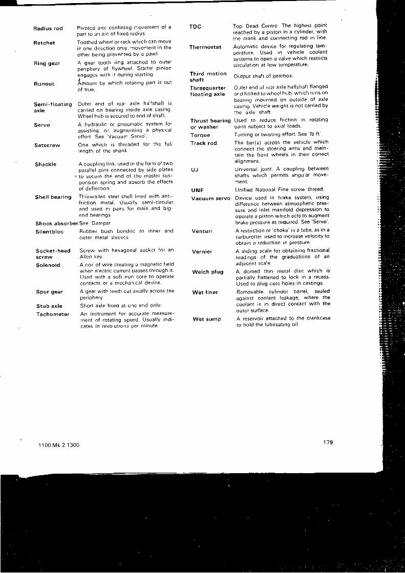
Rad ius rod P i vo ted a rm con f i n i ng movemen t o f a
Part to an arc of f ixed radiusTDC
Thermostat
Th i rd mot ionshaft
Th reeq uarterf loa t ing ax le
Thrus t bear ingor washer
Torque
Track rod
U J
U N F
Vacuum servo
Ventur i
Vern ie r
Welch p lug
Wet l iner
Wet sump
Top Dead Centre. The highest Porntreached bv a piston in a cyl inder, wi th
the crank and connect ing rod in l ine.
Automat ic device for regulat ing tem-
Derature. Used in vehic le coolant
systems to open a valve which restr ic ts
c i rculat ion at low temPerature.
Output shaf t of gearbox.
Ou te r end o f r ea r ax l e ha l f sha f t f l anged
and bo l t ed t o whee l hub . wh i ch runs on
bear ing mounted on outs ide of axlecasing. Vehic le weight is not carr ied by
the axle shaf t .
Used to reduce f r tc t ton in rotat ingparts subyect to axia l loads.
Turning or twist ing ef for t . See ' lb
f t "
The ba r ( s ) ac ross t he veh i c l e wh i ch
connec t t he s tee r i ng a rms and ma in -
ta in the f ront wheels in their correct
a l r gnmen t .
Universal io int . A coupl ing between
shafts which permits angular move-
men1 .
Un i f i ed Na t i ona l F i ne sc rew th read .
Device used in brake sYstem, usingdi f ference between atmospher ic pres-
sure and in let mani fo ld depression to
operate a piston which acts to augmentbrake pressure as required. See'Servo' .
A res t r i c t i on o r ' choke ' i n a t ube , as i n a
carburet ter , used to increase velocl ty to
obtain a reduct ion in Pressure.
A s l id ing scale for obtain ing f ract ional
readings of the graduat ions of an
adjacent scale.
A domed t h i n me ta l d i sc wh i ch i spart ia l ly f lat tened to lock in a recess
Used to p lug core holes in cast ings.
Removable cyl inder barrel , sealed
against coolant leakage, where the
coolant is in d i rect contact wi th the
outer surface.
A reservoir at tached to the crankcaseto ho ld t he l ub r i ca t i ng o i l .
179
Semi - f l oa t i ng Ou te r end o f r ea r ax l e ha l f sha f t i s
ax l e ca r r i ed on bea r rng i ns i de ax l e cas ing 'Wheel hub is secured to end of shaf t .
Servo A hydraul ic or pneumat ic system for
ass i s t i ng , o r , augmen t i ng a phys i ca l
ef for t . See 'Vacuum Servo' .
One wh i ch i s t h readed f o r t he f u l l
l eng th o f t he shank .
Shack te A coup l i ng l i n k , used i n t he f o rm o f twoparal le l p ins connected by s ide plates
r to secure the end of the master sus-pension spr ing and absorb the ef fectso f de f l ec t i on .
She l l bea r i ng Th inwa l l ed s tee l she l l l i ned w i t h an t i -f r i c t i on me ta l . Usua l l y sem i - c i r cu l a rano used i n Pa i r s f o r ma in and b i g -end bea r i ngs .
Shock abso rbe r See 'DamPer ' .
Ratchet
R ing gea r
R u n o u t
Setscrew
S i l en tb l oc
Socket-headscrew
So leno id
Spu r gea r
S tub ax l e
Tachometer
1 100 Mk 2 1300
Toothed wheel or rack which can move
in one d i r ec t i on on l y , movemen t i n t he
other being prevented bY a Pawl
A gear tooth r ing at tached to outerper iphery of f lywheel . Star ter p inron
engages w r th i t du i l ng s ta r t i ng .
A.orn, by which rotat ing Part is oul
o f t r ue .
Rubbe r bush bonded t o i nne r andouter metal s leeves.
Sc rew w i t h hexagona l socke t f o r anA l l en key .
A co i l o f w i r e c rea t i ng a magne t i c f i e l dwhen electr ic current passes through i t .
Used wi th a sof t i ron core to operatecon tac t s o r a mechan i ca l dev i ce .
A gear wi th teeth cut axia l ly across thepen pnery.
Sho r t ax l e f i xed a t cne end on lY .
An instrument for accurate measure-men t o f r o ta t i ng speed . Usua l l y i nd i -ca tes i n r evo lu t i ons Pe r m inu te .
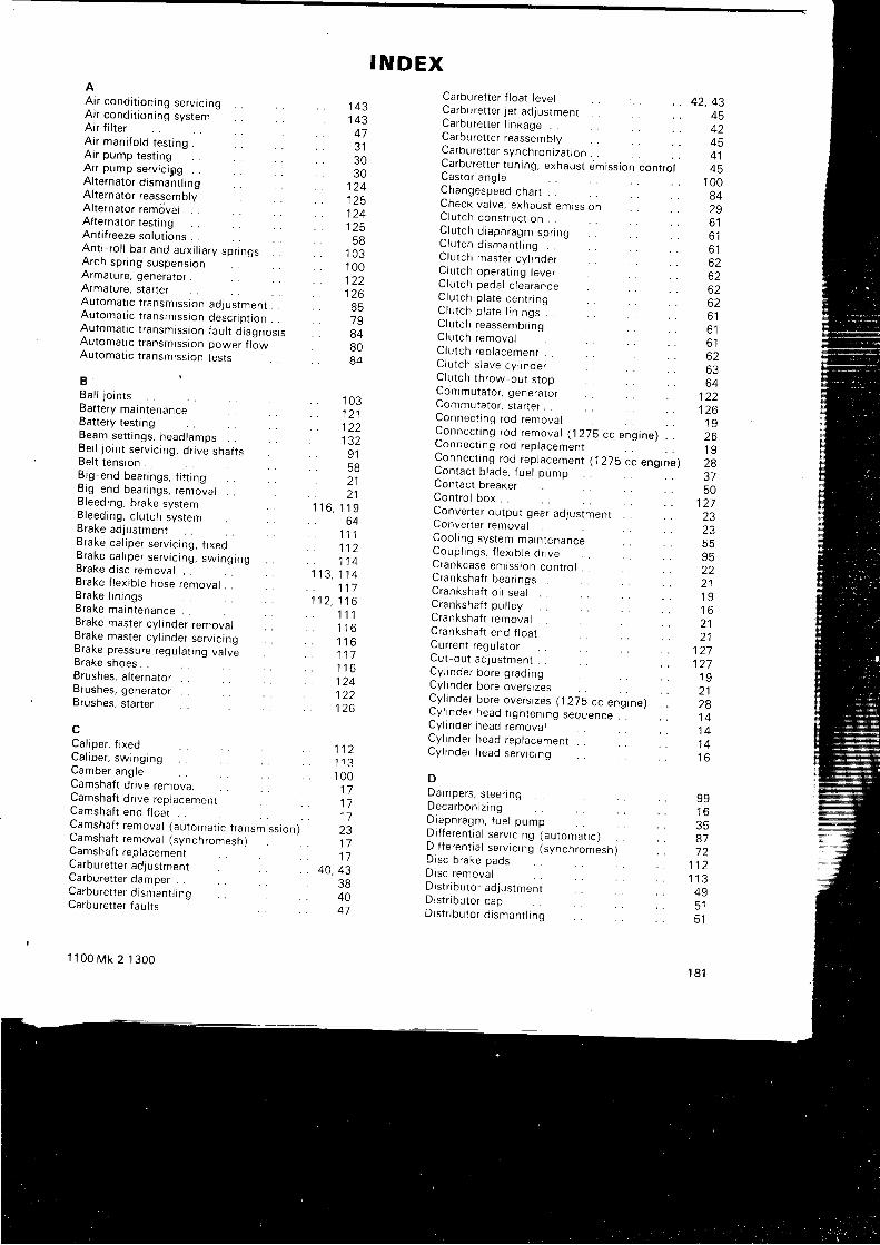
I N D E XAA i r cond i t i on i ng se rv i c i ngAir condi t ioning systemAir f i l terAir mani fo ld test ing .A i r pump tes t i ngAir pump serv ic igg . .Al ternator d ismant l ingAl ternator reassemblyAl ternator rem6valAl ternator test ingAnt i f reeze solut ions . .An t i - r o l l ba r and aux i l i a r y sp r i ngs . .Arch spr ing suspensionArmature, generatorArmature, star terAutomat ic t ransmission aojUstment . .Au toma t i c t r ansm iss i on desc r i p t i on . .Au toma t i c t r ansm iss i on f au l t d i agnos i sAu toma t i c t r ansm iss i on power f l owAutomat ic t ransmission tests
B .Ba l l j o i n t sBattery maintenanceBattery test ingBeam se t t i ngs , head lamps . .Be l l j o i n t se r v i c i ng . d r i ve sha f t sBel t tension . .
! i g end bea r i ngs , f i t r i ng6 rg -end bea r i ngs , r emova lBleeding, brake systemB leed ing , c l u t ch sys temBrake adjustmentB rake ca l i pe r se r v i c i ng , f i xedBrake ca l i pe r se r v i c i ng , sw rng ingbraKe dtsc removal . .Brake f lex ib le hose removal . .B rake I i n i ngsBrake ma in tenance . .Brake master cy l inder removalBrake master cy l inder servtcrngBrake p ressu re regu la t i ng va l ve6 raKe shoes . .B rushes , a l t e rna to r . .Brushes, generatorBrushes, Jtar ter
cCal iper, f rxedCa l i pe r , sw rng ingCamber ang leCamshaft dr ive removalCamshaft dr ive replacemenrCamshaft end f loat . .Camsha f t r emova l ( au toma t i c t r ansm iss ron )Camsha f t r emwa l ( synch romesn ;Camshaft replacementCarburet ter adjustmentCarburet ter damper . .Ca rbu re t t e r d i sman t l i nqCarburet ter faul ts
1 1 0 0 M k 2 1 3 0 0
143. . 1 4 3
473 130
. . 3 0, t z l
1251 2 4t z 3E A
. 1 0 31 0 01 2 2126
798480
. . 8 4
1 0 31211 2 21 3 2
' 9 158) 1
) 1' r 1 6 , 1 1 9
o4. 1 1 1. . 1 1 2. . 1 1 41 1 3 , 1 1 4
1 1 71 1 2 , 1 1 6
1 1 11 1 6t t o
1 1 11 1 61 2 41 2 2
. t z o
1 1 21 1 31 0 01 11 71 l231 71 7
40, 4338404 l
Carburet ter f loat levelCarburet ter jet adjustmentCa rbu re t t e r l i n kage . .Carburet ter reass-emblyC a r b u r e t t e r s y n c h r o n i z a t r o n . . . .Ca rbu re t t e r t un i ng . exhaus t em iss i on con t ro lCas to r ang leChangesp-eed chart . .Check va l ve , exhaus t em iss i onC lu t ch cons t ruc t i on . .C lu t ch d i aph ragm spnngu t u t c n d r s m a n i l t n g . .C lu t ch mas te r cy l i nde rC lu t ch ope ra t i ng l eve rC lu t ch peda l c l ea ranceC lu t ch p l a te cen t r i ngC lu t ch p l a te l i n i ngs . .Clutch reassembl lng . .C lu t ch remova l . .C lu t ch rep lacemen t . .C lu t ch s l ave cy l i nde rC lu t ch t h row-ou t s t opCommutator , generatorCommutator , s tar ter . .Connec t i ng rod remova lConnec t i ng rod remova l ( j 275 cc ung ine l . .Lonnec t t ng rod rep lacemen t .Connec t i ng rod rep lacemen t ( 1275 cc eng ine )Con tac t b l ade , f ue l pumpContact breakerControl boxConverter output gear aalusiment . . . .LOnverter removalCoo l i ng sys tem ma in tenanceCoup l i ngs , f l e x i b l e d r i veCrankcase em iss ron con t ro l .C ranksha f t bea r i ngs . .C ranksha f t o i l sea l .C ranksha f t pu l l eyCranksha f t r emova l . .C ranksha f t end f l oa tCu r ren t r egu la to rCut-out aJjustment . .Cy l i nde r bo re g rad inguy Inoe r bo re ove f s i zesCy f i nde r bo re ove rs r zes (1275 cc eng ine ) . .
: y i l noe r head t r gh ten ing sequence . .
uy i l noe r nead remova lCy l i nde r head rep lacemen tCy l r nde r head se rv r c i ng
DDampers , s t ee r i ngDeca rbon i z i ngD iaph ragm, f ue l pumpD i f f e ren t i a l se r v i c i ng (au toma t i c )D i f f e ren t i a l se r v i c i ng ( synch romesh )D i sc b rake padsDrsc remova lD i s t r i bu to r ad jus tmen tD i s t r i bu to r capD is t r i bu to r d i sman t l i ng
42, 434542454 145
1 0 084296 1o l
o t
62626262o l
o l
6 1626364
1 2 2t z o
1 9261 9283750
1 2 7) 2
23
2 11 91 6z l
1 a
1 2 71 2 7'l 92 1281 41 41 41 6
99t o
877 2
1 1 2t t J
495 15 1
1 8 1
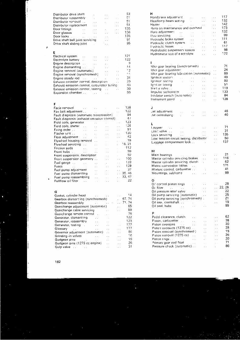
Dis t r i bu to r d r i ve sha f tDistr ibutor reassemblyDistr ibutor removal . .D i s t r i bu to r r ep lacemen tDoo r f i t t i ngsDoor g lassesDoor locksDr i ve sha f t be l l j o i n t se r v i c i ngDr i ve sha f t s l i d i ng j o i n t
EE lec t r i ca l s ys temElectro lyte bat teryEng ine desc r i p t i on . .Eng ine d i sman t l i ng . .Eng ine remova l ( au toma t i c )Eng ine remova l ( synch romesh ) . .Eng ine s teady rodExhaus t em iss i on con t ro l , desc r i p t i onExhaus t em iss i on con t ro l , ca rbu re t t e r t un i ngExhaus t em iss i on con t ro l , t es t r ngExpans ron chamber . .
FFacia removalFan bel t adjUstmentFau l t d i agnos i s ( au toma t i c t r ansm iss ron )Fau l t d i agnos i s ( exhaus t em iss ron con t ro l )F i e l d co i l s , gene ra to rFie ld coi ls , s tar terF i r i ng o rde r . .F l ashe r un i tF l oa t ad jus tmen tF l ywhee l hous ing remova l . .F lywheel serv ic ingF r i c t i on padsF ron t hubs . .F ron t suspens ion . desc r i p t i onFront suspension geometryFue l gauge . .FusesFue l pump adJus tmen tFue l pump d i sman t l i ngFue l pump reassemb l i ngFu l l f l ow o i l f i l t e r
GGaske t , c y l i nde r headGearbox d i sman t l i ng ( synch romesh )
Gearbox reassemblyGea rchange ad jus tmen t ( au toma t i c )
Gea rchange cab le se rv i c i ngGearchange remote contro l . .Gene ra to r , d i sman t l i ngGenerator , reassemblyGenerator , test ingG lossaryGovernor adjustment (automat ic)
G r i nd ing - i n va l ves .Gudgeon p i nsGudgeon p i ns ( 1 275 cc enE ine )Gu lp va l ve
182
533 l
5 l
3 l
1 3 51 3 61 3 59 19 5
1211 2 2
91 41 21 1J I
2943305 5
1 3 81 2 28441
123t z o
5 11 3 0421 B
1 8 , 2 11 1 29992
1 0 0I J J
129
35, 4633,47
22
1 46 7 , 7 47 1 , 7 4
B5B 97 6
1 2 21 2 31 2 21 1 786t o
1 926J I
1 1 713214217313299
1 1 16 1
1 1 798
1 2 2
7 124
8949qo
511 1 91 3 384
t J 6
4540
1 a
3 1
50137
2 11 1 6oz
1 7 14 1q q
282 2 , 2 6
22
211 999
HHandb rake ad lus tmen tHead lamp beam se t t i ngH ea le rH in t s on ma in tenance and ove rhau lHo rn ad jus tmen tHub se rv i c i ngHyd rau l i c b rake sys temHyd rau l r c c l u t ch sys temHyd rau l i c hosesHydrolast ic suspension systemHydrometer test of e lectro lYte
Il d l e r gea r bea r i ng ( synch romesh )l d l e r gea r ad jus tmen tl d l e r gea r bea r rng l ub r i ca t i on (au toma t i c )l g n r t r o n s y s t e ml g n i t r o n t e s t r n gl g n i l g n 1 1 6 1 n 9I n e r t r a v a l v elmpu l se t achome te rI nh ib i t o r sw r t ch (au toma t i c )I ns t r umen t pane l
Je t ad lus tmen tJe t cen t ra l i z i ng
LLaygearL rm i t va l ve . .Lock se rv l c i ngLow-tension c i rcui t test ing, d ist r ibutorLuggage compartment loc l ( . .
MMa in bea r i ngsMas te r cy l i nde r se r v i c rng b rakesMas te r cy l i nde r se r vac ing , c l u t chMe t r i c - conve rs i on t ab lesMixture contro l , carburet terMoun t i ngs , sub f rame
oOi l con t ro l p i s t on r i ngsO i l f r l t e rO i l p ressu re re l i e f va l veO i l pump se rv i c i ng (au toma t i c )
O i l pump se rv i c i ng ( synch romesh ) . .
O i l sea l , c ranksha f t . .O i l sea l , hubs
PPeda l c l ea rance , c l u t chP i s ton , ca rbu re t t e r . .Piston overs izes . .P i s t on ove rs i zes (1275 cc ) . .P r s ton remova l ( synch romesh )P i s t on remova l ( 1275 cc )P i s ton r i ngsP r ima ry gea r end f l oa tP ressu re check (au toma t i c ) . .
oz3820281 q
26207 16 b
Pressu re f a i l u re sw i t chPressure regulat ing valvePushrod removal and replacement . .
RRack, steer ingRadiator removal and replacement . .Rear brake servrc lngRea r hubsRear suspension . .Regu la to r un i tRocke r c l ea ranceRocker shaf t assemblyRocker shaf t assembly (1275 cc)Rocke r se t t i ng , f ue l pump
sSealed beam headlampsSeat bel tsSelector forks and rodsS lave cy l i nde r , c l u t chS low- runn ing ad jus tmen t , ca rbu re t t e rSpa rk i ng p l ugsSpeci f ic gravi ty, ant i f reeze . .Speci f ic gravi ty, e lectro lyte . .Stal l speed check (automatrc)Star ter motor serv ic ingStarter motor test ingS ta t i c i gn i t i on t im ingSteer ing anglesSteer ing bal l jo ints . .Steer ing column removalSteer ing column ref i t t ingSteer ing lock and igni t ion swi tchSteer ing rack adjustment . .Steer ing rack serv ic ingSteer ing wheelS t roboscop i c i gn i t i on t im ingSub { rames and moun t i ngsSuspension system, descr ipt ionSuspens ion se rv i c i ngSw ive l hub i nc l i na t i onSynchromesh t ransmission . .Synchroniz ing twin carburet ters
1' r 00 Mk 2 1300
1 1 91 1 1
. 1 4
. 9 8
. 5 11 1 4
. 9 998
. 1 2 722
. t o
. t o
31
. | 5 2
. 137
. 6 9
. 6 3405258
. 1 1 486
r z c , t J J
. t z 3
. 5 l
1 0 0. '1 08
1 0 6. 1 0 6
1 0 91 0 8
. 1011 0 5
. 5 2
. 9 9
. 9 89B
1 0 0. 6 7. 4 1
1 3 31 1 81471 3 3594 J
64t o
1 6t o
c l
1 0 81 1 16279
1541 0 9
2 3 , 2 469
9 1
12049'l 6z o
361 62223t o
1371 ) E
I J J
58t J b
1 3 61 3 0t 3 0
TTachome te r . impu l se t ypeTandem mas te r cy l i nde r , b rakesTechn i ca l Da taT o m n o r e r r r r o n e r r n o
The rmos ta t t es t r ng .Th ro t t l e damper ( 1275 cc )Th row-ou t s t op , c l u t chT imrng cha in cove rT im ing cha in sp rocke tT im ing marks , camsha f tT im ing marks . i gn i t i onT ^ a - ^ , ' r 1 . l i ' , c i m o n t
Topp ing -up mas te r cy l i nde r , b rakes . .Topp rng -up mas te r cy l i nde r , c l u t ch . .Torque converterTo rque w rench se t t r ngsT rack ing f r on t whee l sT ransm iss i on se rv i c rng (au toma t i c ) . .T ransm iss i on se rv i c i ng ( synch romesh )T r im pad remova l . doo r
UUnrve rsa l coup l r ngs
Vacuum se rvo un i tVacuum t im ing con t ro lVa l ve se rv i c i ngVa l ve se rv i c i ng (1215 ccJVa l ves . f ue l pumpVa l ve gu idesVa l ve rocke r ad jus tmen tVa l ve t im ing gea r ( au toma t i c )Va l ve t im ing gea r ( synch romesh )Ven t i l a t o r r emova lVol tage regulator adjustment\ / n l r e n o c r e h i l i z o r
WWater c i rcu lat ion systemWate r pump se rv i c i ngWindow g lass remova lW indow w inde rsWrpe r mo to r se r v i c i ngWi r i ng d i ag rams . .
1 8 3