
© MasterSeries PowerPad - Project Title Joints Output - Amazon Simple … · 2017-06-12 · ©...
66
© MasterSeries PowerPad - Project Title Joints Output.doc © Civil and Structural Computer Services Limited, 1 Circular Road, Newtownabbey, Co. Antrim BT37 0RA, Tel : 028 9036 5950 Fax : 028 9036 5102 MASTERSERIES MOMENT & SIMPLE CONNECTIONS SAMPLE OUTPUT The Following Output is from the Moment and simple connections Programs Contents Full output 2 Eaves Connection (Full output) 16 Apex Connection (Full output) 20 Slab Base Plate (Full output) 22 Column Splice (Full output) 25 Beam to Column Fin-Plate (Full output) 32 Reduced Output Eaves Connection 37 Summary Output for 17 Connections 58 Graphics Only for 17 Connections
Transcript of © MasterSeries PowerPad - Project Title Joints Output - Amazon Simple … · 2017-06-12 · ©...
© MasterSeries PowerPad - Project Title Joints Output.doc
© Civil and Structural Computer Services Limited, 1 Circular Road, Newtownabbey, Co. Antrim BT37 0RA, Tel : 028 9036 5950 Fax : 028 9036 5102
MMAASSTTEERRSSEERRIIEESS
MMOOMMEENNTT && SSIIMMPPLLEE CCOONNNNEECCTTIIOONNSS
SSAAMMPPLLEE OOUUTTPPUUTT
The Following Output is from the Moment and simple connections Programs
Contents Full output
2 Eaves Connection (Full output) 16 Apex Connection (Full output) 20 Slab Base Plate (Full output) 22 Column Splice (Full output) 25 Beam to Column Fin-Plate (Full output) 32 Reduced Output Eaves Connection 37 Summary Output for 17 Connections 58 Graphics Only for 17 Connections
© MasterSeries PowerPad - Project Title Joints Output.doc
_MasterSeries User Company 1 Circular Road
Newtownabbey
Co. Antrim, BT37 0RA
Tel: (028) 9036 5950 Fax: (028) 9036 5102
Job ref : Job Ref
Sheet : Sheet Ref / 2 -
Made By :
Date : 19 Jun 2008/ Version 2007.17
Checked :
Approved :
© Civil and Structural Computer Services Limited, 1 Circular Road, Newtownabbey, Co. Antrim BT37 0RA, Tel : 028 9036 5950 Fax : 028 9036 5102
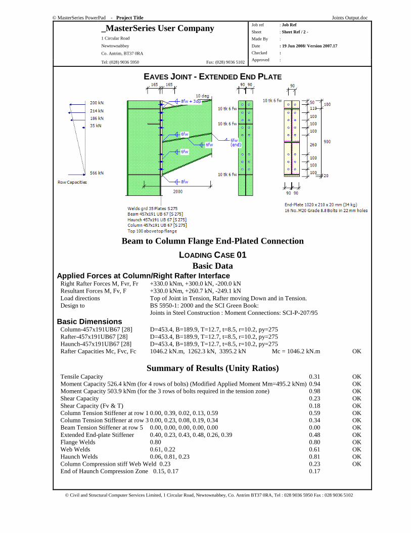
EAVES JOINT - EXTENDED END PLATE
Beam to Column Flange End-Plated Connection
LOADING CASE 01 Basic Data
Applied Forces at Column/Right Rafter Interface Right Rafter Forces M, Fvr, Fr +330.0 kNm, +300.0 kN, -200.0 kN Resultant Forces M, Fv, F +330.0 kNm, +260.7 kN, -249.1 kN Load directions Top of Joint in Tension, Rafter moving Down and in Tension. Design to BS 5950-1: 2000 and the SCI Green Book: Joints in Steel Construction : Moment Connections: SCI-P-207/95
Basic Dimensions Column-457x191UB67 [28] D=453.4, B=189.9, T=12.7, t=8.5, r=10.2, py=275 Rafter-457x191UB67 [28] D=453.4, B=189.9, T=12.7, t=8.5, r=10.2, py=275 Haunch-457x191UB67 [28] D=453.4, B=189.9, T=12.7, t=8.5, r=10.2, py=275 Rafter Capacities Mc, Fvc, Fc 1046.2 kN.m, 1262.3 kN, 3395.2 kN Mc = 1046.2 kN.m OK
Summary of Results (Unity Ratios) Tensile Capacity 0.31 OK Moment Capacity 526.4 kNm (for 4 rows of bolts) (Modified Applied Moment Mm=495.2 kNm) 0.94 OK Moment Capacity 503.9 kNm (for the 3 rows of bolts required in the tension zone) 0.98 OK Shear Capacity 0.23 OK Shear Capacity (Fv & T) 0.18 OK Column Tension Stiffener at row 1 0.00, 0.39, 0.02, 0.13, 0.59 0.59 OK Column Tension Stiffener at row 3 0.00, 0.23, 0.08, 0.19, 0.34 0.34 OK Beam Tension Stiffener at row 5 0.00, 0.00, 0.00, 0.00, 0.00 0.00 OK Extended End-plate Stiffener 0.40, 0.23, 0.43, 0.48, 0.26, 0.39 0.48 OK Flange Welds 0.80 0.80 OK Web Welds 0.61, 0.22 0.61 OK Haunch Welds 0.06, 0.81, 0.23 0.81 OK Column Compression stiff Web Weld 0.23 0.23 OK End of Haunch Compression Zone 0.15, 0.17 0.17
© MasterSeries PowerPad - Project Title Joints Output.doc
_MasterSeries User Company 1 Circular Road
Newtownabbey
Co. Antrim, BT37 0RA
Tel: (028) 9036 5950 Fax: (028) 9036 5102
Job ref : Job Ref
Sheet : Sheet Ref / 3 -
Made By :
Date : 19 Jun 2008/ Version 2007.17
Checked :
Approved :
© Civil and Structural Computer Services Limited, 1 Circular Road, Newtownabbey, Co. Antrim BT37 0RA, Tel : 028 9036 5950 Fax : 028 9036 5102
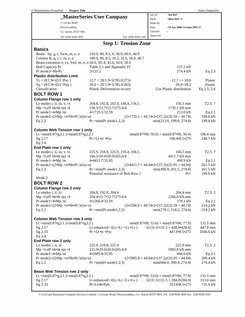
Step 1: Tension Zone Basics Beam bp, g, t, Sww, m, e, n 210.0, 90, 8.5, 6, 36.0, 60.0, 44.9 Column B, g, t, r, m, e, n 189.9, 90, 8.5, 10.2, 32.6, 50.0, 40.7 Beam extension x, ex, Swf, m, e, n 50.0, 50, 8, 43.6, 50.0, 50.0 Bolt Capacity Pt ' Table 2.1 and Appendix IV 137.2 kN Pr mode3=Nb•Pt ' 2•137.2 274.4 kN Eq 2.3 Plastic distribution Limit Tc < Ø/1.9•√(Uf /Pyc ) 12.7 < 20/1.9•√(785.0/275) 12.7 <= 18.0 Plastic Tp < Ø/1.9•√(Uf /Pyp ) 20.0 < 20/1.9•√(785.0/265) 20.0>18.3 Elastic Classification Plastic Deformation occurs. Use Plastic distribution Eq 2.5; 2.6
BOLT ROW 1 Column Flange row 1 only Le modes i, ii, iii, v, vi 204.8, 192.8, 202.9, 146.4, 156.5 156.5 mm T2.5: 7 Mp =Leff •tk•tk •py /4 156.5•12.7•12.7•275.0/4 1735.1 kN.mm Pr mode1=4•Mp /m 4•1735.1/32.59 213.0 kN Eq 2.1 Pr mode2=(2•Mp +n•Nb•Pt ')/(m+n) (2•1735.1 + 40.74•2•137.2)/(32.59 + 40.74) 199.8 kN Eq 2.2 Pr =min(Pr mode1,2,3) min(213.0, 199.8, 274.4) 199.8 kN Column Web Tension row 1 only Lt =min(0.87•g,L1 )+min(0.87•g,L2 ) min(0.87•90, 50.0) + min(0.87•90, 56.4) 106.4 mm fig 2.17 Pt =Lt •tc •Pyc 106.4•8.5•275 248.7 kN Eq 2.4 End Plate row 1 only Le modes i, ii, iii, v, vi 225.9, 218.8, 225.9, 159.4, 166.5 166.5 mm T2.5: 7 Mp =Leff •tk•tk •py /4 166.5•20.0•20.0•265.0/4 4411.7 kN.mm Pr mode1=4•Mp /m 4•4411.7/35.95 490.9 kN Eq 2.1 Pr mode2=(2•Mp +n•Nb•Pt ')/(m+n) (2•4411.7 + 44.94•2•137.2)/(35.95 + 44.94) 261.5 kN Eq 2.2 Pr =min(Pr mode1,2,3) min(490.9, 261.5, 274.4) 261.5 kN Potential resistance of Bolt Row 1 Pr1 199.8 kN Mode 2
BOLT ROW 2 Column Flange row 2 only Le modes i, ii, iii 204.8, 192.8, 204.4 204.4 mm T2.5: 2 Mp =Leff •tk•tk •py /4 204.4•12.7•12.7•275.0/4 2266.0 kN.mm Pr mode1=4•Mp /m 4•2266.0/32.59 278.1 kN Eq 2.1 Pr mode2=(2•Mp +n•Nb•Pt ')/(m+n) (2•2266.0 + 40.74•2•137.2)/(32.59 + 40.74) 214.2 kN Eq 2.2 Pr =min(Pr mode1,2,3) min(278.1, 214.2, 274.4) 214.2 kN Column Web Tension row 2 only Lt =min(0.87•g,L1 )+min(0.87•g,L2 ) min(0.87•90, 53.6) + min(0.87•90, 77.9) 131.5 mm fig 2.17 Lt enhanced=√(Lt •Lt +Ls •Ls ) √(131.5•131.5 + 428.0•428.0) 447.8 mm fig 2.33 Pt =Lt •tc •Pyc 447.8•8.5•275 1046.6 kN Eq 2.4 End Plate row 2 only Le modes i, ii, iii 225.9, 218.8, 225.9 225.9 mm T2.5: 2 Mp =Leff •tk•tk •py /4 225.9•20.0•20.0•265.0/4 5985.8 kN.mm Pr mode1=4•Mp /m 4•5985.8/35.95 666.0 kN Eq 2.1 Pr mode2=(2•Mp +n•Nb•Pt ')/(m+n) (2•5985.8 + 44.94•2•137.2)/(35.95 + 44.94) 300.4 kN Eq 2.2 Pr =min(Pr mode1,2,3) min(666.0, 300.4, 274.4) 274.4 kN Beam Web Tension row 2 only Lt =min(0.87•g,L1 )+min(0.87•g,L2 ) min(0.87•90, 53.6) + min(0.87•90, 77.9) 131.5 mm fig 2.17 Lt enhanced=√(Lt •Lt +Ls •Ls ) √(131.5•131.5 + 284.0•284.0) 313.0 mm fig 2.33 Pt=Lt•tb•Pyb 313.0•8.5•275 731.6 kN
© MasterSeries PowerPad - Project Title Joints Output.doc
_MasterSeries User Company 1 Circular Road
Newtownabbey
Co. Antrim, BT37 0RA
Tel: (028) 9036 5950 Fax: (028) 9036 5102
Job ref : Job Ref
Sheet : Sheet Ref / 4 -
Made By :
Date : 19 Jun 2008/ Version 2007.17
Checked :
Approved :
© Civil and Structural Computer Services Limited, 1 Circular Road, Newtownabbey, Co. Antrim BT37 0RA, Tel : 028 9036 5950 Fax : 028 9036 5102
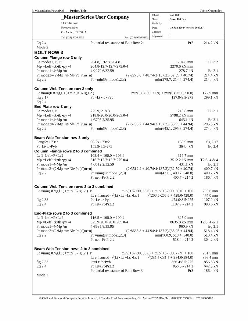
Eq 2.4 Potential resistance of Bolt Row 2 Pr2 214.2 kN Mode 2
BOLT ROW 3 Column Flange row 3 only Le modes i, ii, iii 204.8, 192.8, 204.8 204.8 mm T2.5: 2 Mp =Leff •tk•tk •py /4 204.8•12.7•12.7•275.0/4 2270.6 kN.mm Pr mode1=4•Mp /m 4•2270.6/32.59 278.7 kN Eq 2.1 Pr mode2=(2•Mp +n•Nb•Pt ')/(m+n) (2•2270.6 + 40.74•2•137.2)/(32.59 + 40.74) 214.4 kN Eq 2.2 Pr =min(Pr mode1,2,3) min(278.7, 214.4, 274.4) 214.4 kN Column Web Tension row 3 only Lt =min(0.87•g,L1 )+min(0.87•g,L2 ) min(0.87•90, 77.9) + min(0.87•90, 50.0) 127.9 mm fig 2.17 Pt =Lt •tc •Pyc 127.9•8.5•275 299.1 kN Eq 2.4 End Plate row 3 only Le modes i, ii 225.9, 218.8 218.8 mm T2.5: 1 Mp =Leff •tk•tk •py /4 218.8•20.0•20.0•265.0/4 5798.2 kN.mm Pr mode1=4•Mp /m 4•5798.2/35.95 645.1 kN Eq 2.1 Pr mode2=(2•Mp +n•Nb•Pt ')/(m+n) (2•5798.2 + 44.94•2•137.2)/(35.95 + 44.94) 295.8 kN Eq 2.2 Pr =min(Pr mode1,2,3) min(645.1, 295.8, 274.4) 274.4 kN Beam Web Tension row 3 only Lt=g/2•1.73•2 90/2x1.73x2 155.9 mm fig 2.17 Pt=Lt•tb•Pyb 155.9•8.5•275 364.4 kN Eq 2.4 Column Flange rows 2 to 3 combined Leff=Le1+P+Le2 108.4 + 100.0 + 108.4 316.7 mm Mp =Leff •tk•tk •py /4 316.7•12.7•12.7•275.0/4 3512.2 kN.mm T2.6: 4 & 4 Pr mode1=4•Mp /m 4•3512.2/32.59 431.1 kN Eq 2.1 Pr mode2=(2•Mp +n•Nb•Pt ')/(m+n) (2•3512.2 + 40.74•4•137.2)/(32.59 + 40.74) 400.7 kN Eq 2.2 Pr =min(Pr mode1,2,3) min(431.1, 400.7, 548.8) 400.7 kN Pr net=Pr-Pr2,2 400.7 - 214.2 186.4 kN Column Web Tension rows 2 to 3 combined Lt =min(.87•g,l1 )+min(.87•g,l2 )+P min(0.87•90, 53.6) + min(0.87•90, 50.0) + 100 203.6 mm Lt enhanced=√(Lt •Lt +Ls •Ls ) √(203.6•203.6 + 428.0•428.0) 474.0 mm fig 2.33 Pt=Lt•tc•Pyc 474.0•8.5•275 1107.9 kN Eq 2.4 Pt net=Pt-Pr2,2 1107.9 - 214.2 893.6 kN End-Plate rows 2 to 3 combined Leff=Le1+P+Le2 116.5 + 100.0 + 109.4 325.9 mm Mp =Leff •tk•tk •py /4 325.9•20.0•20.0•265.0/4 8635.8 kN.mm T2.6: 4 & 1 Pr mode1=4•Mp /m 4•8635.8/35.95 960.9 kN Eq 2.1 Pr mode2=(2•Mp +n•Nb•Pt ')/(m+n) (2•8635.8 + 44.94•4•137.2)/(35.95 + 44.94) 518.4 kN Eq 2.2 Pr =min(Pr mode1,2,3) min(960.9, 518.4, 548.8) 518.4 kN Pr net=Pr-Pr2,2 518.4 - 214.2 304.2 kN Beam Web Tension rows 2 to 3 combined Lt =min(.87•g,l1 )+min(.87•g,l2 )+P min(0.87•90, 53.6) + min(0.87•90, 77.9) + 100 231.5 mm Lt enhanced=√(Lt •Lt +Ls •Ls ) √(231.5•231.5 + 284.0•284.0) 366.4 mm fig 2.33 Pt=Lt•tb•Pyb 366.4•8.5•275 856.5 kN Eq 2.4 Pt net=Pt-Pr2,2 856.5 - 214.2 642.3 kN Potential resistance of Bolt Row 3 Pr3 186.4 kN Mode 2
© MasterSeries PowerPad - Project Title Joints Output.doc
_MasterSeries User Company 1 Circular Road
Newtownabbey
Co. Antrim, BT37 0RA
Tel: (028) 9036 5950 Fax: (028) 9036 5102
Job ref : Job Ref
Sheet : Sheet Ref / 5 -
Made By :
Date : 19 Jun 2008/ Version 2007.17
Checked :
Approved :
© Civil and Structural Computer Services Limited, 1 Circular Road, Newtownabbey, Co. Antrim BT37 0RA, Tel : 028 9036 5950 Fax : 028 9036 5102
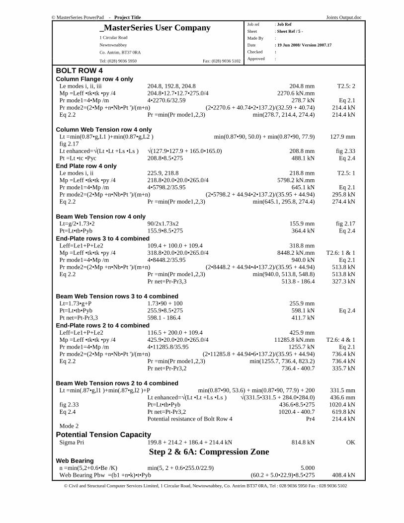
BOLT ROW 4 Column Flange row 4 only Le modes i, ii, iii 204.8, 192.8, 204.8 204.8 mm T2.5: 2 Mp =Leff •tk•tk •py /4 204.8•12.7•12.7•275.0/4 2270.6 kN.mm Pr mode1=4•Mp /m 4•2270.6/32.59 278.7 kN Eq 2.1 Pr mode2=(2•Mp +n•Nb•Pt ')/(m+n) (2•2270.6 + 40.74•2•137.2)/(32.59 + 40.74) 214.4 kN Eq 2.2 Pr =min(Pr mode1,2,3) min(278.7, 214.4, 274.4) 214.4 kN Column Web Tension row 4 only Lt =min(0.87•g,L1 )+min(0.87•g,L2 ) min(0.87•90, 50.0) + min(0.87•90, 77.9) 127.9 mm fig 2.17 Lt enhanced=√(Lt •Lt +Ls •Ls ) √(127.9•127.9 + 165.0•165.0) 208.8 mm fig 2.33 Pt =Lt •tc •Pyc 208.8•8.5•275 488.1 kN Eq 2.4 End Plate row 4 only Le modes i, ii 225.9, 218.8 218.8 mm T2.5: 1 Mp =Leff •tk•tk •py /4 218.8•20.0•20.0•265.0/4 5798.2 kN.mm Pr mode1=4•Mp /m 4•5798.2/35.95 645.1 kN Eq 2.1 Pr mode2=(2•Mp +n•Nb•Pt ')/(m+n) (2•5798.2 + 44.94•2•137.2)/(35.95 + 44.94) 295.8 kN Eq 2.2 Pr =min(Pr mode1,2,3) min(645.1, 295.8, 274.4) 274.4 kN Beam Web Tension row 4 only Lt=g/2•1.73•2 90/2x1.73x2 155.9 mm fig 2.17 Pt=Lt•tb•Pyb 155.9•8.5•275 364.4 kN Eq 2.4 End-Plate rows 3 to 4 combined Leff=Le1+P+Le2 109.4 + 100.0 + 109.4 318.8 mm Mp =Leff •tk•tk •py /4 318.8•20.0•20.0•265.0/4 8448.2 kN.mm T2.6: 1 & 1 Pr mode1=4•Mp /m 4•8448.2/35.95 940.0 kN Eq 2.1 Pr mode2=(2•Mp +n•Nb•Pt ')/(m+n) (2•8448.2 + 44.94•4•137.2)/(35.95 + 44.94) 513.8 kN Eq 2.2 Pr =min(Pr mode1,2,3) min(940.0, 513.8, 548.8) 513.8 kN Pr net=Pr-Pr3,3 513.8 - 186.4 327.3 kN Beam Web Tension rows 3 to 4 combined Lt=1.73•g+P 1.73•90 + 100 255.9 mm Pt=Lt•tb•Pyb 255.9•8.5•275 598.1 kN Eq 2.4 Pt net=Pt-Pr3,3 598.1 - 186.4 411.7 kN End-Plate rows 2 to 4 combined Leff=Le1+P+Le2 116.5 + 200.0 + 109.4 425.9 mm Mp =Leff •tk•tk •py /4 425.9•20.0•20.0•265.0/4 11285.8 kN.mm T2.6: 4 & 1 Pr mode1=4•Mp /m 4•11285.8/35.95 1255.7 kN Eq 2.1 Pr mode2=(2•Mp +n•Nb•Pt ')/(m+n) (2•11285.8 + 44.94•6•137.2)/(35.95 + 44.94) 736.4 kN Eq 2.2 Pr =min(Pr mode1,2,3) min(1255.7, 736.4, 823.2) 736.4 kN Pr net=Pr-Pr3,2 736.4 - 400.7 335.7 kN Beam Web Tension rows 2 to 4 combined Lt =min(.87•g,l1 )+min(.87•g,l2 )+P min(0.87•90, 53.6) + min(0.87•90, 77.9) + 200 331.5 mm Lt enhanced=√(Lt •Lt +Ls •Ls ) √(331.5•331.5 + 284.0•284.0) 436.6 mm fig 2.33 Pt=Lt•tb•Pyb 436.6•8.5•275 1020.4 kN Eq 2.4 Pt net=Pt-Pr3,2 1020.4 - 400.7 619.8 kN Potential resistance of Bolt Row 4 Pr4 214.4 kN Mode 2
Potential Tension Capacity Sigma Pri 199.8 + 214.2 + 186.4 + 214.4 kN 814.8 kN OK
Step 2 & 6A: Compression Zone Web Bearing n =min(5,2+0.6•Be /K) min(5, 2 + 0.6•255.0/22.9) 5.000 Web Bearing Pbw =(b1 +n•k)•t•Pyb (60.2 + 5.0•22.9)•8.5•275 408.4 kN
© MasterSeries PowerPad - Project Title Joints Output.doc
_MasterSeries User Company 1 Circular Road
Newtownabbey
Co. Antrim, BT37 0RA
Tel: (028) 9036 5950 Fax: (028) 9036 5102
Job ref : Job Ref
Sheet : Sheet Ref / 6 -
Made By :
Date : 19 Jun 2008/ Version 2007.17
Checked :
Approved :
© Civil and Structural Computer Services Limited, 1 Circular Road, Newtownabbey, Co. Antrim BT37 0RA, Tel : 028 9036 5950 Fax : 028 9036 5102
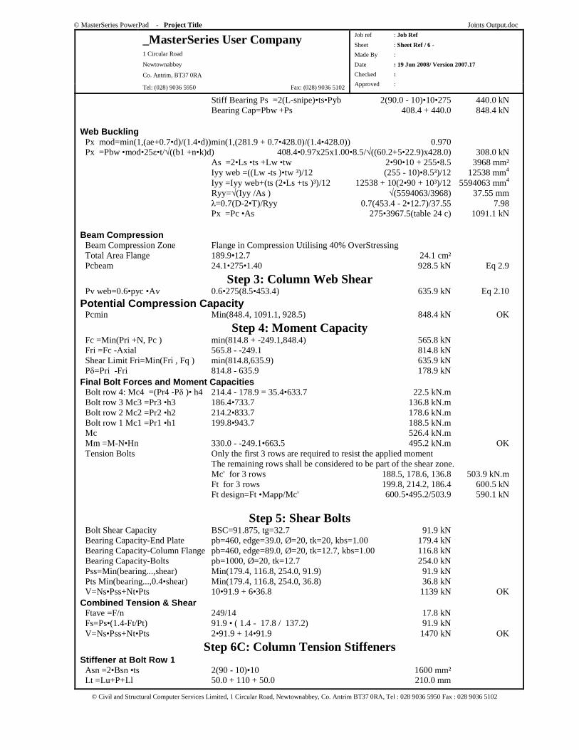
Stiff Bearing Ps =2(L-snipe)•ts•Pyb 2(90.0 - 10)•10•275 440.0 kN Bearing Cap=Pbw +Ps 408.4 + 440.0 848.4 kN Web Buckling Px mod=min(1,(ae+0.7•d)/(1.4•d)) min(1,(281.9 + 0.7•428.0)/(1.4•428.0)) 0.970 Px =Pbw •mod•25ε•t/√((b1 +n•k)d) 408.4•0.97x25x1.00•8.5/√((60.2+5•22.9)x428.0) 308.0 kN As =2•Ls •ts +Lw •tw 2•90•10 + 255•8.5 3968 mm² Iyy web =((Lw -ts )•tw ³)/12 (255 - 10)•8.5³)/12 12538 mm4
Iyy =Iyy web+(ts (2•Ls +ts )³)/12 12538 + 10(2•90 + 10³)/12 5594063 mm4
Ryy=√(Iyy /As ) √(5594063/3968) 37.55 mm λ=0.7(D-2•T)/Ryy 0.7(453.4 - 2•12.7)/37.55 7.98 Px =Pc •As 275•3967.5(table 24 c) 1091.1 kN Beam Compression Beam Compression Zone Flange in Compression Utilising 40% OverStressing Total Area Flange 189.9•12.7 24.1 cm² Pcbeam 24.1•275•1.40 928.5 kN Eq 2.9
Step 3: Column Web Shear Pv web=0.6•pyc •Av 0.6•275(8.5•453.4) 635.9 kN Eq 2.10
Potential Compression Capacity Pcmin Min(848.4, 1091.1, 928.5) 848.4 kN OK
Step 4: Moment Capacity Fc =Min(Pri +N, Pc ) min(814.8 + -249.1,848.4) 565.8 kN Fri =Fc -Axial 565.8 - -249.1 814.8 kN Shear Limit Fri=Min(Fri , Fq ) min(814.8,635.9) 635.9 kN Pδ=Pri -Fri 814.8 - 635.9 178.9 kN Final Bolt Forces and Moment Capacities Bolt row 4: Mc4 =(Pr4 -Pδ )• h4 214.4 - 178.9 = 35.4•633.7 22.5 kN.m Bolt row 3 Mc3 =Pr3 •h3 186.4•733.7 136.8 kN.m Bolt row 2 Mc2 =Pr2 •h2 214.2•833.7 178.6 kN.m Bolt row 1 Mc1 =Pr1 •h1 199.8•943.7 188.5 kN.m Mc 526.4 kN.m Mm =M-N•Hn 330.0 - -249.1•663.5 495.2 kN.m OK Tension Bolts Only the first 3 rows are required to resist the applied moment The remaining rows shall be considered to be part of the shear zone. Mc' for 3 rows 188.5, 178.6, 136.8 503.9 kN.m Ft for 3 rows 199.8, 214.2, 186.4 600.5 kN Ft design=Ft •Mapp/Mc' 600.5•495.2/503.9 590.1 kN
Step 5: Shear Bolts Bolt Shear Capacity BSC=91.875, tg=32.7 91.9 kN Bearing Capacity-End Plate pb=460, edge=39.0, Ø=20, tk=20, kbs=1.00 179.4 kN Bearing Capacity-Column Flange pb=460, edge=89.0, Ø=20, tk=12.7, kbs=1.00 116.8 kN Bearing Capacity-Bolts pb=1000, Ø=20, tk=12.7 254.0 kN Pss=Min(bearing...,shear) Min(179.4, 116.8, 254.0, 91.9) 91.9 kN Pts Min(bearing...,0.4•shear) Min(179.4, 116.8, 254.0, 36.8) 36.8 kN V=Ns•Pss+Nt•Pts 10•91.9 + 6•36.8 1139 kN OK Combined Tension & Shear Ftave =F/n 249/14 17.8 kN Fs=Ps•(1.4-Ft/Pt) 91.9 • ( 1.4 - 17.8 / 137.2) 91.9 kN V=Ns•Pss+Nt•Pts 2•91.9 + 14•91.9 1470 kN OK
Step 6C: Column Tension Stiffeners Stiffener at Bolt Row 1 Asn =2•Bsn •ts 2(90 - 10)•10 1600 mm² Lt =Lu+P+Ll 50.0 + 110 + 50.0 210.0 mm

© MasterSeries PowerPad - Project Title Joints Output.doc
_MasterSeries User Company 1 Circular Road
Newtownabbey
Co. Antrim, BT37 0RA
Tel: (028) 9036 5950 Fax: (028) 9036 5102
Job ref : Job Ref
Sheet : Sheet Ref / 7 -
Made By :
Date : 19 Jun 2008/ Version 2007.17
Checked :
Approved :
© Civil and Structural Computer Services Limited, 1 Circular Road, Newtownabbey, Co. Antrim BT37 0RA, Tel : 028 9036 5950 Fax : 028 9036 5102
Tension Asn req =(Fu +Fl )/pyt -Lt •t (199.8 + 214.2)/275 - 210.0•9 0.0 mm² OK F1 =Fu •m1 /(m1 +m2u ) 199.8•32.6/(32.6 + 46.6) 82.2 kN F2 =Fl •m1 /(m1 +m2l ) 214.2•32.6/(32.6 + 43.8) 91.4 kN Bending Asn req =(F1 +F2 )/py (82.2 + 91.4)/275 631.3 mm² OK Bending fm =3•F/2•la /(Ls •Ls •ts ) 3•173.6/2•40.8/(428•428•10) 5.8 N/mm² OK Shear fv =F/2/(Ls -snipe)/ts 173.6/2/(428 - 10)/10 20.8 N/mm² pv =0.6•py 0.6•275.0 165.0 N/mm² OK Weld Tension fs =F/2/l t /( 2•0.7•leg) 173.6/2/(90 - 10)/( 2•0.7•6) 129.2 N/mm² OK Stiffener at Bolt Row 3 Asn =2•Bsn •ts 2(90 - 10)•10 1600 mm² Lt =Lu+P+Ll 50.0 + 100 + 50.0 200.0 mm Tension Asn req =(Fu +Fl )/pyt -Lt •t (186.4 + 35.4)/275 - 200.0•9 0.0 mm² OK F1 =Fu •m1 /(m1 +m2u ) 186.4•32.6/(32.6 + 40.2) 83.5 kN F2 =Fl •m1 /(m1 +m2l ) 35.4•32.6/(32.6 + 40.2) 15.9 kN Bending Asn req =(F1 +F2 )/py (83.5 + 15.9)/275 361.2 mm² OK Bending fm =3•F/2•la /(Ls •Ls •ts ) 3•99.3/2•40.8/(165•165•10) 22.3 N/mm² OK Shear fv =F/2/(Ls -snipe)/ts 99.3/2/(165 - 10)/10 32.0 N/mm² pv =0.6•py 0.6•275.0 165.0 N/mm² OK Weld Tension fs =F/2/l t /( 2•0.7•leg) 99.3/2/(90 - 10)/( 2•0.7•6) 73.9 N/mm² OK
Step 6C: Beam Tension Stiffeners Stiffener at Bolt Row 5 Asn =2•Bsn •ts 2(90 - 10)•13 2032 mm² Lt =Lu+P+Ll 50.0 + 260 + 50.0 360.0 mm Tension Asn req =(Fu +Fl )/pyt -Lt •t (0.0 + 0.0)/275 - 360.0•9 0.0 mm² OK F1 =Fu •m1 /(m1 +m2u ) 0.0•36.0/(36.0 + 82.8) 0.0 kN F2 =Fl •m1 /(m1 +m2l ) 0.0•36.0/(36.0 + 154.9) 0.0 kN Bending Asn req =(F1 +F2 )/py (0.0 + 0.0)/275 0.0 mm² OK Bending fm =3•F/2•la /(Ls •Ls •ts ) 3•0.0/2•40.8/(165•165•13) 0.0 N/mm² OK Shear fv =F/2/(Ls -snipe)/ts 0.0/2/(165 - 10)/13 0.0 N/mm² pv =0.6•py 0.6•275.0 165.0 N/mm² OK Weld Tension fs =F/2/l t /( 2•0.7•leg) 0.0/2/(90 - 10)/( 2•0.7•6) 0.0 N/mm² OK Extended End-plate Stiffener Asn =Bsn •ts 100•10 1000 mm² Fapp =Fu •m1 /(m1 +m2 ) 199.8•43.6/(43.6 + 35.2) 110.5 kN Tension Asn req=Fapp /pyt 110.5/275 401.9 mm² OK Bending fs =3•F•la /(Ls •Ls •ts ) 3•110.5•50.0/(165•165•10) 60.9 N/mm² OK Shear fv =F/(Ls -snipe)/ts 110.5/(165 - 10)/10 71.3 N/mm² pv =0.6•py 0.6•275.0 165.0 N/mm² OK Weld Tension fs =F/lt /(2•0.7•leg) 110.5/100/(2•0.7•6) <= 275 131.6 N/mm² OK Weld Bending fmw =fm •ts /(2•0.7•leg)60.9•10/(2•0.7• 6) <= 275 72.5 N/mm² OK Weld Shear fvw =fv •ts /(2•0.7•leg) 71.3•10/(2•0.7•6) 84.9 N/mm² OK
Steps 7&8: Welds Flange Tension Weld Fapp =min(B•T•Py, Ft design) Min(189.9•12.7•275, 590.1) 590.1 kN FwCap =2•0.7•ts •L•Pyw 2•0.7•11•(189.9 - 2•8)•275 736.5 OK Flange Compression Weld Direct Bearing assumed. No check required Web Welds in Tension Zone Lwt=L-proj-T-root+1.73•g/2 260 - 100 - 12.8 - 10.2 + 1.73 90/2 214.9 mm Load per row Row1 =K1 •Fr1 0•200 0.0 kN
© MasterSeries PowerPad - Project Title Joints Output.doc
_MasterSeries User Company 1 Circular Road
Newtownabbey
Co. Antrim, BT37 0RA
Tel: (028) 9036 5950 Fax: (028) 9036 5102
Job ref : Job Ref
Sheet : Sheet Ref / 8 -
Made By :
Date : 19 Jun 2008/ Version 2007.17
Checked :
Approved :
© Civil and Structural Computer Services Limited, 1 Circular Road, Newtownabbey, Co. Antrim BT37 0RA, Tel : 028 9036 5950 Fax : 028 9036 5102
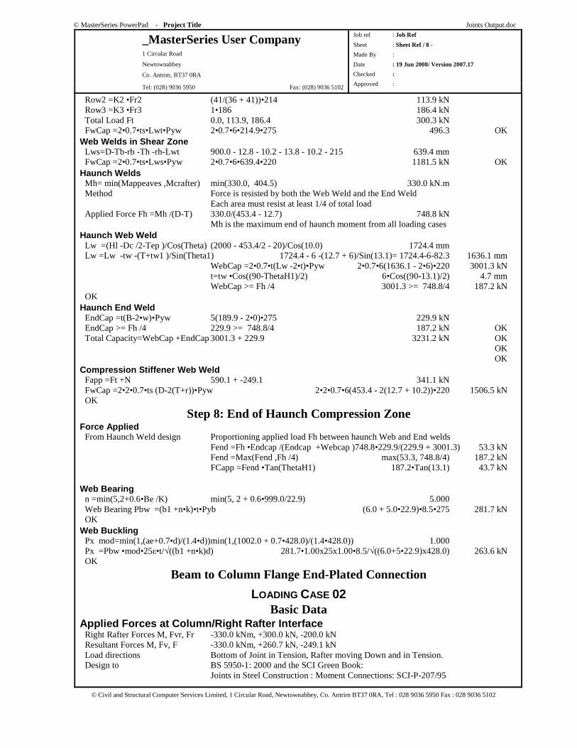
Row2 =K2 •Fr2 (41/(36 + 41))•214 113.9 kN Row3 =K3 •Fr3 1•186 186.4 kN Total Load Ft 0.0, 113.9, 186.4 300.3 kN FwCap =2•0.7•ts•Lwt•Pyw 2•0.7•6•214.9•275 496.3 OK Web Welds in Shear Zone Lws=D-Tb-rb -Th -rh-Lwt 900.0 - 12.8 - 10.2 - 13.8 - 10.2 - 215 639.4 mm FwCap =2•0.7•ts•Lws•Pyw 2•0.7•6•639.4•220 1181.5 kN OK Haunch Welds Mh= min(Mappeaves ,Mcrafter) min(330.0, 404.5) 330.0 kN.m Method Force is resisted by both the Web Weld and the End Weld Each area must resist at least 1/4 of total load Applied Force Fh =Mh /(D-T) 330.0/(453.4 - 12.7) 748.8 kN Mh is the maximum end of haunch moment from all loading cases Haunch Web Weld Lw =(Hl -Dc /2-Tep )/Cos(Τheta) (2000 - 453.4/2 - 20)/Cos(10.0) 1724.4 mm Lw =Lw -tw -(T+tw1 )/Sin(Theta1) 1724.4 - 6 -(12.7 + 6)/Sin(13.1)= 1724.4-6-82.3 1636.1 mm WebCap =2•0.7•t(Lw -2•t)•Pyw 2•0.7•6(1636.1 - 2•6)•220 3001.3 kN t=tw •Cos((90-ThetaH1)/2) 6•Cos((90-13.1)/2) 4.7 mm WebCap >= Fh /4 3001.3 >= 748.8/4 187.2 kN OK Haunch End Weld EndCap =t(B-2•w)•Pyw 5(189.9 - 2•0)•275 229.9 kN EndCap >= Fh /4 229.9 >= 748.8/4 187.2 kN OK Total Capacity=WebCap +EndCap 3001.3 + 229.9 3231.2 kN OK OK OK Compression Stiffener Web Weld Fapp =Ft +N 590.1 + -249.1 341.1 kN FwCap =2•2•0.7•ts (D-2(T+r))•Pyw 2•2•0.7•6(453.4 - 2(12.7 + 10.2))•220 1506.5 kN OK
Step 8: End of Haunch Compression Zone Force Applied From Haunch Weld design Proportioning applied load Fh between haunch Web and End welds Fend =Fh •Endcap /(Endcap +Webcap )748.8•229.9/(229.9 + 3001.3) 53.3 kN Fend =Max(Fend ,Fh /4) max(53.3, 748.8/4) 187.2 kN FCapp =Fend •Tan(ThetaH1) 187.2•Tan(13.1) 43.7 kN Web Bearing n =min(5,2+0.6•Be /K) min(5, 2 + 0.6•999.0/22.9) 5.000 Web Bearing Pbw =(b1 +n•k)•t•Pyb (6.0 + 5.0•22.9)•8.5•275 281.7 kN OK Web Buckling Px mod=min(1,(ae+0.7•d)/(1.4•d)) min(1,(1002.0 + 0.7•428.0)/(1.4•428.0)) 1.000 Px =Pbw •mod•25ε•t/√((b1 +n•k)d) 281.7•1.00x25x1.00•8.5/√((6.0+5•22.9)x428.0) 263.6 kN OK
Beam to Column Flange End-Plated Connection
LOADING CASE 02 Basic Data
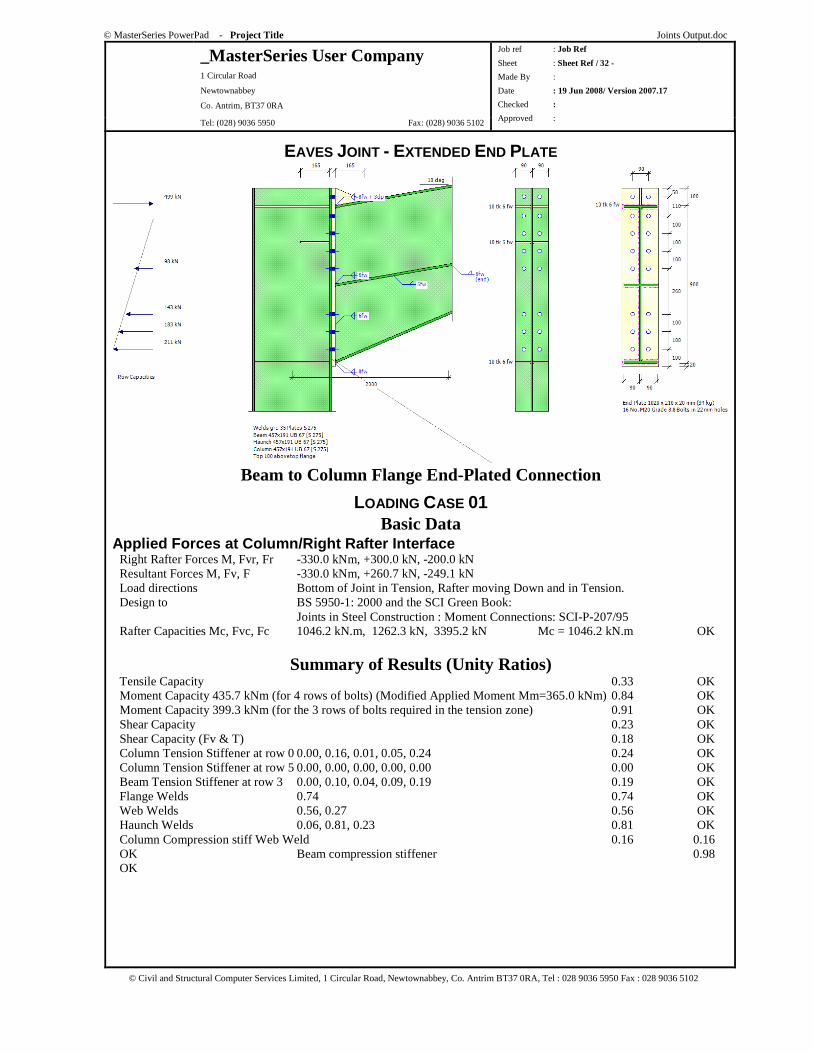
Applied Forces at Column/Right Rafter Interface Right Rafter Forces M, Fvr, Fr -330.0 kNm, +300.0 kN, -200.0 kN Resultant Forces M, Fv, F -330.0 kNm, +260.7 kN, -249.1 kN Load directions Bottom of Joint in Tension, Rafter moving Down and in Tension. Design to BS 5950-1: 2000 and the SCI Green Book: Joints in Steel Construction : Moment Connections: SCI-P-207/95
© MasterSeries PowerPad - Project Title Joints Output.doc
_MasterSeries User Company 1 Circular Road
Newtownabbey
Co. Antrim, BT37 0RA
Tel: (028) 9036 5950 Fax: (028) 9036 5102
Job ref : Job Ref
Sheet : Sheet Ref / 9 -
Made By :
Date : 19 Jun 2008/ Version 2007.17
Checked :
Approved :
© Civil and Structural Computer Services Limited, 1 Circular Road, Newtownabbey, Co. Antrim BT37 0RA, Tel : 028 9036 5950 Fax : 028 9036 5102
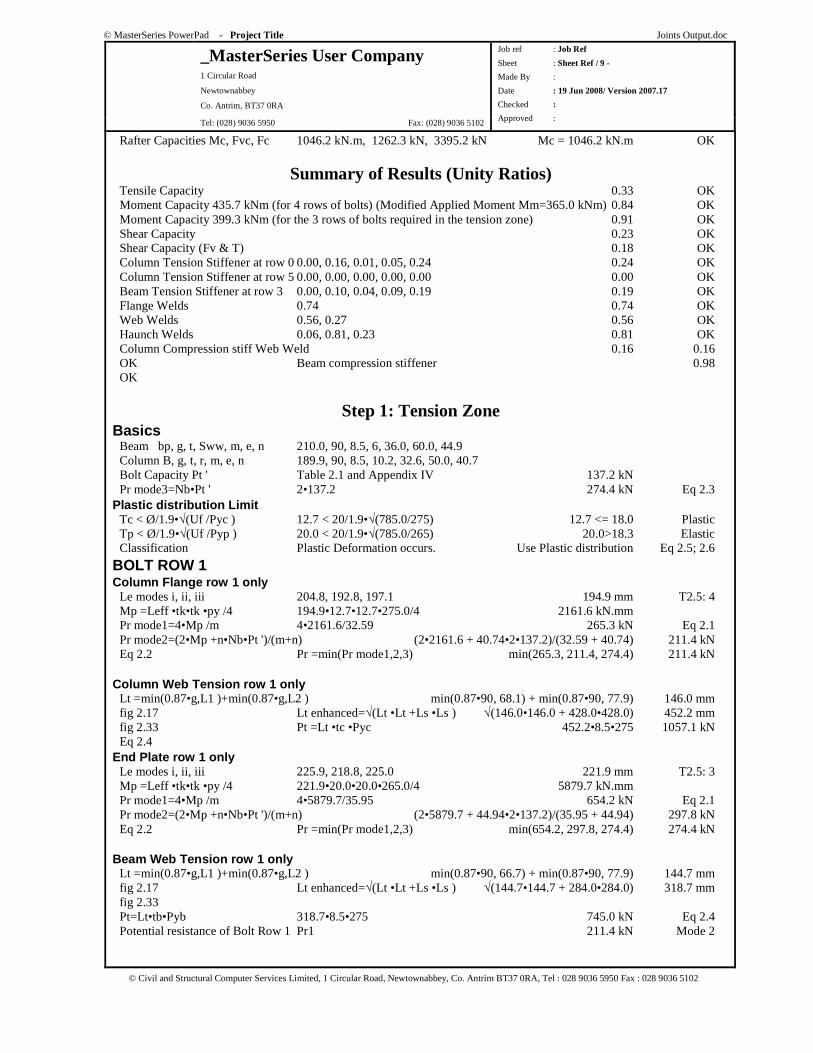
Rafter Capacities Mc, Fvc, Fc 1046.2 kN.m, 1262.3 kN, 3395.2 kN Mc = 1046.2 kN.m OK
Summary of Results (Unity Ratios) Tensile Capacity 0.33 OK Moment Capacity 435.7 kNm (for 4 rows of bolts) (Modified Applied Moment Mm=365.0 kNm) 0.84 OK Moment Capacity 399.3 kNm (for the 3 rows of bolts required in the tension zone) 0.91 OK Shear Capacity 0.23 OK Shear Capacity (Fv & T) 0.18 OK Column Tension Stiffener at row 0 0.00, 0.16, 0.01, 0.05, 0.24 0.24 OK Column Tension Stiffener at row 5 0.00, 0.00, 0.00, 0.00, 0.00 0.00 OK Beam Tension Stiffener at row 3 0.00, 0.10, 0.04, 0.09, 0.19 0.19 OK Flange Welds 0.74 0.74 OK Web Welds 0.56, 0.27 0.56 OK Haunch Welds 0.06, 0.81, 0.23 0.81 OK Column Compression stiff Web Weld 0.16 0.16 OK Beam compression stiffener 0.98 OK
Step 1: Tension Zone Basics Beam bp, g, t, Sww, m, e, n 210.0, 90, 8.5, 6, 36.0, 60.0, 44.9 Column B, g, t, r, m, e, n 189.9, 90, 8.5, 10.2, 32.6, 50.0, 40.7 Bolt Capacity Pt ' Table 2.1 and Appendix IV 137.2 kN Pr mode3=Nb•Pt ' 2•137.2 274.4 kN Eq 2.3 Plastic distribution Limit Tc < Ø/1.9•√(Uf /Pyc ) 12.7 < 20/1.9•√(785.0/275) 12.7 <= 18.0 Plastic Tp < Ø/1.9•√(Uf /Pyp ) 20.0 < 20/1.9•√(785.0/265) 20.0>18.3 Elastic Classification Plastic Deformation occurs. Use Plastic distribution Eq 2.5; 2.6
BOLT ROW 1 Column Flange row 1 only Le modes i, ii, iii 204.8, 192.8, 197.1 194.9 mm T2.5: 4 Mp =Leff •tk•tk •py /4 194.9•12.7•12.7•275.0/4 2161.6 kN.mm Pr mode1=4•Mp /m 4•2161.6/32.59 265.3 kN Eq 2.1 Pr mode2=(2•Mp +n•Nb•Pt ')/(m+n) (2•2161.6 + 40.74•2•137.2)/(32.59 + 40.74) 211.4 kN Eq 2.2 Pr =min(Pr mode1,2,3) min(265.3, 211.4, 274.4) 211.4 kN Column Web Tension row 1 only Lt =min(0.87•g,L1 )+min(0.87•g,L2 ) min(0.87•90, 68.1) + min(0.87•90, 77.9) 146.0 mm fig 2.17 Lt enhanced=√(Lt •Lt +Ls •Ls ) √(146.0•146.0 + 428.0•428.0) 452.2 mm fig 2.33 Pt =Lt •tc •Pyc 452.2•8.5•275 1057.1 kN Eq 2.4 End Plate row 1 only Le modes i, ii, iii 225.9, 218.8, 225.0 221.9 mm T2.5: 3 Mp =Leff •tk•tk •py /4 221.9•20.0•20.0•265.0/4 5879.7 kN.mm Pr mode1=4•Mp /m 4•5879.7/35.95 654.2 kN Eq 2.1 Pr mode2=(2•Mp +n•Nb•Pt ')/(m+n) (2•5879.7 + 44.94•2•137.2)/(35.95 + 44.94) 297.8 kN Eq 2.2 Pr =min(Pr mode1,2,3) min(654.2, 297.8, 274.4) 274.4 kN Beam Web Tension row 1 only Lt =min(0.87•g,L1 )+min(0.87•g,L2 ) min(0.87•90, 66.7) + min(0.87•90, 77.9) 144.7 mm fig 2.17 Lt enhanced=√(Lt •Lt +Ls •Ls ) √(144.7•144.7 + 284.0•284.0) 318.7 mm fig 2.33 Pt=Lt•tb•Pyb 318.7•8.5•275 745.0 kN Eq 2.4 Potential resistance of Bolt Row 1 Pr1 211.4 kN Mode 2
© MasterSeries PowerPad - Project Title Joints Output.doc
_MasterSeries User Company 1 Circular Road
Newtownabbey
Co. Antrim, BT37 0RA
Tel: (028) 9036 5950 Fax: (028) 9036 5102
Job ref : Job Ref
Sheet : Sheet Ref / 10 -
Made By :
Date : 19 Jun 2008/ Version 2007.17
Checked :
Approved :
© Civil and Structural Computer Services Limited, 1 Circular Road, Newtownabbey, Co. Antrim BT37 0RA, Tel : 028 9036 5950 Fax : 028 9036 5102
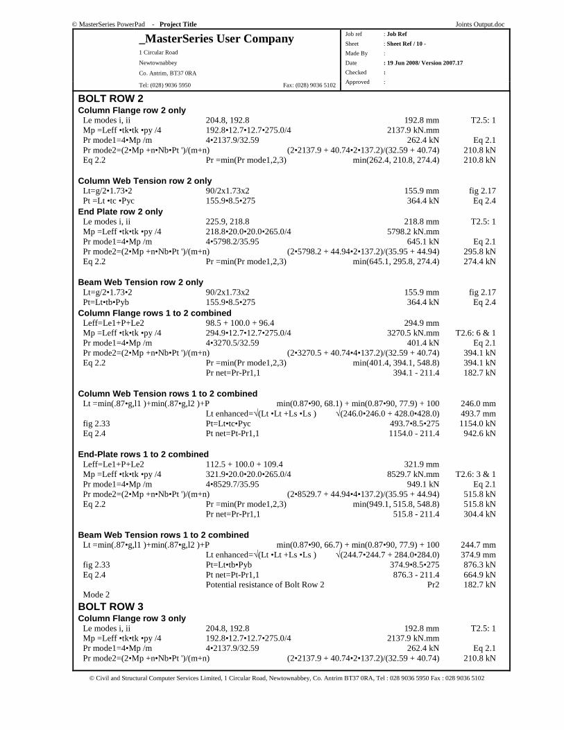
BOLT ROW 2 Column Flange row 2 only Le modes i, ii 204.8, 192.8 192.8 mm T2.5: 1 Mp =Leff •tk•tk •py /4 192.8•12.7•12.7•275.0/4 2137.9 kN.mm Pr mode1=4•Mp /m 4•2137.9/32.59 262.4 kN Eq 2.1 Pr mode2=(2•Mp +n•Nb•Pt ')/(m+n) (2•2137.9 + 40.74•2•137.2)/(32.59 + 40.74) 210.8 kN Eq 2.2 Pr =min(Pr mode1,2,3) min(262.4, 210.8, 274.4) 210.8 kN Column Web Tension row 2 only Lt=g/2•1.73•2 90/2x1.73x2 155.9 mm fig 2.17 Pt =Lt •tc •Pyc 155.9•8.5•275 364.4 kN Eq 2.4 End Plate row 2 only Le modes i, ii 225.9, 218.8 218.8 mm T2.5: 1 Mp =Leff •tk•tk •py /4 218.8•20.0•20.0•265.0/4 5798.2 kN.mm Pr mode1=4•Mp /m 4•5798.2/35.95 645.1 kN Eq 2.1 Pr mode2=(2•Mp +n•Nb•Pt ')/(m+n) (2•5798.2 + 44.94•2•137.2)/(35.95 + 44.94) 295.8 kN Eq 2.2 Pr =min(Pr mode1,2,3) min(645.1, 295.8, 274.4) 274.4 kN Beam Web Tension row 2 only Lt=g/2•1.73•2 90/2x1.73x2 155.9 mm fig 2.17 Pt=Lt•tb•Pyb 155.9•8.5•275 364.4 kN Eq 2.4 Column Flange rows 1 to 2 combined Leff=Le1+P+Le2 98.5 + 100.0 + 96.4 294.9 mm Mp =Leff •tk•tk •py /4 294.9•12.7•12.7•275.0/4 3270.5 kN.mm T2.6: 6 & 1 Pr mode1=4•Mp /m 4•3270.5/32.59 401.4 kN Eq 2.1 Pr mode2=(2•Mp +n•Nb•Pt ')/(m+n) (2•3270.5 + 40.74•4•137.2)/(32.59 + 40.74) 394.1 kN Eq 2.2 Pr =min(Pr mode1,2,3) min(401.4, 394.1, 548.8) 394.1 kN Pr net=Pr-Pr1,1 394.1 - 211.4 182.7 kN Column Web Tension rows 1 to 2 combined Lt =min(.87•g,l1 )+min(.87•g,l2 )+P min(0.87•90, 68.1) + min(0.87•90, 77.9) + 100 246.0 mm Lt enhanced=√(Lt •Lt +Ls •Ls ) √(246.0•246.0 + 428.0•428.0) 493.7 mm fig 2.33 Pt=Lt•tc•Pyc 493.7•8.5•275 1154.0 kN Eq 2.4 Pt net=Pt-Pr1,1 1154.0 - 211.4 942.6 kN End-Plate rows 1 to 2 combined Leff=Le1+P+Le2 112.5 + 100.0 + 109.4 321.9 mm Mp =Leff •tk•tk •py /4 321.9•20.0•20.0•265.0/4 8529.7 kN.mm T2.6: 3 & 1 Pr mode1=4•Mp /m 4•8529.7/35.95 949.1 kN Eq 2.1 Pr mode2=(2•Mp +n•Nb•Pt ')/(m+n) (2•8529.7 + 44.94•4•137.2)/(35.95 + 44.94) 515.8 kN Eq 2.2 Pr =min(Pr mode1,2,3) min(949.1, 515.8, 548.8) 515.8 kN Pr net=Pr-Pr1,1 515.8 - 211.4 304.4 kN Beam Web Tension rows 1 to 2 combined Lt =min(.87•g,l1 )+min(.87•g,l2 )+P min(0.87•90, 66.7) + min(0.87•90, 77.9) + 100 244.7 mm Lt enhanced=√(Lt •Lt +Ls •Ls ) √(244.7•244.7 + 284.0•284.0) 374.9 mm fig 2.33 Pt=Lt•tb•Pyb 374.9•8.5•275 876.3 kN Eq 2.4 Pt net=Pt-Pr1,1 876.3 - 211.4 664.9 kN Potential resistance of Bolt Row 2 Pr2 182.7 kN Mode 2
BOLT ROW 3 Column Flange row 3 only Le modes i, ii 204.8, 192.8 192.8 mm T2.5: 1 Mp =Leff •tk•tk •py /4 192.8•12.7•12.7•275.0/4 2137.9 kN.mm Pr mode1=4•Mp /m 4•2137.9/32.59 262.4 kN Eq 2.1 Pr mode2=(2•Mp +n•Nb•Pt ')/(m+n) (2•2137.9 + 40.74•2•137.2)/(32.59 + 40.74) 210.8 kN
© MasterSeries PowerPad - Project Title Joints Output.doc
_MasterSeries User Company 1 Circular Road
Newtownabbey
Co. Antrim, BT37 0RA
Tel: (028) 9036 5950 Fax: (028) 9036 5102
Job ref : Job Ref
Sheet : Sheet Ref / 11 -
Made By :
Date : 19 Jun 2008/ Version 2007.17
Checked :
Approved :
© Civil and Structural Computer Services Limited, 1 Circular Road, Newtownabbey, Co. Antrim BT37 0RA, Tel : 028 9036 5950 Fax : 028 9036 5102
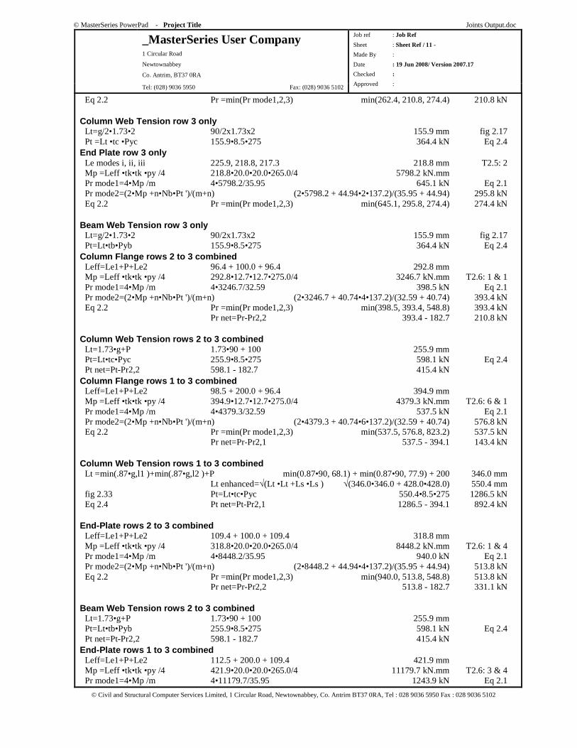
Eq 2.2 Pr =min(Pr mode1,2,3) min(262.4, 210.8, 274.4) 210.8 kN Column Web Tension row 3 only Lt=g/2•1.73•2 90/2x1.73x2 155.9 mm fig 2.17 Pt =Lt •tc •Pyc 155.9•8.5•275 364.4 kN Eq 2.4 End Plate row 3 only Le modes i, ii, iii 225.9, 218.8, 217.3 218.8 mm T2.5: 2 Mp =Leff •tk•tk •py /4 218.8•20.0•20.0•265.0/4 5798.2 kN.mm Pr mode1=4•Mp /m 4•5798.2/35.95 645.1 kN Eq 2.1 Pr mode2=(2•Mp +n•Nb•Pt ')/(m+n) (2•5798.2 + 44.94•2•137.2)/(35.95 + 44.94) 295.8 kN Eq 2.2 Pr =min(Pr mode1,2,3) min(645.1, 295.8, 274.4) 274.4 kN Beam Web Tension row 3 only Lt=g/2•1.73•2 90/2x1.73x2 155.9 mm fig 2.17 Pt=Lt•tb•Pyb 155.9•8.5•275 364.4 kN Eq 2.4 Column Flange rows 2 to 3 combined Leff=Le1+P+Le2 96.4 + 100.0 + 96.4 292.8 mm Mp =Leff •tk•tk •py /4 292.8•12.7•12.7•275.0/4 3246.7 kN.mm T2.6: 1 & 1 Pr mode1=4•Mp /m 4•3246.7/32.59 398.5 kN Eq 2.1 Pr mode2=(2•Mp +n•Nb•Pt ')/(m+n) (2•3246.7 + 40.74•4•137.2)/(32.59 + 40.74) 393.4 kN Eq 2.2 Pr =min(Pr mode1,2,3) min(398.5, 393.4, 548.8) 393.4 kN Pr net=Pr-Pr2,2 393.4 - 182.7 210.8 kN Column Web Tension rows 2 to 3 combined Lt=1.73•g+P 1.73•90 + 100 255.9 mm Pt=Lt•tc•Pyc 255.9•8.5•275 598.1 kN Eq 2.4 Pt net=Pt-Pr2,2 598.1 - 182.7 415.4 kN Column Flange rows 1 to 3 combined Leff=Le1+P+Le2 98.5 + 200.0 + 96.4 394.9 mm Mp =Leff •tk•tk •py /4 394.9•12.7•12.7•275.0/4 4379.3 kN.mm T2.6: 6 & 1 Pr mode1=4•Mp /m 4•4379.3/32.59 537.5 kN Eq 2.1 Pr mode2=(2•Mp +n•Nb•Pt ')/(m+n) (2•4379.3 + 40.74•6•137.2)/(32.59 + 40.74) 576.8 kN Eq 2.2 Pr =min(Pr mode1,2,3) min(537.5, 576.8, 823.2) 537.5 kN Pr net=Pr-Pr2,1 537.5 - 394.1 143.4 kN Column Web Tension rows 1 to 3 combined Lt =min(.87•g,l1 )+min(.87•g,l2 )+P min(0.87•90, 68.1) + min(0.87•90, 77.9) + 200 346.0 mm Lt enhanced=√(Lt •Lt +Ls •Ls ) √(346.0•346.0 + 428.0•428.0) 550.4 mm fig 2.33 Pt=Lt•tc•Pyc 550.4•8.5•275 1286.5 kN Eq 2.4 Pt net=Pt-Pr2,1 1286.5 - 394.1 892.4 kN End-Plate rows 2 to 3 combined Leff=Le1+P+Le2 109.4 + 100.0 + 109.4 318.8 mm Mp =Leff •tk•tk •py /4 318.8•20.0•20.0•265.0/4 8448.2 kN.mm T2.6: 1 & 4 Pr mode1=4•Mp /m 4•8448.2/35.95 940.0 kN Eq 2.1 Pr mode2=(2•Mp +n•Nb•Pt ')/(m+n) (2•8448.2 + 44.94•4•137.2)/(35.95 + 44.94) 513.8 kN Eq 2.2 Pr =min(Pr mode1,2,3) min(940.0, 513.8, 548.8) 513.8 kN Pr net=Pr-Pr2,2 513.8 - 182.7 331.1 kN Beam Web Tension rows 2 to 3 combined Lt=1.73•g+P 1.73•90 + 100 255.9 mm Pt=Lt•tb•Pyb 255.9•8.5•275 598.1 kN Eq 2.4 Pt net=Pt-Pr2,2 598.1 - 182.7 415.4 kN End-Plate rows 1 to 3 combined Leff=Le1+P+Le2 112.5 + 200.0 + 109.4 421.9 mm Mp =Leff •tk•tk •py /4 421.9•20.0•20.0•265.0/4 11179.7 kN.mm T2.6: 3 & 4 Pr mode1=4•Mp /m 4•11179.7/35.95 1243.9 kN Eq 2.1
© MasterSeries PowerPad - Project Title Joints Output.doc
_MasterSeries User Company 1 Circular Road
Newtownabbey
Co. Antrim, BT37 0RA
Tel: (028) 9036 5950 Fax: (028) 9036 5102
Job ref : Job Ref
Sheet : Sheet Ref / 12 -
Made By :
Date : 19 Jun 2008/ Version 2007.17
Checked :
Approved :
© Civil and Structural Computer Services Limited, 1 Circular Road, Newtownabbey, Co. Antrim BT37 0RA, Tel : 028 9036 5950 Fax : 028 9036 5102
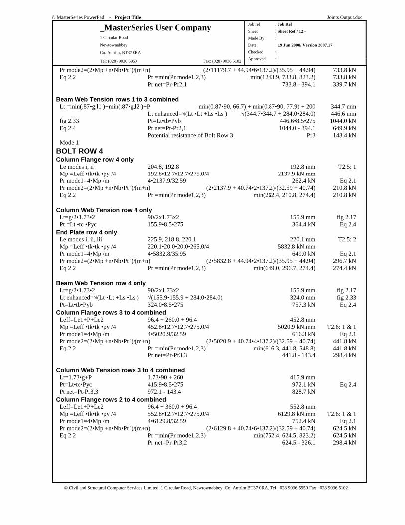
Pr mode2=(2•Mp +n•Nb•Pt ')/(m+n) (2•11179.7 + 44.94•6•137.2)/(35.95 + 44.94) 733.8 kN Eq 2.2 Pr =min(Pr mode1,2,3) min(1243.9, 733.8, 823.2) 733.8 kN Pr net=Pr-Pr2,1 733.8 - 394.1 339.7 kN Beam Web Tension rows 1 to 3 combined Lt =min(.87•g,l1 )+min(.87•g,l2 )+P min(0.87•90, 66.7) + min(0.87•90, 77.9) + 200 344.7 mm Lt enhanced=√(Lt •Lt +Ls •Ls ) √(344.7•344.7 + 284.0•284.0) 446.6 mm fig 2.33 Pt=Lt•tb•Pyb 446.6•8.5•275 1044.0 kN Eq 2.4 Pt net=Pt-Pr2,1 1044.0 - 394.1 649.9 kN Potential resistance of Bolt Row 3 Pr3 143.4 kN Mode 1
BOLT ROW 4 Column Flange row 4 only Le modes i, ii 204.8, 192.8 192.8 mm T2.5: 1 Mp =Leff •tk•tk •py /4 192.8•12.7•12.7•275.0/4 2137.9 kN.mm Pr mode1=4•Mp /m 4•2137.9/32.59 262.4 kN Eq 2.1 Pr mode2=(2•Mp +n•Nb•Pt ')/(m+n) (2•2137.9 + 40.74•2•137.2)/(32.59 + 40.74) 210.8 kN Eq 2.2 Pr =min(Pr mode1,2,3) min(262.4, 210.8, 274.4) 210.8 kN Column Web Tension row 4 only Lt=g/2•1.73•2 90/2x1.73x2 155.9 mm fig 2.17 Pt =Lt •tc •Pyc 155.9•8.5•275 364.4 kN Eq 2.4 End Plate row 4 only Le modes i, ii, iii 225.9, 218.8, 220.1 220.1 mm T2.5: 2 Mp =Leff •tk•tk •py /4 220.1•20.0•20.0•265.0/4 5832.8 kN.mm Pr mode1=4•Mp /m 4•5832.8/35.95 649.0 kN Eq 2.1 Pr mode2=(2•Mp +n•Nb•Pt ')/(m+n) (2•5832.8 + 44.94•2•137.2)/(35.95 + 44.94) 296.7 kN Eq 2.2 Pr =min(Pr mode1,2,3) min(649.0, 296.7, 274.4) 274.4 kN Beam Web Tension row 4 only Lt=g/2•1.73•2 90/2x1.73x2 155.9 mm fig 2.17 Lt enhanced=√(Lt •Lt +Ls •Ls ) √(155.9•155.9 + 284.0•284.0) 324.0 mm fig 2.33 Pt=Lt•tb•Pyb 324.0•8.5•275 757.3 kN Eq 2.4 Column Flange rows 3 to 4 combined Leff=Le1+P+Le2 96.4 + 260.0 + 96.4 452.8 mm Mp =Leff •tk•tk •py /4 452.8•12.7•12.7•275.0/4 5020.9 kN.mm T2.6: 1 & 1 Pr mode1=4•Mp /m 4•5020.9/32.59 616.3 kN Eq 2.1 Pr mode2=(2•Mp +n•Nb•Pt ')/(m+n) (2•5020.9 + 40.74•4•137.2)/(32.59 + 40.74) 441.8 kN Eq 2.2 Pr =min(Pr mode1,2,3) min(616.3, 441.8, 548.8) 441.8 kN Pr net=Pr-Pr3,3 441.8 - 143.4 298.4 kN Column Web Tension rows 3 to 4 combined Lt=1.73•g+P 1.73•90 + 260 415.9 mm Pt=Lt•tc•Pyc 415.9•8.5•275 972.1 kN Eq 2.4 Pt net=Pt-Pr3,3 972.1 - 143.4 828.7 kN Column Flange rows 2 to 4 combined Leff=Le1+P+Le2 96.4 + 360.0 + 96.4 552.8 mm Mp =Leff •tk•tk •py /4 552.8•12.7•12.7•275.0/4 6129.8 kN.mm T2.6: 1 & 1 Pr mode1=4•Mp /m 4•6129.8/32.59 752.4 kN Eq 2.1 Pr mode2=(2•Mp +n•Nb•Pt ')/(m+n) (2•6129.8 + 40.74•6•137.2)/(32.59 + 40.74) 624.5 kN Eq 2.2 Pr =min(Pr mode1,2,3) min(752.4, 624.5, 823.2) 624.5 kN Pr net=Pr-Pr3,2 624.5 - 326.1 298.4 kN
© MasterSeries PowerPad - Project Title Joints Output.doc
_MasterSeries User Company 1 Circular Road
Newtownabbey
Co. Antrim, BT37 0RA
Tel: (028) 9036 5950 Fax: (028) 9036 5102
Job ref : Job Ref
Sheet : Sheet Ref / 13 -
Made By :
Date : 19 Jun 2008/ Version 2007.17
Checked :
Approved :
© Civil and Structural Computer Services Limited, 1 Circular Road, Newtownabbey, Co. Antrim BT37 0RA, Tel : 028 9036 5950 Fax : 028 9036 5102
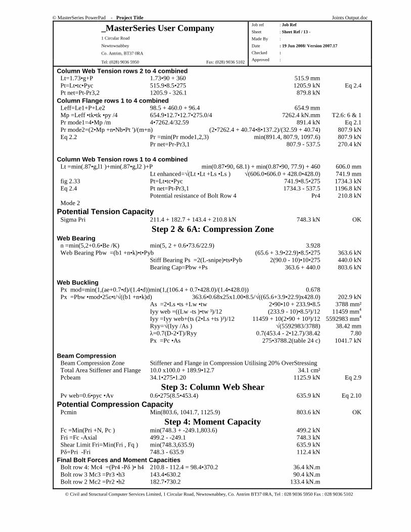
Column Web Tension rows 2 to 4 combined Lt=1.73•g+P 1.73•90 + 360 515.9 mm Pt=Lt•tc•Pyc 515.9•8.5•275 1205.9 kN Eq 2.4 Pt net=Pt-Pr3,2 1205.9 - 326.1 879.8 kN Column Flange rows 1 to 4 combined Leff=Le1+P+Le2 98.5 + 460.0 + 96.4 654.9 mm Mp =Leff •tk•tk •py /4 654.9•12.7•12.7•275.0/4 7262.4 kN.mm T2.6: 6 & 1 Pr mode1=4•Mp /m 4•7262.4/32.59 891.4 kN Eq 2.1 Pr mode2=(2•Mp +n•Nb•Pt ')/(m+n) (2•7262.4 + 40.74•8•137.2)/(32.59 + 40.74) 807.9 kN Eq 2.2 Pr =min(Pr mode1,2,3) min(891.4, 807.9, 1097.6) 807.9 kN Pr net=Pr-Pr3,1 807.9 - 537.5 270.4 kN Column Web Tension rows 1 to 4 combined Lt =min(.87•g,l1 )+min(.87•g,l2 )+P min(0.87•90, 68.1) + min(0.87•90, 77.9) + 460 606.0 mm Lt enhanced=√(Lt •Lt +Ls •Ls ) √(606.0•606.0 + 428.0•428.0) 741.9 mm fig 2.33 Pt=Lt•tc•Pyc 741.9•8.5•275 1734.3 kN Eq 2.4 Pt net=Pt-Pr3,1 1734.3 - 537.5 1196.8 kN Potential resistance of Bolt Row 4 Pr4 210.8 kN Mode 2
Potential Tension Capacity Sigma Pri 211.4 + 182.7 + 143.4 + 210.8 kN 748.3 kN OK
Step 2 & 6A: Compression Zone Web Bearing n =min(5,2+0.6•Be /K) min(5, 2 + 0.6•73.6/22.9) 3.928 Web Bearing Pbw =(b1 +n•k)•t•Pyb (65.6 + 3.9•22.9)•8.5•275 363.6 kN Stiff Bearing Ps =2(L-snipe)•ts•Pyb 2(90.0 - 10)•10•275 440.0 kN Bearing Cap=Pbw +Ps 363.6 + 440.0 803.6 kN Web Buckling Px mod=min(1,(ae+0.7•d)/(1.4•d)) min(1,(106.4 + 0.7•428.0)/(1.4•428.0)) 0.678 Px =Pbw •mod•25ε•t/√((b1 +n•k)d) 363.6•0.68x25x1.00•8.5/√((65.6+3.9•22.9)x428.0) 202.9 kN As =2•Ls •ts +Lw •tw 2•90•10 + 233.9•8.5 3788 mm² Iyy web =((Lw -ts )•tw ³)/12 (233.9 - 10)•8.5³)/12 11459 mm4
Iyy =Iyy web+(ts (2•Ls +ts )³)/12 11459 + 10(2•90 + 10³)/12 5592983 mm4
Ryy=√(Iyy /As ) √(5592983/3788) 38.42 mm λ=0.7(D-2•T)/Ryy 0.7(453.4 - 2•12.7)/38.42 7.80 Px =Pc •As 275•3788.2(table 24 c) 1041.7 kN Beam Compression Beam Compression Zone Stiffener and Flange in Compression Utilising 20% OverStressing Total Area Stiffener and Flange 10.0 x100.0 + 189.9•12.7 34.1 cm² Pcbeam 34.1•275•1.20 1125.9 kN Eq 2.9
Step 3: Column Web Shear Pv web=0.6•pyc •Av 0.6•275(8.5•453.4) 635.9 kN Eq 2.10
Potential Compression Capacity Pcmin Min(803.6, 1041.7, 1125.9) 803.6 kN OK
Step 4: Moment Capacity Fc =Min(Pri +N, Pc ) min(748.3 + -249.1,803.6) 499.2 kN Fri =Fc -Axial 499.2 - -249.1 748.3 kN Shear Limit Fri=Min(Fri , Fq ) min(748.3,635.9) 635.9 kN Pδ=Pri -Fri 748.3 - 635.9 112.4 kN Final Bolt Forces and Moment Capacities Bolt row 4: Mc4 =(Pr4 -Pδ )• h4 210.8 - 112.4 = 98.4•370.2 36.4 kN.m Bolt row 3 Mc3 =Pr3 •h3 143.4•630.2 90.4 kN.m Bolt row 2 Mc2 =Pr2 •h2 182.7•730.2 133.4 kN.m
© MasterSeries PowerPad - Project Title Joints Output.doc
_MasterSeries User Company 1 Circular Road
Newtownabbey
Co. Antrim, BT37 0RA
Tel: (028) 9036 5950 Fax: (028) 9036 5102
Job ref : Job Ref
Sheet : Sheet Ref / 14 -
Made By :
Date : 19 Jun 2008/ Version 2007.17
Checked :
Approved :
© Civil and Structural Computer Services Limited, 1 Circular Road, Newtownabbey, Co. Antrim BT37 0RA, Tel : 028 9036 5950 Fax : 028 9036 5102
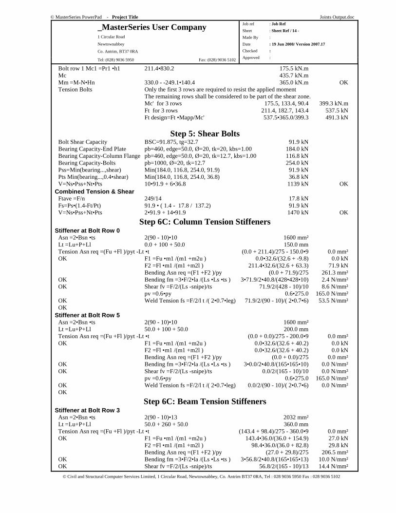
Bolt row 1 Mc1 =Pr1 •h1 211.4•830.2 175.5 kN.m Mc 435.7 kN.m Mm =M-N•Hn 330.0 - -249.1•140.4 365.0 kN.m OK Tension Bolts Only the first 3 rows are required to resist the applied moment The remaining rows shall be considered to be part of the shear zone. Mc' for 3 rows 175.5, 133.4, 90.4 399.3 kN.m Ft for 3 rows 211.4, 182.7, 143.4 537.5 kN Ft design=Ft •Mapp/Mc' 537.5•365.0/399.3 491.3 kN
Step 5: Shear Bolts Bolt Shear Capacity BSC=91.875, tg=32.7 91.9 kN Bearing Capacity-End Plate pb=460, edge=50.0, Ø=20, tk=20, kbs=1.00 184.0 kN Bearing Capacity-Column Flange pb=460, edge=50.0, Ø=20, tk=12.7, kbs=1.00 116.8 kN Bearing Capacity-Bolts pb=1000, Ø=20, tk=12.7 254.0 kN Pss=Min(bearing...,shear) Min(184.0, 116.8, 254.0, 91.9) 91.9 kN Pts Min(bearing...,0.4•shear) Min(184.0, 116.8, 254.0, 36.8) 36.8 kN V=Ns•Pss+Nt•Pts 10•91.9 + 6•36.8 1139 kN OK Combined Tension & Shear Ftave =F/n 249/14 17.8 kN Fs=Ps•(1.4-Ft/Pt) 91.9 • ( 1.4 - 17.8 / 137.2) 91.9 kN V=Ns•Pss+Nt•Pts 2•91.9 + 14•91.9 1470 kN OK
Step 6C: Column Tension Stiffeners Stiffener at Bolt Row 0 Asn =2•Bsn •ts 2(90 - 10)•10 1600 mm² Lt =Lu+P+Ll 0.0 + 100 + 50.0 150.0 mm Tension Asn req =(Fu +Fl )/pyt -Lt •t (0.0 + 211.4)/275 - 150.0•9 0.0 mm² OK F1 =Fu •m1 /(m1 +m2u ) 0.0•32.6/(32.6 + -9.8) 0.0 kN F2 =Fl •m1 /(m1 +m2l ) 211.4•32.6/(32.6 + 63.3) 71.9 kN Bending Asn req =(F1 +F2 )/py (0.0 + 71.9)/275 261.3 mm² OK Bending fm =3•F/2•la /(Ls •Ls •ts ) 3•71.9/2•40.8/(428•428•10) 2.4 N/mm² OK Shear fv =F/2/(Ls -snipe)/ts 71.9/2/(428 - 10)/10 8.6 N/mm² pv =0.6•py 0.6•275.0 165.0 N/mm² OK Weld Tension fs =F/2/l t /( 2•0.7•leg) 71.9/2/(90 - 10)/( 2•0.7•6) 53.5 N/mm² OK Stiffener at Bolt Row 5 Asn =2•Bsn •ts 2(90 - 10)•10 1600 mm² Lt =Lu+P+Ll 50.0 + 100 + 50.0 200.0 mm Tension Asn req =(Fu +Fl )/pyt -Lt •t (0.0 + 0.0)/275 - 200.0•9 0.0 mm² OK F1 =Fu •m1 /(m1 +m2u ) 0.0•32.6/(32.6 + 40.2) 0.0 kN F2 =Fl •m1 /(m1 +m2l ) 0.0•32.6/(32.6 + 40.2) 0.0 kN Bending Asn req =(F1 +F2 )/py (0.0 + 0.0)/275 0.0 mm² OK Bending fm =3•F/2•la /(Ls •Ls •ts ) 3•0.0/2•40.8/(165•165•10) 0.0 N/mm² OK Shear fv =F/2/(Ls -snipe)/ts 0.0/2/(165 - 10)/10 0.0 N/mm² pv =0.6•py 0.6•275.0 165.0 N/mm² OK Weld Tension fs =F/2/l t /( 2•0.7•leg) 0.0/2/(90 - 10)/( 2•0.7•6) 0.0 N/mm² OK
Step 6C: Beam Tension Stiffeners Stiffener at Bolt Row 3 Asn =2•Bsn •ts 2(90 - 10)•13 2032 mm² Lt =Lu+P+Ll 50.0 + 260 + 50.0 360.0 mm Tension Asn req =(Fu +Fl )/pyt -Lt •t (143.4 + 98.4)/275 - 360.0•9 0.0 mm² OK F1 =Fu •m1 /(m1 +m2u ) 143.4•36.0/(36.0 + 154.9) 27.0 kN F2 =Fl •m1 /(m1 +m2l ) 98.4•36.0/(36.0 + 82.8) 29.8 kN Bending Asn req =(F1 +F2 )/py (27.0 + 29.8)/275 206.5 mm² OK Bending fm =3•F/2•la /(Ls •Ls •ts ) 3•56.8/2•40.8/(165•165•13) 10.0 N/mm² OK Shear fv =F/2/(Ls -snipe)/ts 56.8/2/(165 - 10)/13 14.4 N/mm²
© MasterSeries PowerPad - Project Title Joints Output.doc
_MasterSeries User Company 1 Circular Road
Newtownabbey
Co. Antrim, BT37 0RA
Tel: (028) 9036 5950 Fax: (028) 9036 5102
Job ref : Job Ref
Sheet : Sheet Ref / 15 -
Made By :
Date : 19 Jun 2008/ Version 2007.17
Checked :
Approved :
© Civil and Structural Computer Services Limited, 1 Circular Road, Newtownabbey, Co. Antrim BT37 0RA, Tel : 028 9036 5950 Fax : 028 9036 5102
pv =0.6•py 0.6•275.0 165.0 N/mm² OK Weld Tension fs =F/2/l t /( 2•0.7•leg) 56.8/2/(90 - 10)/( 2•0.7•6) 42.3 N/mm² OK
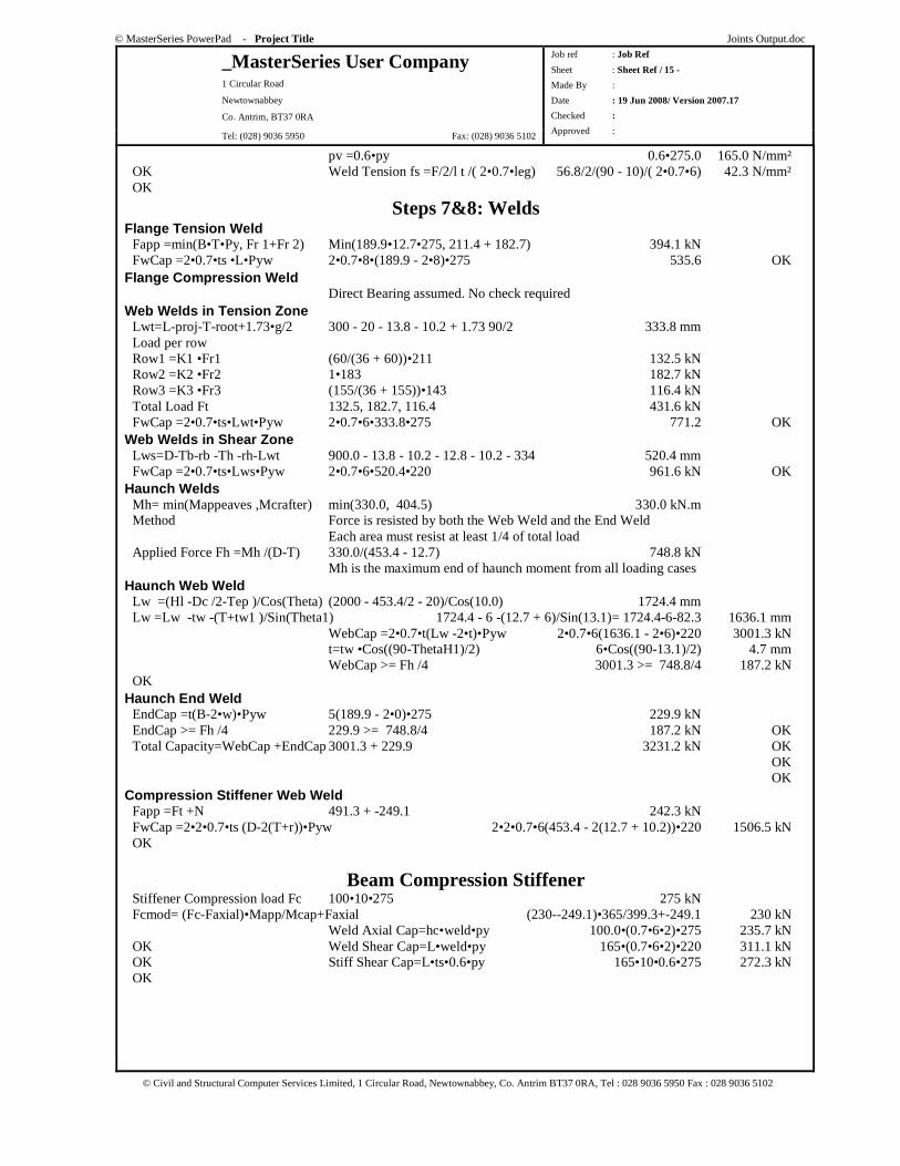
Steps 7&8: Welds Flange Tension Weld Fapp =min(B•T•Py, Fr 1+Fr 2) Min(189.9•12.7•275, 211.4 + 182.7) 394.1 kN FwCap =2•0.7•ts •L•Pyw 2•0.7•8•(189.9 - 2•8)•275 535.6 OK Flange Compression Weld Direct Bearing assumed. No check required Web Welds in Tension Zone Lwt=L-proj-T-root+1.73•g/2 300 - 20 - 13.8 - 10.2 + 1.73 90/2 333.8 mm Load per row Row1 =K1 •Fr1 (60/(36 + 60))•211 132.5 kN Row2 =K2 •Fr2 1•183 182.7 kN Row3 =K3 •Fr3 (155/(36 + 155))•143 116.4 kN Total Load Ft 132.5, 182.7, 116.4 431.6 kN FwCap =2•0.7•ts•Lwt•Pyw 2•0.7•6•333.8•275 771.2 OK Web Welds in Shear Zone Lws=D-Tb-rb -Th -rh-Lwt 900.0 - 13.8 - 10.2 - 12.8 - 10.2 - 334 520.4 mm FwCap =2•0.7•ts•Lws•Pyw 2•0.7•6•520.4•220 961.6 kN OK Haunch Welds Mh= min(Mappeaves ,Mcrafter) min(330.0, 404.5) 330.0 kN.m Method Force is resisted by both the Web Weld and the End Weld Each area must resist at least 1/4 of total load Applied Force Fh =Mh /(D-T) 330.0/(453.4 - 12.7) 748.8 kN Mh is the maximum end of haunch moment from all loading cases Haunch Web Weld Lw =(Hl -Dc /2-Tep )/Cos(Τheta) (2000 - 453.4/2 - 20)/Cos(10.0) 1724.4 mm Lw =Lw -tw -(T+tw1 )/Sin(Theta1) 1724.4 - 6 -(12.7 + 6)/Sin(13.1)= 1724.4-6-82.3 1636.1 mm WebCap =2•0.7•t(Lw -2•t)•Pyw 2•0.7•6(1636.1 - 2•6)•220 3001.3 kN t=tw •Cos((90-ThetaH1)/2) 6•Cos((90-13.1)/2) 4.7 mm WebCap >= Fh /4 3001.3 >= 748.8/4 187.2 kN OK Haunch End Weld EndCap =t(B-2•w)•Pyw 5(189.9 - 2•0)•275 229.9 kN EndCap >= Fh /4 229.9 >= 748.8/4 187.2 kN OK Total Capacity=WebCap +EndCap 3001.3 + 229.9 3231.2 kN OK OK OK Compression Stiffener Web Weld Fapp =Ft +N 491.3 + -249.1 242.3 kN FwCap =2•2•0.7•ts (D-2(T+r))•Pyw 2•2•0.7•6(453.4 - 2(12.7 + 10.2))•220 1506.5 kN OK
Beam Compression Stiffener Stiffener Compression load Fc 100•10•275 275 kN Fcmod= (Fc-Faxial)•Mapp/Mcap+Faxial (230--249.1)•365/399.3+-249.1 230 kN Weld Axial Cap=hc•weld•py 100.0•(0.7•6•2)•275 235.7 kN OK Weld Shear Cap=L•weld•py 165•(0.7•6•2)•220 311.1 kN OK Stiff Shear Cap=L•ts•0.6•py 165•10•0.6•275 272.3 kN OK
© MasterSeries PowerPad - Project Title Joints Output.doc
_MasterSeries User Company 1 Circular Road
Newtownabbey
Co. Antrim, BT37 0RA
Tel: (028) 9036 5950 Fax: (028) 9036 5102
Job ref : Job Ref
Sheet : Sheet Ref / 16 -
Made By :
Date : 19 Jun 2008/ Version 2007.17
Checked :
Approved :
© Civil and Structural Computer Services Limited, 1 Circular Road, Newtownabbey, Co. Antrim BT37 0RA, Tel : 028 9036 5950 Fax : 028 9036 5102
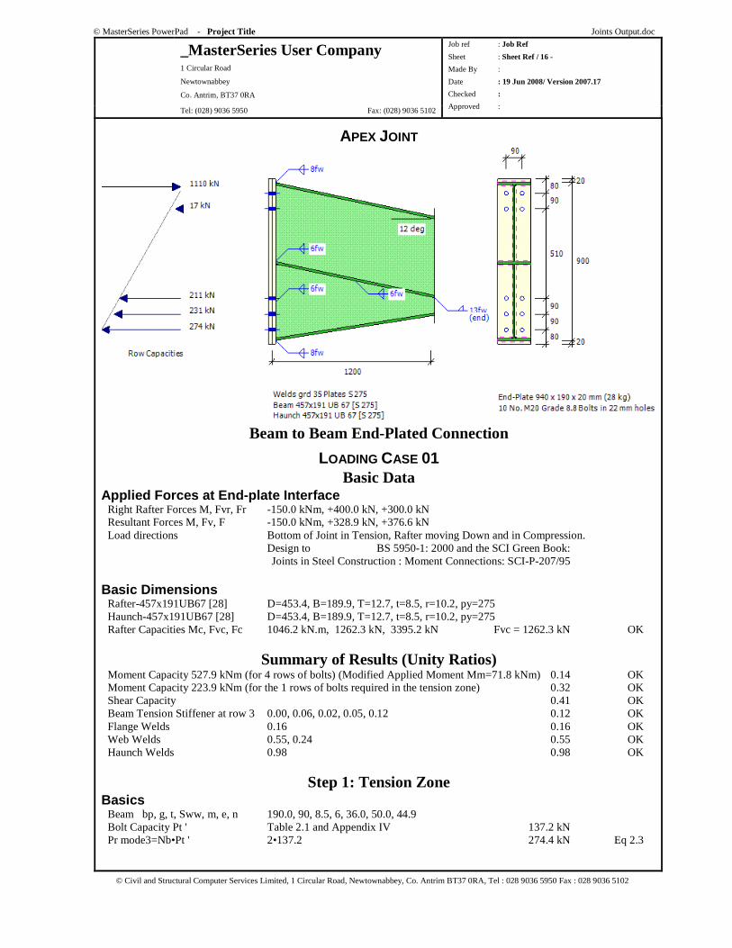
APEX JOINT
Beam to Beam End-Plated Connection
LOADING CASE 01 Basic Data
Applied Forces at End-plate Interface Right Rafter Forces M, Fvr, Fr -150.0 kNm, +400.0 kN, +300.0 kN Resultant Forces M, Fv, F -150.0 kNm, +328.9 kN, +376.6 kN Load directions Bottom of Joint in Tension, Rafter moving Down and in Compression. Design to BS 5950-1: 2000 and the SCI Green Book: Joints in Steel Construction : Moment Connections: SCI-P-207/95
Basic Dimensions Rafter-457x191UB67 [28] D=453.4, B=189.9, T=12.7, t=8.5, r=10.2, py=275 Haunch-457x191UB67 [28] D=453.4, B=189.9, T=12.7, t=8.5, r=10.2, py=275 Rafter Capacities Mc, Fvc, Fc 1046.2 kN.m, 1262.3 kN, 3395.2 kN Fvc = 1262.3 kN OK
Summary of Results (Unity Ratios) Moment Capacity 527.9 kNm (for 4 rows of bolts) (Modified Applied Moment Mm=71.8 kNm) 0.14 OK Moment Capacity 223.9 kNm (for the 1 rows of bolts required in the tension zone) 0.32 OK Shear Capacity 0.41 OK Beam Tension Stiffener at row 3 0.00, 0.06, 0.02, 0.05, 0.12 0.12 OK Flange Welds 0.16 0.16 OK Web Welds 0.55, 0.24 0.55 OK Haunch Welds 0.98 0.98 OK
Step 1: Tension Zone Basics Beam bp, g, t, Sww, m, e, n 190.0, 90, 8.5, 6, 36.0, 50.0, 44.9 Bolt Capacity Pt ' Table 2.1 and Appendix IV 137.2 kN Pr mode3=Nb•Pt ' 2•137.2 274.4 kN Eq 2.3
© MasterSeries PowerPad - Project Title Joints Output.doc
_MasterSeries User Company 1 Circular Road
Newtownabbey
Co. Antrim, BT37 0RA
Tel: (028) 9036 5950 Fax: (028) 9036 5102
Job ref : Job Ref
Sheet : Sheet Ref / 17 -
Made By :
Date : 19 Jun 2008/ Version 2007.17
Checked :
Approved :
© Civil and Structural Computer Services Limited, 1 Circular Road, Newtownabbey, Co. Antrim BT37 0RA, Tel : 028 9036 5950 Fax : 028 9036 5102
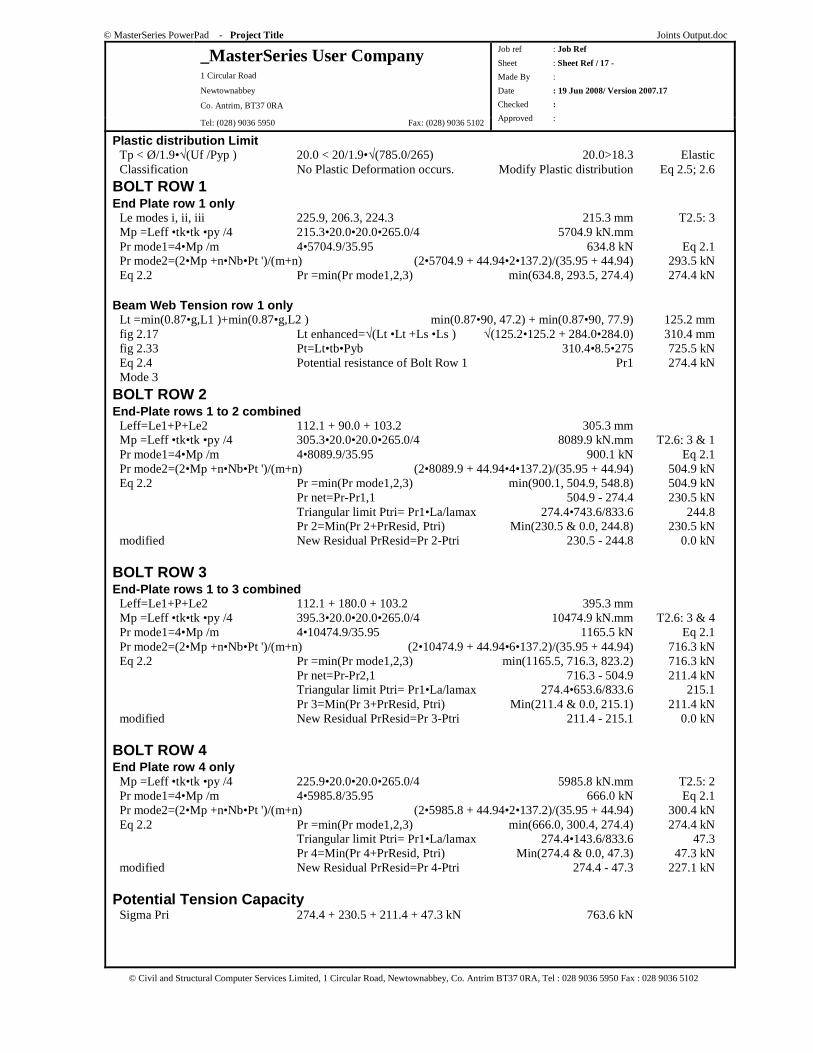
Plastic distribution Limit Tp < Ø/1.9•√(Uf /Pyp ) 20.0 < 20/1.9•√(785.0/265) 20.0>18.3 Elastic Classification No Plastic Deformation occurs. Modify Plastic distribution Eq 2.5; 2.6
BOLT ROW 1 End Plate row 1 only Le modes i, ii, iii 225.9, 206.3, 224.3 215.3 mm T2.5: 3 Mp =Leff •tk•tk •py /4 215.3•20.0•20.0•265.0/4 5704.9 kN.mm Pr mode1=4•Mp /m 4•5704.9/35.95 634.8 kN Eq 2.1 Pr mode2=(2•Mp +n•Nb•Pt ')/(m+n) (2•5704.9 + 44.94•2•137.2)/(35.95 + 44.94) 293.5 kN Eq 2.2 Pr =min(Pr mode1,2,3) min(634.8, 293.5, 274.4) 274.4 kN Beam Web Tension row 1 only Lt =min(0.87•g,L1 )+min(0.87•g,L2 ) min(0.87•90, 47.2) + min(0.87•90, 77.9) 125.2 mm fig 2.17 Lt enhanced=√(Lt •Lt +Ls •Ls ) √(125.2•125.2 + 284.0•284.0) 310.4 mm fig 2.33 Pt=Lt•tb•Pyb 310.4•8.5•275 725.5 kN Eq 2.4 Potential resistance of Bolt Row 1 Pr1 274.4 kN Mode 3
BOLT ROW 2 End-Plate rows 1 to 2 combined Leff=Le1+P+Le2 112.1 + 90.0 + 103.2 305.3 mm Mp =Leff •tk•tk •py /4 305.3•20.0•20.0•265.0/4 8089.9 kN.mm T2.6: 3 & 1 Pr mode1=4•Mp /m 4•8089.9/35.95 900.1 kN Eq 2.1 Pr mode2=(2•Mp +n•Nb•Pt ')/(m+n) (2•8089.9 + 44.94•4•137.2)/(35.95 + 44.94) 504.9 kN Eq 2.2 Pr =min(Pr mode1,2,3) min(900.1, 504.9, 548.8) 504.9 kN Pr net=Pr-Pr1,1 504.9 - 274.4 230.5 kN Triangular limit Ptri= Pr1•La/lamax 274.4•743.6/833.6 244.8 Pr 2=Min(Pr 2+PrResid, Ptri) Min(230.5 & 0.0, 244.8) 230.5 kN modified New Residual PrResid=Pr 2-Ptri 230.5 - 244.8 0.0 kN
BOLT ROW 3 End-Plate rows 1 to 3 combined Leff=Le1+P+Le2 112.1 + 180.0 + 103.2 395.3 mm Mp =Leff •tk•tk •py /4 395.3•20.0•20.0•265.0/4 10474.9 kN.mm T2.6: 3 & 4 Pr mode1=4•Mp /m 4•10474.9/35.95 1165.5 kN Eq 2.1 Pr mode2=(2•Mp +n•Nb•Pt ')/(m+n) (2•10474.9 + 44.94•6•137.2)/(35.95 + 44.94) 716.3 kN Eq 2.2 Pr =min(Pr mode1,2,3) min(1165.5, 716.3, 823.2) 716.3 kN Pr net=Pr-Pr2,1 716.3 - 504.9 211.4 kN Triangular limit Ptri= Pr1•La/lamax 274.4•653.6/833.6 215.1 Pr 3=Min(Pr 3+PrResid, Ptri) Min(211.4 & 0.0, 215.1) 211.4 kN modified New Residual PrResid=Pr 3-Ptri 211.4 - 215.1 0.0 kN
BOLT ROW 4 End Plate row 4 only Mp =Leff •tk•tk •py /4 225.9•20.0•20.0•265.0/4 5985.8 kN.mm T2.5: 2 Pr mode1=4•Mp /m 4•5985.8/35.95 666.0 kN Eq 2.1 Pr mode2=(2•Mp +n•Nb•Pt ')/(m+n) (2•5985.8 + 44.94•2•137.2)/(35.95 + 44.94) 300.4 kN Eq 2.2 Pr =min(Pr mode1,2,3) min(666.0, 300.4, 274.4) 274.4 kN Triangular limit Ptri= Pr1•La/lamax 274.4•143.6/833.6 47.3 Pr 4=Min(Pr 4+PrResid, Ptri) Min(274.4 & 0.0, 47.3) 47.3 kN modified New Residual PrResid=Pr 4-Ptri 274.4 - 47.3 227.1 kN
Potential Tension Capacity Sigma Pri 274.4 + 230.5 + 211.4 + 47.3 kN 763.6 kN
© MasterSeries PowerPad - Project Title Joints Output.doc
_MasterSeries User Company 1 Circular Road
Newtownabbey
Co. Antrim, BT37 0RA
Tel: (028) 9036 5950 Fax: (028) 9036 5102
Job ref : Job Ref
Sheet : Sheet Ref / 18 -
Made By :
Date : 19 Jun 2008/ Version 2007.17
Checked :
Approved :
© Civil and Structural Computer Services Limited, 1 Circular Road, Newtownabbey, Co. Antrim BT37 0RA, Tel : 028 9036 5950 Fax : 028 9036 5102
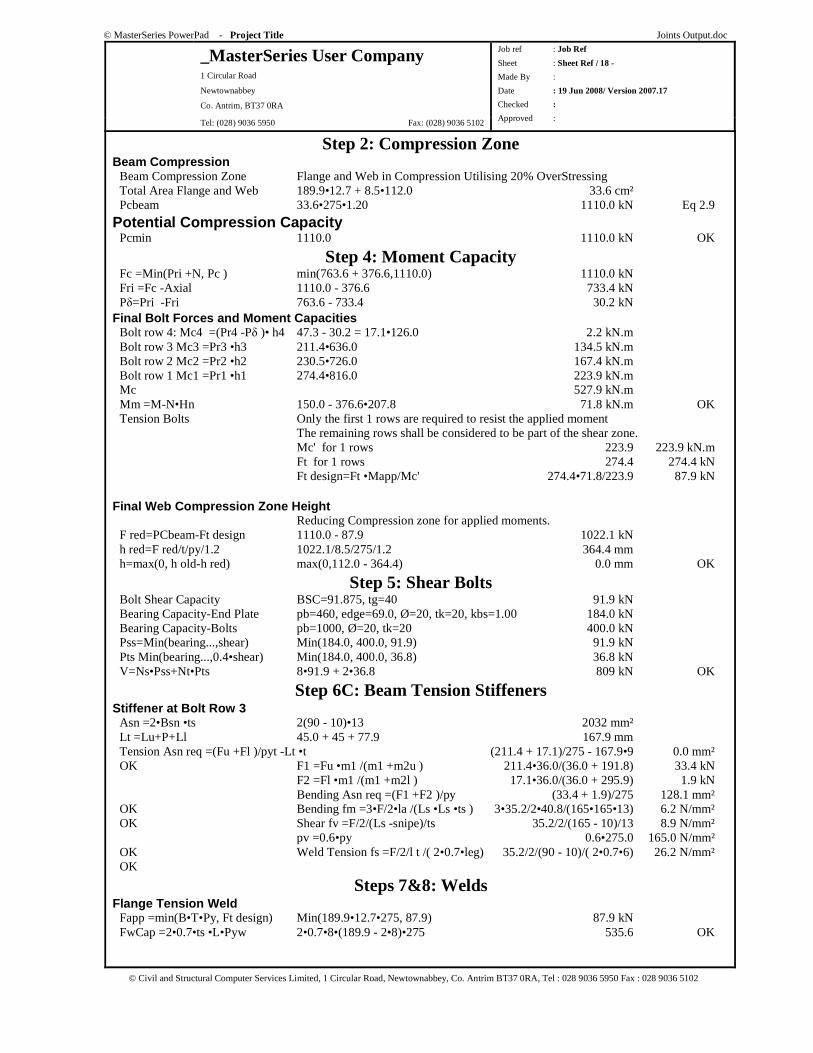
Step 2: Compression Zone Beam Compression Beam Compression Zone Flange and Web in Compression Utilising 20% OverStressing Total Area Flange and Web 189.9•12.7 + 8.5•112.0 33.6 cm² Pcbeam 33.6•275•1.20 1110.0 kN Eq 2.9
Potential Compression Capacity Pcmin 1110.0 1110.0 kN OK
Step 4: Moment Capacity Fc =Min(Pri +N, Pc ) min(763.6 + 376.6,1110.0) 1110.0 kN Fri =Fc -Axial 1110.0 - 376.6 733.4 kN Pδ=Pri -Fri 763.6 - 733.4 30.2 kN Final Bolt Forces and Moment Capacities Bolt row 4: Mc4 =(Pr4 -Pδ )• h4 47.3 - 30.2 = 17.1•126.0 2.2 kN.m Bolt row 3 Mc3 =Pr3 •h3 211.4•636.0 134.5 kN.m Bolt row 2 Mc2 =Pr2 •h2 230.5•726.0 167.4 kN.m Bolt row 1 Mc1 =Pr1 •h1 274.4•816.0 223.9 kN.m Mc 527.9 kN.m Mm =M-N•Hn 150.0 - 376.6•207.8 71.8 kN.m OK Tension Bolts Only the first 1 rows are required to resist the applied moment The remaining rows shall be considered to be part of the shear zone. Mc' for 1 rows 223.9 223.9 kN.m Ft for 1 rows 274.4 274.4 kN Ft design=Ft •Mapp/Mc' 274.4•71.8/223.9 87.9 kN Final Web Compression Zone Height Reducing Compression zone for applied moments. F red=PCbeam-Ft design 1110.0 - 87.9 1022.1 kN h red=F red/t/py/1.2 1022.1/8.5/275/1.2 364.4 mm h=max(0, h old-h red) max(0,112.0 - 364.4) 0.0 mm OK
Step 5: Shear Bolts Bolt Shear Capacity BSC=91.875, tg=40 91.9 kN Bearing Capacity-End Plate pb=460, edge=69.0, Ø=20, tk=20, kbs=1.00 184.0 kN Bearing Capacity-Bolts pb=1000, Ø=20, tk=20 400.0 kN Pss=Min(bearing...,shear) Min(184.0, 400.0, 91.9) 91.9 kN Pts Min(bearing...,0.4•shear) Min(184.0, 400.0, 36.8) 36.8 kN V=Ns•Pss+Nt•Pts 8•91.9 + 2•36.8 809 kN OK
Step 6C: Beam Tension Stiffeners Stiffener at Bolt Row 3 Asn =2•Bsn •ts 2(90 - 10)•13 2032 mm² Lt =Lu+P+Ll 45.0 + 45 + 77.9 167.9 mm Tension Asn req =(Fu +Fl )/pyt -Lt •t (211.4 + 17.1)/275 - 167.9•9 0.0 mm² OK F1 =Fu •m1 /(m1 +m2u ) 211.4•36.0/(36.0 + 191.8) 33.4 kN F2 =Fl •m1 /(m1 +m2l ) 17.1•36.0/(36.0 + 295.9) 1.9 kN Bending Asn req =(F1 +F2 )/py (33.4 + 1.9)/275 128.1 mm² OK Bending fm =3•F/2•la /(Ls •Ls •ts ) 3•35.2/2•40.8/(165•165•13) 6.2 N/mm² OK Shear fv =F/2/(Ls -snipe)/ts 35.2/2/(165 - 10)/13 8.9 N/mm² pv =0.6•py 0.6•275.0 165.0 N/mm² OK Weld Tension fs =F/2/l t /( 2•0.7•leg) 35.2/2/(90 - 10)/( 2•0.7•6) 26.2 N/mm² OK
Steps 7&8: Welds Flange Tension Weld Fapp =min(B•T•Py, Ft design) Min(189.9•12.7•275, 87.9) 87.9 kN FwCap =2•0.7•ts •L•Pyw 2•0.7•8•(189.9 - 2•8)•275 535.6 OK

© MasterSeries PowerPad - Project Title Joints Output.doc
_MasterSeries User Company 1 Circular Road
Newtownabbey
Co. Antrim, BT37 0RA
Tel: (028) 9036 5950 Fax: (028) 9036 5102
Job ref : Job Ref
Sheet : Sheet Ref / 19 -
Made By :
Date : 19 Jun 2008/ Version 2007.17
Checked :
Approved :
© Civil and Structural Computer Services Limited, 1 Circular Road, Newtownabbey, Co. Antrim BT37 0RA, Tel : 028 9036 5950 Fax : 028 9036 5102
Flange Compression Weld Direct Bearing assumed. No check required Web Welds in Tension Zone Lwt=L-proj-T-root+1.73•g/2 80 - 20 - 12.9 - 10.2 + 1.73 90/2 114.8 mm Load per row Row1 =K1 •Fr1 (41/(36 + 41))•274 145.9 kN Total Load Ft 145.9 145.9 kN FwCap =2•0.7•ts•Lwt•Pyw 2•0.7•6•114.8•275 265.2 OK Web Welds in Shear Zone Lws=D-Tb-rb -Th -rh-Lwt 900.0 - 12.9 - 10.2 - 12.9 - 10.2 - 115 739.4 mm FwCap =2•0.7•ts•Lws•Pyw 2•0.7•6•739.4•220 1366.4 kN OK Haunch Welds Haunch End Weld OK if >= Th 13 >= 12.7 >= 12.7 mm OK
© MasterSeries PowerPad - Project Title Joints Output.doc
_MasterSeries User Company 1 Circular Road
Newtownabbey
Co. Antrim, BT37 0RA
Tel: (028) 9036 5950 Fax: (028) 9036 5102
Job ref : Job Ref
Sheet : Sheet Ref / 20 -
Made By :
Date : 19 Jun 2008/ Version 2007.17
Checked :
Approved :
© Civil and Structural Computer Services Limited, 1 Circular Road, Newtownabbey, Co. Antrim BT37 0RA, Tel : 028 9036 5950 Fax : 028 9036 5102
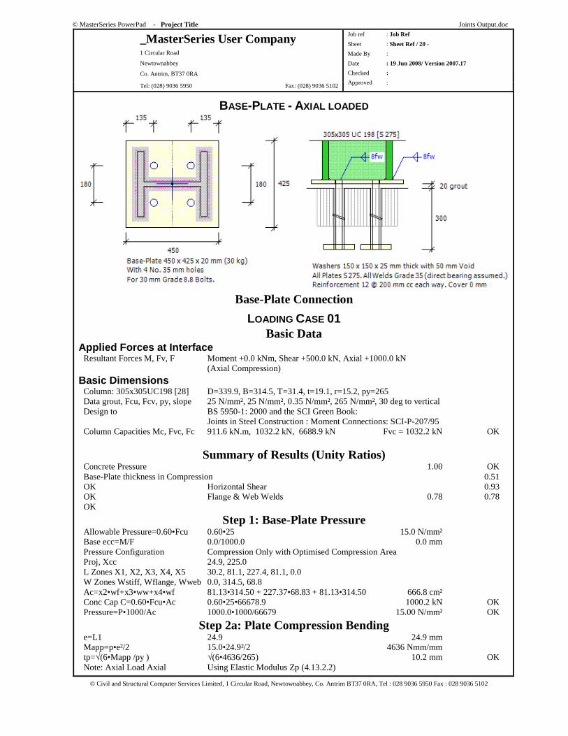
BASE-PLATE - AXIAL LOADED
Base-Plate Connection
LOADING CASE 01 Basic Data
Applied Forces at Interface Resultant Forces M, Fv, F Moment +0.0 kNm, Shear +500.0 kN, Axial +1000.0 kN (Axial Compression)
Basic Dimensions Column: 305x305UC198 [28] D=339.9, B=314.5, T=31.4, t=19.1, r=15.2, py=265 Data grout, Fcu, Fcv, py, slope 25 N/mm², 25 N/mm², 0.35 N/mm², 265 N/mm², 30 deg to vertical Design to BS 5950-1: 2000 and the SCI Green Book: Joints in Steel Construction : Moment Connections: SCI-P-207/95 Column Capacities Mc, Fvc, Fc 911.6 kN.m, 1032.2 kN, 6688.9 kN Fvc = 1032.2 kN OK
Summary of Results (Unity Ratios) Concrete Pressure 1.00 OK Base-Plate thickness in Compression 0.51 OK Horizontal Shear 0.93 OK Flange & Web Welds 0.78 0.78 OK
Step 1: Base-Plate Pressure Allowable Pressure=0.60•Fcu 0.60•25 15.0 N/mm² Base ecc=M/F 0.0/1000.0 0.0 mm Pressure Configuration Compression Only with Optimised Compression Area Proj, Xcc 24.9, 225.0 L Zones X1, X2, X3, X4, X5 30.2, 81.1, 227.4, 81.1, 0.0 W Zones Wstiff, Wflange, Wweb 0.0, 314.5, 68.8 Ac=x2•wf+x3•ww+x4•wf 81.13•314.50 + 227.37•68.83 + 81.13•314.50 666.8 cm² Conc Cap C=0.60•Fcu•Ac 0.60•25•66678.9 1000.2 kN OK Pressure=P•1000/Ac 1000.0•1000/66679 15.00 N/mm² OK
Step 2a: Plate Compression Bending e=L1 24.9 24.9 mm Mapp=p•e²/2 15.0•24.9²/2 4636 Nmm/mm tp=√(6•Mapp /py ) √(6•4636/265) 10.2 mm OK Note: Axial Load Axial Using Elastic Modulus Zp (4.13.2.2)
© MasterSeries PowerPad - Project Title Joints Output.doc
_MasterSeries User Company 1 Circular Road
Newtownabbey
Co. Antrim, BT37 0RA
Tel: (028) 9036 5950 Fax: (028) 9036 5102
Job ref : Job Ref
Sheet : Sheet Ref / 21 -
Made By :
Date : 19 Jun 2008/ Version 2007.17
Checked :
Approved :
© Civil and Structural Computer Services Limited, 1 Circular Road, Newtownabbey, Co. Antrim BT37 0RA, Tel : 028 9036 5950 Fax : 028 9036 5102
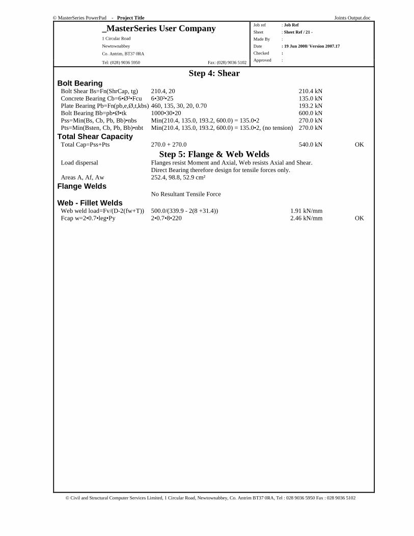
Step 4: Shear Bolt Bearing Bolt Shear Bs=Fn(ShrCap, tg) 210.4, 20 210.4 kN Concrete Bearing Cb=6•Ø²•Fcu 6•30²•25 135.0 kN Plate Bearing Pb=Fn(pb,e,Ø,t,kbs) 460, 135, 30, 20, 0.70 193.2 kN Bolt Bearing Bb=pb•Ø•tk 1000•30•20 600.0 kN Pss=Min(Bs, Cb, Pb, Bb)•nbs Min(210.4, 135.0, 193.2, 600.0) = 135.0•2 270.0 kN Pts=Min(Bsten, Cb, Pb, Bb)•nbt Min(210.4, 135.0, 193.2, 600.0) = 135.0•2, (no tension) 270.0 kN
Total Shear Capacity Total Cap=Pss+Pts 270.0 + 270.0 540.0 kN OK
Step 5: Flange & Web Welds Load dispersal Flanges resist Moment and Axial, Web resists Axial and Shear. Direct Bearing therefore design for tensile forces only. Areas A, Af, Aw 252.4, 98.8, 52.9 cm²
Flange Welds No Resultant Tensile Force
Web - Fillet Welds Web weld load=Fv/(D-2(fw+T)) 500.0/(339.9 - 2(8 +31.4)) 1.91 kN/mm Fcap w=2•0.7•leg•Py 2•0.7•8•220 2.46 kN/mm OK

© MasterSeries PowerPad - Project Title Joints Output.doc
_MasterSeries User Company 1 Circular Road
Newtownabbey
Co. Antrim, BT37 0RA
Tel: (028) 9036 5950 Fax: (028) 9036 5102
Job ref : Job Ref
Sheet : Sheet Ref / 22 -
Made By :
Date : 19 Jun 2008/ Version 2007.17
Checked :
Approved :
© Civil and Structural Computer Services Limited, 1 Circular Road, Newtownabbey, Co. Antrim BT37 0RA, Tel : 028 9036 5950 Fax : 028 9036 5102
COLUMN SPLICE: NON-BEARING
Non Bearing - Column Splice Connection Basic Data
Applied Forces at Interface FC Maximum Factored Axial Load 510.0 kN Compression FCD Minimum Factored Axial Load 0.0 kN Compression M Factored Moment 30.0 kNm FC Factored Shear Force 0.0 kN Column Gap= 10 mm Therefore No direct bearing. HSFG Bolts Non-slip at service) Design to BS 5950: Pt 1: 2000 and the SCI Green Book: Joints in Steel Construction: Simple Connections: SCI-P212: 2002
Basic Dimensions Upper Column-203x203UC46 [28] D=203.2, B=203.6, T=11.0, t=7.2, r=10.2, py=275, Fc =1613 kN Lower Column-203x203UC52 [28] D=206.2, B=204.3, T=12.5, t=7.9, r=10.2, py=275, Fc =1836 kN
Summary of Results (Unity Ratios) Plate & Flange Capacity in Compression 0.62 OK Plate & Flange Capacity in Tension 0.29 OK Flange Bolts Shear Capacity Bolt Capacity 0.78 OK Web Plate Axial Capacity 0.09 OK Upper Web Axial Capacity 0.17 OK Lower Web Axial Capacity 0.15 OK Web Plate Moment Capacity 0.00 OK Web Plate Shear Capacity 0.00 OK Web Bolt Capacity 0.81 OK
Resultant Forces F1p =+M/D+FC • (Af /A) +30.0/203.2 + 510.0•(2239.6/5873.0) 342.1 kN F1n =- M/D+FC • (Af /A) - 30.0/203.2 + 510.0•(2239.6/5873.0) 46.8 kN F2p =+M/D-FCD • (Af /A) +30.0/203.2 + 0.0•(2239.6/5873.0) 147.6 kN F2n =- M/D-FCD • (Af /A) - 30.0/203.2 + 0.0•(2239.6/5873.0) -147.6 kN F1 (comp)=max(0, F1p , F1n , F2p , F2n ) max(0, 342.1,46.8, 147.6, -147.6) 342.1 kN compression F2 (tens)=min(0, F1p , F1n , F2p , F2n )min(0, 342.1,46.8, 147.6, -147.6) -147.6 kN tension
© MasterSeries PowerPad - Project Title Joints Output.doc
_MasterSeries User Company 1 Circular Road
Newtownabbey
Co. Antrim, BT37 0RA
Tel: (028) 9036 5950 Fax: (028) 9036 5102
Job ref : Job Ref
Sheet : Sheet Ref / 23 -
Made By :
Date : 19 Jun 2008/ Version 2007.17
Checked :
Approved :
© Civil and Structural Computer Services Limited, 1 Circular Road, Newtownabbey, Co. Antrim BT37 0RA, Tel : 028 9036 5950 Fax : 028 9036 5102
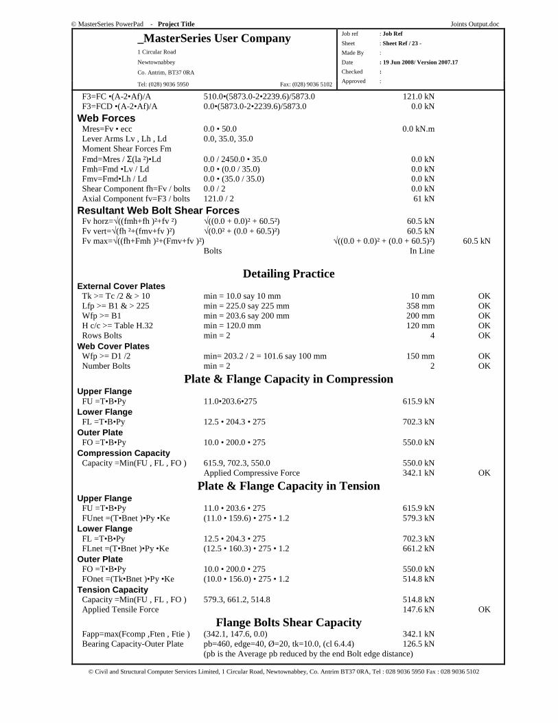
F3=FC •(A-2•Af)/A 510.0•(5873.0-2•2239.6)/5873.0 121.0 kN F3=FCD •(A-2•Af)/A 0.0•(5873.0-2•2239.6)/5873.0 0.0 kN
Web Forces Mres=Fv • ecc 0.0 • 50.0 0.0 kN.m Lever Arms Lv , Lh , Ld 0.0, 35.0, 35.0 Moment Shear Forces Fm Fmd=Mres / Σ(la ²)•Ld 0.0 / 2450.0 • 35.0 0.0 kN Fmh=Fmd •Lv / Ld 0.0 • (0.0 / 35.0) 0.0 kN Fmv=Fmd•Lh / Ld 0.0 • (35.0 / 35.0) 0.0 kN Shear Component fh=Fv / bolts 0.0 / 2 0.0 kN Axial Component fv=F3 / bolts 121.0 / 2 61 kN
Resultant Web Bolt Shear Forces Fv horz=√((fmh+fh )²+fv ²) √((0.0 + 0.0)² + 60.5²) 60.5 kN Fv vert=√(fh ²+(fmv+fv )²) √(0.0² + (0.0 + 60.5)²) 60.5 kN Fv max=√((fh+Fmh )²+(Fmv+fv )²) √((0.0 + 0.0)² + (0.0 + 60.5)²) 60.5 kN Bolts In Line
Detailing Practice External Cover Plates Tk >= Tc /2 & > 10 min = 10.0 say 10 mm 10 mm OK Lfp >= B1 & > 225 min = 225.0 say 225 mm 358 mm OK Wfp >= B1 min = 203.6 say 200 mm 200 mm OK H c/c >= Table H.32 min = 120.0 mm 120 mm OK Rows Bolts min = 2 4 OK Web Cover Plates Wfp >= D1 /2 min= 203.2 / 2 = 101.6 say 100 mm 150 mm OK Number Bolts min = 2 2 OK
Plate & Flange Capacity in Compression Upper Flange FU =T•B•Py 11.0•203.6•275 615.9 kN Lower Flange FL =T•B•Py 12.5 • 204.3 • 275 702.3 kN Outer Plate FO =T•B•Py 10.0 • 200.0 • 275 550.0 kN Compression Capacity Capacity =Min(FU , FL , FO ) 615.9, 702.3, 550.0 550.0 kN Applied Compressive Force 342.1 kN OK
Plate & Flange Capacity in Tension Upper Flange FU =T•B•Py 11.0 • 203.6 • 275 615.9 kN FUnet =(T•Bnet )•Py •Ke (11.0 • 159.6) • 275 • 1.2 579.3 kN Lower Flange FL =T•B•Py 12.5 • 204.3 • 275 702.3 kN FLnet =(T•Bnet )•Py •Ke (12.5 • 160.3) • 275 • 1.2 661.2 kN Outer Plate FO =T•B•Py 10.0 • 200.0 • 275 550.0 kN FOnet =(Tk•Bnet )•Py •Ke (10.0 • 156.0) • 275 • 1.2 514.8 kN Tension Capacity Capacity =Min(FU , FL , FO ) 579.3, 661.2, 514.8 514.8 kN Applied Tensile Force 147.6 kN OK
Flange Bolts Shear Capacity Fapp=max(Fcomp ,Ften , Ftie ) (342.1, 147.6, 0.0) 342.1 kN Bearing Capacity-Outer Plate pb=460, edge=40, Ø=20, tk=10.0, (cl 6.4.4) 126.5 kN (pb is the Average pb reduced by the end Bolt edge distance)
© MasterSeries PowerPad - Project Title Joints Output.doc
_MasterSeries User Company 1 Circular Road
Newtownabbey
Co. Antrim, BT37 0RA
Tel: (028) 9036 5950 Fax: (028) 9036 5102
Job ref : Job Ref
Sheet : Sheet Ref / 24 -
Made By :
Date : 19 Jun 2008/ Version 2007.17
Checked :
Approved :
© Civil and Structural Computer Services Limited, 1 Circular Road, Newtownabbey, Co. Antrim BT37 0RA, Tel : 028 9036 5950 Fax : 028 9036 5102
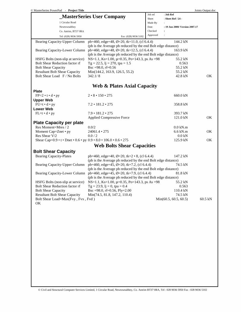
Bearing Capacity-Upper Column pb=460, edge=48, Ø=20, tk=11.0, (cl 6.4.4) 144.2 kN (pb is the Average pb reduced by the end Bolt edge distance) Bearing Capacity-Lower Column pb=460, edge=48, Ø=20, tk=12.5, (cl 6.4.4) 163.9 kN (pb is the Average pb reduced by the end Bolt edge distance) HSFG Bolts (non-slip at service) NS=1.1, Ks=1.00, µ=0.35, Po=143.3, ps As =98 55.2 kN Bolt Shear Reduction factor rf Tg = 22.5, lj = 270, tpa = 1.5 0.563 Bolt Shear Capacity Bsc =98.0, rf=0.56 55.2 kN Resultant Bolt Shear Capacity Min(144.2, 163.9, 126.5, 55.2) 55.2 kN Bolt Shear Load F / No Bolts 342.1/ 8 42.8 kN OK
Web & Plates Axial Capacity Plate FP=2 • t • d • py 2 • 8 • 150 • 275 660.0 kN Upper Web FU=t • d • py 7.2 • 181.2 • 275 358.8 kN Lower Web FL=t • d • py 7.9 • 181.2 • 275 393.7 kN Applied Compressive Force 121.0 kN OK
Plate Capacity per plate Res Moment=Mres / 2 0.0/2 0.0 kN.m Moment Cap=Znet • py 24061.4 • 275 6.6 kN.m OK Res Shear V/2 0.0 / 2 0.0 kN Shear Cap=0.9 • t • Dnet • 0.6 • py 0.9 • 8.0 • 106.0 • 0.6 • 275 125.9 kN OK
Web Bolts Shear Capacities Bolt Shear Capacity Bearing Capacity-Plates pb=460, edge=40, Ø=20, tk=2 • 8, (cl 6.4.4) 147.2 kN (pb is the Average pb reduced by the end Bolt edge distance) Bearing Capacity-Upper Column pb=460, edge=45, Ø=20, tk=7.2, (cl 6.4.4) 74.5 kN (pb is the Average pb reduced by the end Bolt edge distance) Bearing Capacity-Lower Column pb=460, edge=45, Ø=20, tk=7.9, (cl 6.4.4) 81.8 kN (pb is the Average pb reduced by the end Bolt edge distance) HSFG Bolts (non-slip at service) NS=1.1, Ks=1.00, µ=0.35, Po=143.3, ps As =98 55.2 kN Bolt Shear Reduction factor rf Tg = 23.9, lj = 0, tpa = 0.4 0.563 Bolt Shear Capacity Bsc =98.0, rf=0.56, Ply=2.00 110.4 kN Resultant Bolt Shear Capacity Min(74.5, 81.8, 147.2, 110.4) 74.5 kN Bolt Shear Load=Max(Fvy , Fvx , Fvd ) Min(60.5, 60.5, 60.5) 60.5 kN OK
© MasterSeries PowerPad - Project Title Joints Output.doc
_MasterSeries User Company 1 Circular Road
Newtownabbey
Co. Antrim, BT37 0RA
Tel: (028) 9036 5950 Fax: (028) 9036 5102
Job ref : Job Ref
Sheet : Sheet Ref / 25 -
Made By :
Date : 19 Jun 2008/ Version 2007.17
Checked :
Approved :
© Civil and Structural Computer Services Limited, 1 Circular Road, Newtownabbey, Co. Antrim BT37 0RA, Tel : 028 9036 5950 Fax : 028 9036 5102
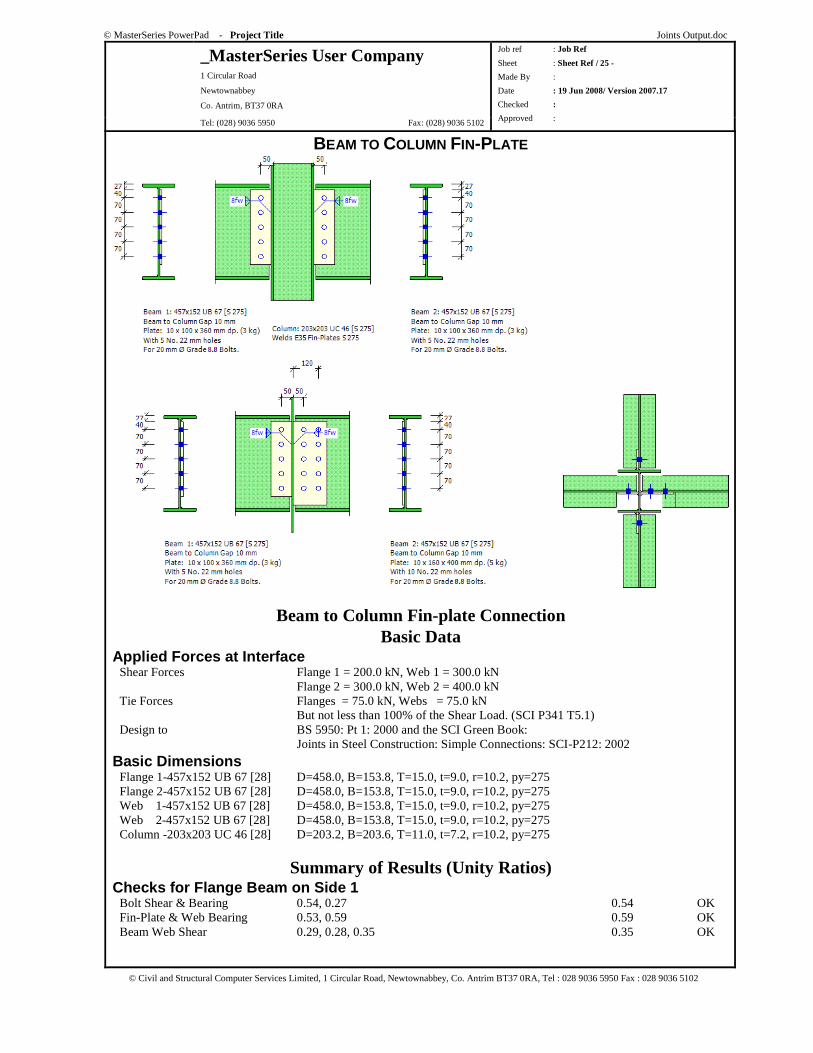
BEAM TO COLUMN FIN-PLATE
Beam to Column Fin-plate Connection Basic Data
Applied Forces at Interface Shear Forces Flange 1 = 200.0 kN, Web 1 = 300.0 kN Flange 2 = 300.0 kN, Web 2 = 400.0 kN Tie Forces Flanges = 75.0 kN, Webs = 75.0 kN But not less than 100% of the Shear Load. (SCI P341 T5.1) Design to BS 5950: Pt 1: 2000 and the SCI Green Book: Joints in Steel Construction: Simple Connections: SCI-P212: 2002
Basic Dimensions Flange 1-457x152 UB 67 [28] D=458.0, B=153.8, T=15.0, t=9.0, r=10.2, py=275 Flange 2-457x152 UB 67 [28] D=458.0, B=153.8, T=15.0, t=9.0, r=10.2, py=275 Web 1-457x152 UB 67 [28] D=458.0, B=153.8, T=15.0, t=9.0, r=10.2, py=275 Web 2-457x152 UB 67 [28] D=458.0, B=153.8, T=15.0, t=9.0, r=10.2, py=275 Column -203x203 UC 46 [28] D=203.2, B=203.6, T=11.0, t=7.2, r=10.2, py=275
Summary of Results (Unity Ratios) Checks for Flange Beam on Side 1 Bolt Shear & Bearing 0.54, 0.27 0.54 OK Fin-Plate & Web Bearing 0.53, 0.59 0.59 OK Beam Web Shear 0.29, 0.28, 0.35 0.35 OK
© MasterSeries PowerPad - Project Title Joints Output.doc
_MasterSeries User Company 1 Circular Road
Newtownabbey
Co. Antrim, BT37 0RA
Tel: (028) 9036 5950 Fax: (028) 9036 5102
Job ref : Job Ref
Sheet : Sheet Ref / 26 -
Made By :
Date : 19 Jun 2008/ Version 2007.17
Checked :
Approved :
© Civil and Structural Computer Services Limited, 1 Circular Road, Newtownabbey, Co. Antrim BT37 0RA, Tel : 028 9036 5950 Fax : 028 9036 5102
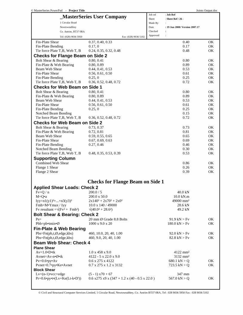
Fin-Plate Shear 0.37, 0.40, 0.33 0.40 OK Fin-Plate Bending 0.17, 0 0.17 OK Tie force Plate T,B, Web T, B 0.24, 0.35, 0.32, 0.48 0.48 OK
Checks for Flange Beam on Side 2 Bolt Shear & Bearing 0.80, 0.41 0.80 OK Fin-Plate & Web Bearing 0.80, 0.89 0.89 OK Beam Web Shear 0.44, 0.41, 0.53 0.53 OK Fin-Plate Shear 0.56, 0.61, 0.50 0.61 OK Fin-Plate Bending 0.25, 0 0.25 OK Tie force Plate T,B, Web T, B 0.36, 0.52, 0.48, 0.72 0.72 OK
Checks for Web Beam on Side 1 Bolt Shear & Bearing 0.80, 0.41 0.80 OK Fin-Plate & Web Bearing 0.80, 0.89 0.89 OK Beam Web Shear 0.44, 0.41, 0.53 0.53 OK Fin-Plate Shear 0.56, 0.61, 0.50 0.61 OK Fin-Plate Bending 0.25, 0 0.25 OK Notched Beam Bending 0.15 OK Tie force Plate T,B, Web T, B 0.36, 0.52, 0.48, 0.72 0.72 OK
Checks for Web Beam on Side 2 Bolt Shear & Bearing 0.73, 0.37 0.73 OK Fin-Plate & Web Bearing 0.72, 0.81 0.81 OK Beam Web Shear 0.59, 0.55, 0.65 0.65 OK Fin-Plate Shear 0.67, 0.69, 0.63 0.69 OK Fin-Plate Bending 0.27, 0.46 0.46 OK Notched Beam Bending 0.30 OK Tie force Plate T,B, Web T, B 0.48, 0.35, 0.53, 0.39 0.53 OK
Supporting Column Combined Web Shear 0.86 OK Flange 1 Shear 0.26 OK Flange 2 Shear 0.39 OK
Checks for Flange Beam on Side 1 Applied Shear Loads: Check 2 Fv=Q / n 200.0 / 5 40.0 kN M=Q•a 200.0 x 50.0 10.0 kN.m Iyy=n1(y1)²+...+n3(y3)² 2x140² + 2x70² + 2x0² 49000 mm² Fmh=M•Ymax / Iyy 10.0 x 140 / 49000 28.6 kN Fv resultant =√(Fv² + Fmh²) √(40.0² + 28.6²) 49.2 kN
Bolt Shear & Bearing: Check 2 Ps= 20 mm Ø Grade 8.8 Bolts 91.9 kN > Fv OK Pbb=pb•tmin•Ø 1000 x 9.0 x 20 180.0 kN > Fv OK
Fin-Plate & Web Bearing Pbs=Fn(pb,t,Ø,edge,kbs) 460, 10.0, 20, 40, 1.00 92.0 kN > Fv OK Pbs=Fn(pb,t,Ø,edge,kbs) 460, 9.0, 20, 40, 1.00 82.8 kN > Fv OK
Beam Web Shear: Check 4 Plane Shear Av=1.0•D•tk 1.0 x 458 x 9.0 4122 mm² Avnet=Av-n•Ø•tk 4122 - 5 x 22.0 x 9.0 3132 mm² Pv=0.6•py•Av 0.6 x 275 x 4122 680.1 kN > Q OK Pvnet=0.7•py•Ke•Avnet 0.7 x 275 x 1.2 x 3132 723.5 kN > Q OK Block Shear Lv=(n-1)•vcc+edge (5 - 1) x70 + 67 347 mm Pr=0.6•py•t•(Lv+Ke(Lt-k•D')) 0.6 x275 x9 x (347 + 1.2 x (40 - 0.5 x 22.0 ) 567.0 kN > Q OK

© MasterSeries PowerPad - Project Title Joints Output.doc
_MasterSeries User Company 1 Circular Road
Newtownabbey
Co. Antrim, BT37 0RA
Tel: (028) 9036 5950 Fax: (028) 9036 5102
Job ref : Job Ref
Sheet : Sheet Ref / 27 -
Made By :
Date : 19 Jun 2008/ Version 2007.17
Checked :
Approved :
© Civil and Structural Computer Services Limited, 1 Circular Road, Newtownabbey, Co. Antrim BT37 0RA, Tel : 028 9036 5950 Fax : 028 9036 5102
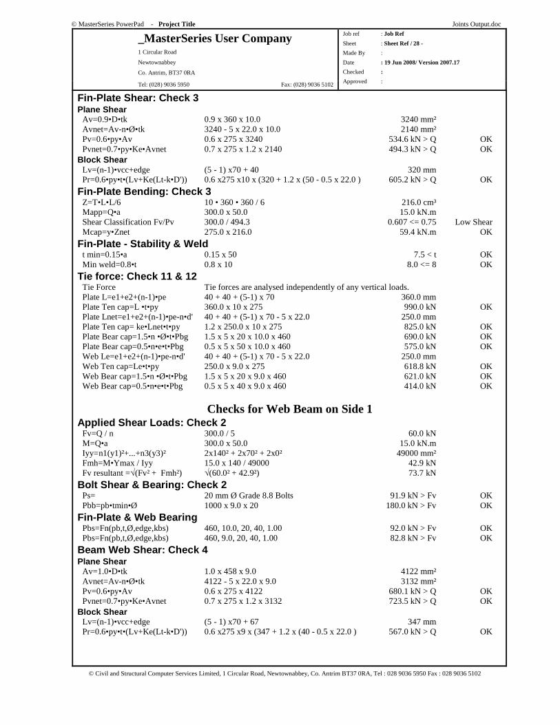
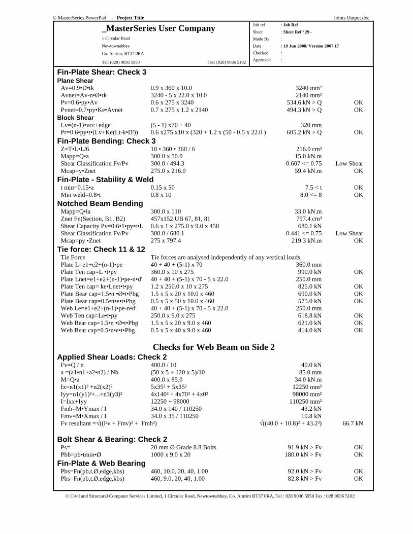
Fin-Plate Shear: Check 3 Plane Shear Av=0.9•D•tk 0.9 x 360 x 10.0 3240 mm² Avnet=Av-n•Ø•tk 3240 - 5 x 22.0 x 10.0 2140 mm² Pv=0.6•py•Av 0.6 x 275 x 3240 534.6 kN > Q OK Pvnet=0.7•py•Ke•Avnet 0.7 x 275 x 1.2 x 2140 494.3 kN > Q OK Block Shear Lv=(n-1)•vcc+edge (5 - 1) x70 + 40 320 mm Pr=0.6•py•t•(Lv+Ke(Lt-k•D')) 0.6 x275 x10 x (320 + 1.2 x (50 - 0.5 x 22.0 ) 605.2 kN > Q OK
Fin-Plate Bending: Check 3 Z=T•L•L/6 10 • 360 • 360 / 6 216.0 cm³ Mapp=Q•a 200.0 x 50.0 10.0 kN.m Shear Classification Fv/Pv 200.0 / 494.3 0.405 <= 0.75 Low Shear Mcap=y•Znet 275.0 x 216.0 59.4 kN.m OK
Fin-Plate - Stability & Weld t min=0.15•a 0.15 x 50 7.5 < t OK Min weld=0.8•t 0.8 x 10 8.0 <= 8 OK
Tie force: Check 11 & 12 Tie Force Tie forces are analysed independently of any vertical loads. Plate L=e1+e2+(n-1)•pe 40 + 40 + (5-1) x 70 360.0 mm Plate Ten cap=L •t•py 360.0 x 10 x 275 990.0 kN OK Plate Lnet=e1+e2+(n-1)•pe-n•d' 40 + 40 + (5-1) x 70 - 5 x 22.0 250.0 mm Plate Ten cap= ke•Lnet•t•py 1.2 x 250.0 x 10 x 275 825.0 kN OK Plate Bear cap=1.5•n •Ø•t•Pbg 1.5 x 5 x 20 x 10.0 x 460 690.0 kN OK Plate Bear cap=0.5•n•e•t•Pbg 0.5 x 5 x 50 x 10.0 x 460 575.0 kN OK Web Le=e1+e2+(n-1)•pe-n•d' 40 + 40 + (5-1) x 70 - 5 x 22.0 250.0 mm Web Ten cap=Le•t•py 250.0 x 9.0 x 275 618.8 kN OK Web Bear cap=1.5•n •Ø•t•Pbg 1.5 x 5 x 20 x 9.0 x 460 621.0 kN OK Web Bear cap=0.5•n•e•t•Pbg 0.5 x 5 x 40 x 9.0 x 460 414.0 kN OK
Checks for Flange Beam on Side 2 Applied Shear Loads: Check 2 Fv=Q / n 300.0 / 5 60.0 kN M=Q•a 300.0 x 50.0 15.0 kN.m Iyy=n1(y1)²+...+n3(y3)² 2x140² + 2x70² + 2x0² 49000 mm² Fmh=M•Ymax / Iyy 15.0 x 140 / 49000 42.9 kN Fv resultant =√(Fv² + Fmh²) √(60.0² + 42.9²) 73.7 kN
Bolt Shear & Bearing: Check 2 Ps= 20 mm Ø Grade 8.8 Bolts 91.9 kN > Fv OK Pbb=pb•tmin•Ø 1000 x 9.0 x 20 180.0 kN > Fv OK
Fin-Plate & Web Bearing Pbs=Fn(pb,t,Ø,edge,kbs) 460, 10.0, 20, 40, 1.00 92.0 kN > Fv OK Pbs=Fn(pb,t,Ø,edge,kbs) 460, 9.0, 20, 40, 1.00 82.8 kN > Fv OK
Beam Web Shear: Check 4 Plane Shear Av=1.0•D•tk 1.0 x 458 x 9.0 4122 mm² Avnet=Av-n•Ø•tk 4122 - 5 x 22.0 x 9.0 3132 mm² Pv=0.6•py•Av 0.6 x 275 x 4122 680.1 kN > Q OK Pvnet=0.7•py•Ke•Avnet 0.7 x 275 x 1.2 x 3132 723.5 kN > Q OK Block Shear Lv=(n-1)•vcc+edge (5 - 1) x70 + 67 347 mm Pr=0.6•py•t•(Lv+Ke(Lt-k•D')) 0.6 x275 x9 x (347 + 1.2 x (40 - 0.5 x 22.0 ) 567.0 kN > Q OK
© MasterSeries PowerPad - Project Title Joints Output.doc
_MasterSeries User Company 1 Circular Road
Newtownabbey
Co. Antrim, BT37 0RA
Tel: (028) 9036 5950 Fax: (028) 9036 5102
Job ref : Job Ref
Sheet : Sheet Ref / 28 -
Made By :
Date : 19 Jun 2008/ Version 2007.17
Checked :
Approved :
© Civil and Structural Computer Services Limited, 1 Circular Road, Newtownabbey, Co. Antrim BT37 0RA, Tel : 028 9036 5950 Fax : 028 9036 5102
Fin-Plate Shear: Check 3 Plane Shear Av=0.9•D•tk 0.9 x 360 x 10.0 3240 mm² Avnet=Av-n•Ø•tk 3240 - 5 x 22.0 x 10.0 2140 mm² Pv=0.6•py•Av 0.6 x 275 x 3240 534.6 kN > Q OK Pvnet=0.7•py•Ke•Avnet 0.7 x 275 x 1.2 x 2140 494.3 kN > Q OK Block Shear Lv=(n-1)•vcc+edge (5 - 1) x70 + 40 320 mm Pr=0.6•py•t•(Lv+Ke(Lt-k•D')) 0.6 x275 x10 x (320 + 1.2 x (50 - 0.5 x 22.0 ) 605.2 kN > Q OK
Fin-Plate Bending: Check 3 Z=T•L•L/6 10 • 360 • 360 / 6 216.0 cm³ Mapp=Q•a 300.0 x 50.0 15.0 kN.m Shear Classification Fv/Pv 300.0 / 494.3 0.607 <= 0.75 Low Shear Mcap=y•Znet 275.0 x 216.0 59.4 kN.m OK
Fin-Plate - Stability & Weld t min=0.15•a 0.15 x 50 7.5 < t OK Min weld=0.8•t 0.8 x 10 8.0 <= 8 OK
Tie force: Check 11 & 12 Tie Force Tie forces are analysed independently of any vertical loads. Plate L=e1+e2+(n-1)•pe 40 + 40 + (5-1) x 70 360.0 mm Plate Ten cap=L •t•py 360.0 x 10 x 275 990.0 kN OK Plate Lnet=e1+e2+(n-1)•pe-n•d' 40 + 40 + (5-1) x 70 - 5 x 22.0 250.0 mm Plate Ten cap= ke•Lnet•t•py 1.2 x 250.0 x 10 x 275 825.0 kN OK Plate Bear cap=1.5•n •Ø•t•Pbg 1.5 x 5 x 20 x 10.0 x 460 690.0 kN OK Plate Bear cap=0.5•n•e•t•Pbg 0.5 x 5 x 50 x 10.0 x 460 575.0 kN OK Web Le=e1+e2+(n-1)•pe-n•d' 40 + 40 + (5-1) x 70 - 5 x 22.0 250.0 mm Web Ten cap=Le•t•py 250.0 x 9.0 x 275 618.8 kN OK Web Bear cap=1.5•n •Ø•t•Pbg 1.5 x 5 x 20 x 9.0 x 460 621.0 kN OK Web Bear cap=0.5•n•e•t•Pbg 0.5 x 5 x 40 x 9.0 x 460 414.0 kN OK
Checks for Web Beam on Side 1 Applied Shear Loads: Check 2 Fv=Q / n 300.0 / 5 60.0 kN M=Q•a 300.0 x 50.0 15.0 kN.m Iyy=n1(y1)²+...+n3(y3)² 2x140² + 2x70² + 2x0² 49000 mm² Fmh=M•Ymax / Iyy 15.0 x 140 / 49000 42.9 kN Fv resultant =√(Fv² + Fmh²) √(60.0² + 42.9²) 73.7 kN
Bolt Shear & Bearing: Check 2 Ps= 20 mm Ø Grade 8.8 Bolts 91.9 kN > Fv OK Pbb=pb•tmin•Ø 1000 x 9.0 x 20 180.0 kN > Fv OK
Fin-Plate & Web Bearing Pbs=Fn(pb,t,Ø,edge,kbs) 460, 10.0, 20, 40, 1.00 92.0 kN > Fv OK Pbs=Fn(pb,t,Ø,edge,kbs) 460, 9.0, 20, 40, 1.00 82.8 kN > Fv OK
Beam Web Shear: Check 4 Plane Shear Av=1.0•D•tk 1.0 x 458 x 9.0 4122 mm² Avnet=Av-n•Ø•tk 4122 - 5 x 22.0 x 9.0 3132 mm² Pv=0.6•py•Av 0.6 x 275 x 4122 680.1 kN > Q OK Pvnet=0.7•py•Ke•Avnet 0.7 x 275 x 1.2 x 3132 723.5 kN > Q OK Block Shear Lv=(n-1)•vcc+edge (5 - 1) x70 + 67 347 mm Pr=0.6•py•t•(Lv+Ke(Lt-k•D')) 0.6 x275 x9 x (347 + 1.2 x (40 - 0.5 x 22.0 ) 567.0 kN > Q OK
© MasterSeries PowerPad - Project Title Joints Output.doc
_MasterSeries User Company 1 Circular Road
Newtownabbey
Co. Antrim, BT37 0RA
Tel: (028) 9036 5950 Fax: (028) 9036 5102
Job ref : Job Ref
Sheet : Sheet Ref / 29 -
Made By :
Date : 19 Jun 2008/ Version 2007.17
Checked :
Approved :
© Civil and Structural Computer Services Limited, 1 Circular Road, Newtownabbey, Co. Antrim BT37 0RA, Tel : 028 9036 5950 Fax : 028 9036 5102
Fin-Plate Shear: Check 3 Plane Shear Av=0.9•D•tk 0.9 x 360 x 10.0 3240 mm² Avnet=Av-n•Ø•tk 3240 - 5 x 22.0 x 10.0 2140 mm² Pv=0.6•py•Av 0.6 x 275 x 3240 534.6 kN > Q OK Pvnet=0.7•py•Ke•Avnet 0.7 x 275 x 1.2 x 2140 494.3 kN > Q OK Block Shear Lv=(n-1)•vcc+edge (5 - 1) x70 + 40 320 mm Pr=0.6•py•t•(Lv+Ke(Lt-k•D')) 0.6 x275 x10 x (320 + 1.2 x (50 - 0.5 x 22.0 ) 605.2 kN > Q OK
Fin-Plate Bending: Check 3 Z=T•L•L/6 10 • 360 • 360 / 6 216.0 cm³ Mapp=Q•a 300.0 x 50.0 15.0 kN.m Shear Classification Fv/Pv 300.0 / 494.3 0.607 <= 0.75 Low Shear Mcap=y•Znet 275.0 x 216.0 59.4 kN.m OK
Fin-Plate - Stability & Weld t min=0.15•a 0.15 x 50 7.5 < t OK Min weld=0.8•t 0.8 x 10 8.0 <= 8 OK
Notched Beam Bending Mapp=Q•la 300.0 x 110 33.0 kN.m Znet Fn(Section, B1, B2) 457x152 UB 67, 81, 81 797.4 cm³ Shear Capacity Pv=0.6•1•py•t•L 0.6 x 1 x 275.0 x 9.0 x 458 680.1 kN Shear Classification Fv/Pv 300.0 / 680.1 0.441 <= 0.75 Low Shear Mcap=py •Znet 275 x 797.4 219.3 kN.m OK
Tie force: Check 11 & 12 Tie Force Tie forces are analysed independently of any vertical loads. Plate L=e1+e2+(n-1)•pe 40 + 40 + (5-1) x 70 360.0 mm Plate Ten cap=L •t•py 360.0 x 10 x 275 990.0 kN OK Plate Lnet=e1+e2+(n-1)•pe-n•d' 40 + 40 + (5-1) x 70 - 5 x 22.0 250.0 mm Plate Ten cap= ke•Lnet•t•py 1.2 x 250.0 x 10 x 275 825.0 kN OK Plate Bear cap=1.5•n •Ø•t•Pbg 1.5 x 5 x 20 x 10.0 x 460 690.0 kN OK Plate Bear cap=0.5•n•e•t•Pbg 0.5 x 5 x 50 x 10.0 x 460 575.0 kN OK Web Le=e1+e2+(n-1)•pe-n•d' 40 + 40 + (5-1) x 70 - 5 x 22.0 250.0 mm Web Ten cap=Le•t•py 250.0 x 9.0 x 275 618.8 kN OK Web Bear cap=1.5•n •Ø•t•Pbg 1.5 x 5 x 20 x 9.0 x 460 621.0 kN OK Web Bear cap=0.5•n•e•t•Pbg 0.5 x 5 x 40 x 9.0 x 460 414.0 kN OK
Checks for Web Beam on Side 2 Applied Shear Loads: Check 2 Fv=Q / n 400.0 / 10 40.0 kN a =(a1•n1+a2•n2) / Nb (50 x 5 + 120 x 5)/10 85.0 mm M=Q•a 400.0 x 85.0 34.0 kN.m Ix=n1(x1)² +n2(x2)² 5x35² + 5x35² 12250 mm² Iyy=n1(y1)²+...+n3(y3)² 4x140² + 4x70² + 4x0² 98000 mm² I=Ixx+Iyy 12250 + 98000 110250 mm² Fmh=M•Ymax / I 34.0 x 140 / 110250 43.2 kN Fmv=M•Xmax / I 34.0 x 35 / 110250 10.8 kN Fv resultant =√((Fv + Fmv)² + Fmh²) √((40.0 + 10.8)² + 43.2²) 66.7 kN
Bolt Shear & Bearing: Check 2 Ps= 20 mm Ø Grade 8.8 Bolts 91.9 kN > Fv OK Pbb=pb•tmin•Ø 1000 x 9.0 x 20 180.0 kN > Fv OK
Fin-Plate & Web Bearing Pbs=Fn(pb,t,Ø,edge,kbs) 460, 10.0, 20, 40, 1.00 92.0 kN > Fv OK Pbs=Fn(pb,t,Ø,edge,kbs) 460, 9.0, 20, 40, 1.00 82.8 kN > Fv OK
© MasterSeries PowerPad - Project Title Joints Output.doc
_MasterSeries User Company 1 Circular Road
Newtownabbey
Co. Antrim, BT37 0RA
Tel: (028) 9036 5950 Fax: (028) 9036 5102
Job ref : Job Ref
Sheet : Sheet Ref / 30 -
Made By :
Date : 19 Jun 2008/ Version 2007.17
Checked :
Approved :
© Civil and Structural Computer Services Limited, 1 Circular Road, Newtownabbey, Co. Antrim BT37 0RA, Tel : 028 9036 5950 Fax : 028 9036 5102
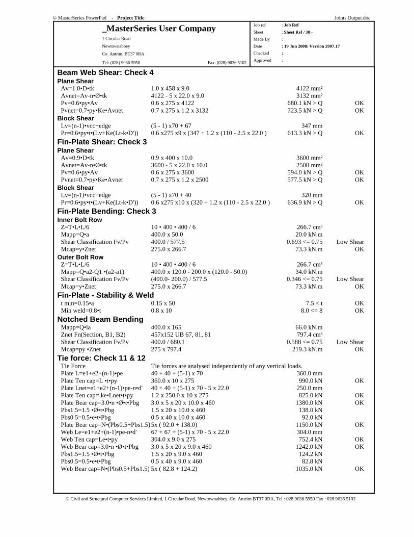
Beam Web Shear: Check 4 Plane Shear Av=1.0•D•tk 1.0 x 458 x 9.0 4122 mm² Avnet=Av-n•Ø•tk 4122 - 5 x 22.0 x 9.0 3132 mm² Pv=0.6•py•Av 0.6 x 275 x 4122 680.1 kN > Q OK Pvnet=0.7•py•Ke•Avnet 0.7 x 275 x 1.2 x 3132 723.5 kN > Q OK Block Shear Lv=(n-1)•vcc+edge (5 - 1) x70 + 67 347 mm Pr=0.6•py•t•(Lv+Ke(Lt-k•D')) 0.6 x275 x9 x (347 + 1.2 x (110 - 2.5 x 22.0 ) 613.3 kN > Q OK
Fin-Plate Shear: Check 3 Plane Shear Av=0.9•D•tk 0.9 x 400 x 10.0 3600 mm² Avnet=Av-n•Ø•tk 3600 - 5 x 22.0 x 10.0 2500 mm² Pv=0.6•py•Av 0.6 x 275 x 3600 594.0 kN > Q OK Pvnet=0.7•py•Ke•Avnet 0.7 x 275 x 1.2 x 2500 577.5 kN > Q OK Block Shear Lv=(n-1)•vcc+edge (5 - 1) x70 + 40 320 mm Pr=0.6•py•t•(Lv+Ke(Lt-k•D')) 0.6 x275 x10 x (320 + 1.2 x (110 - 2.5 x 22.0 ) 636.9 kN > Q OK
Fin-Plate Bending: Check 3 Inner Bolt Row Z=T•L•L/6 10 • 400 • 400 / 6 266.7 cm³ Mapp=Q•a 400.0 x 50.0 20.0 kN.m Shear Classification Fv/Pv 400.0 / 577.5 0.693 <= 0.75 Low Shear Mcap=y•Znet 275.0 x 266.7 73.3 kN.m OK Outer Bolt Row Z=T•L•L/6 10 • 400 • 400 / 6 266.7 cm³ Mapp=Q•a2-Q1 •(a2-a1) 400.0 x 120.0 - 200.0 x (120.0 - 50.0) 34.0 kN.m Shear Classification Fv/Pv (400.0- 200.0) / 577.5 0.346 <= 0.75 Low Shear Mcap=y•Znet 275.0 x 266.7 73.3 kN.m OK
Fin-Plate - Stability & Weld t min=0.15•a 0.15 x 50 7.5 < t OK Min weld=0.8•t 0.8 x 10 8.0 <= 8 OK
Notched Beam Bending Mapp=Q•la 400.0 x 165 66.0 kN.m Znet Fn(Section, B1, B2) 457x152 UB 67, 81, 81 797.4 cm³ Shear Classification Fv/Pv 400.0 / 680.1 0.588 <= 0.75 Low Shear Mcap=py •Znet 275 x 797.4 219.3 kN.m OK
Tie force: Check 11 & 12 Tie Force Tie forces are analysed independently of any vertical loads. Plate L=e1+e2+(n-1)•pe 40 + 40 + (5-1) x 70 360.0 mm Plate Ten cap=L •t•py 360.0 x 10 x 275 990.0 kN OK Plate Lnet=e1+e2+(n-1)•pe-n•d' 40 + 40 + (5-1) x 70 - 5 x 22.0 250.0 mm Plate Ten cap= ke•Lnet•t•py 1.2 x 250.0 x 10 x 275 825.0 kN OK Plate Bear cap=3.0•n •Ø•t•Pbg 3.0 x 5 x 20 x 10.0 x 460 1380.0 kN OK Pbs1.5=1.5 •Ø•t•Pbg 1.5 x 20 x 10.0 x 460 138.0 kN Pbs0.5=0.5•e•t•Pbg 0.5 x 40 x 10.0 x 460 92.0 kN Plate Bear cap=N•(Pbs0.5+Pbs1.5) 5x ( 92.0 + 138.0) 1150.0 kN OK Web Le=e1+e2+(n-1)•pe-n•d' 67 + 67 + (5-1) x 70 - 5 x 22.0 304.0 mm Web Ten cap=Le•t•py 304.0 x 9.0 x 275 752.4 kN OK Web Bear cap=3.0•n •Ø•t•Pbg 3.0 x 5 x 20 x 9.0 x 460 1242.0 kN OK Pbs1.5=1.5 •Ø•t•Pbg 1.5 x 20 x 9.0 x 460 124.2 kN Pbs0.5=0.5•e•t•Pbg 0.5 x 40 x 9.0 x 460 82.8 kN Web Bear cap=N•(Pbs0.5+Pbs1.5) 5x ( 82.8 + 124.2) 1035.0 kN OK

© MasterSeries PowerPad - Project Title Joints Output.doc
_MasterSeries User Company 1 Circular Road
Newtownabbey
Co. Antrim, BT37 0RA
Tel: (028) 9036 5950 Fax: (028) 9036 5102
Job ref : Job Ref
Sheet : Sheet Ref / 31 -
Made By :
Date : 19 Jun 2008/ Version 2007.17
Checked :
Approved :
© Civil and Structural Computer Services Limited, 1 Circular Road, Newtownabbey, Co. Antrim BT37 0RA, Tel : 028 9036 5950 Fax : 028 9036 5102
Supporting Column Combined Web Shear: Check 10 Qmax=Fn(Q1, Q2, Q2a, L1, L2) 300, 400, 360, 360, 400 660.0 kN Pv=2•0.6•py•(0.9•L1•t) 2 x 0.6 x 275 x (0.9 x 360.0 x 7.2) 769.8 kN > Qmax OK
Flange 1 Shear: Check 10 Qmax=Q 200 200.0 kN Pv=2•0.6•py•(0.9•L1•t) 2 x 0.6 x 275 x (0.9 x 360.0 x 7.2) 769.8 kN > Qmax OK
Punching Shear: Check 10 Tcons=Tw •Usc /Pyf 7.2•410 /275 10.7 mm Trigor=Tw •Usc /fb 7.2•410 /46 63.8 mm Tf <= max(Trigor ,Tcons ) 10<=63.8 OK
Flange 2 Shear: Check 10 Qmax=Q 300 300.0 kN Pv=2•0.6•py•(0.9•L1•t) 2 x 0.6 x 275 x (0.9 x 360.0 x 7.2) 769.8 kN > Qmax OK
Punching Shear: Check 10 Tcons=Tw •Usc /Pyf 7.2•410 /275 10.7 mm Trigor=Tw •Usc /fb 7.2•410 /69 42.5 mm Tf <= max(Trigor ,Tcons ) 10<=42.5 OK
© MasterSeries PowerPad - Project Title Joints Output.doc
_MasterSeries User Company 1 Circular Road
Newtownabbey
Co. Antrim, BT37 0RA
Tel: (028) 9036 5950 Fax: (028) 9036 5102
Job ref : Job Ref
Sheet : Sheet Ref / 32 -
Made By :
Date : 19 Jun 2008/ Version 2007.17
Checked :
Approved :
© Civil and Structural Computer Services Limited, 1 Circular Road, Newtownabbey, Co. Antrim BT37 0RA, Tel : 028 9036 5950 Fax : 028 9036 5102
EAVES JOINT - EXTENDED END PLATE
Beam to Column Flange End-Plated Connection
LOADING CASE 01 Basic Data
Applied Forces at Column/Right Rafter Interface Right Rafter Forces M, Fvr, Fr -330.0 kNm, +300.0 kN, -200.0 kN Resultant Forces M, Fv, F -330.0 kNm, +260.7 kN, -249.1 kN Load directions Bottom of Joint in Tension, Rafter moving Down and in Tension. Design to BS 5950-1: 2000 and the SCI Green Book: Joints in Steel Construction : Moment Connections: SCI-P-207/95 Rafter Capacities Mc, Fvc, Fc 1046.2 kN.m, 1262.3 kN, 3395.2 kN Mc = 1046.2 kN.m OK
Summary of Results (Unity Ratios) Tensile Capacity 0.33 OK Moment Capacity 435.7 kNm (for 4 rows of bolts) (Modified Applied Moment Mm=365.0 kNm) 0.84 OK Moment Capacity 399.3 kNm (for the 3 rows of bolts required in the tension zone) 0.91 OK Shear Capacity 0.23 OK Shear Capacity (Fv & T) 0.18 OK Column Tension Stiffener at row 0 0.00, 0.16, 0.01, 0.05, 0.24 0.24 OK Column Tension Stiffener at row 5 0.00, 0.00, 0.00, 0.00, 0.00 0.00 OK Beam Tension Stiffener at row 3 0.00, 0.10, 0.04, 0.09, 0.19 0.19 OK Flange Welds 0.74 0.74 OK Web Welds 0.56, 0.27 0.56 OK Haunch Welds 0.06, 0.81, 0.23 0.81 OK Column Compression stiff Web Weld 0.16 0.16 OK Beam compression stiffener 0.98 OK
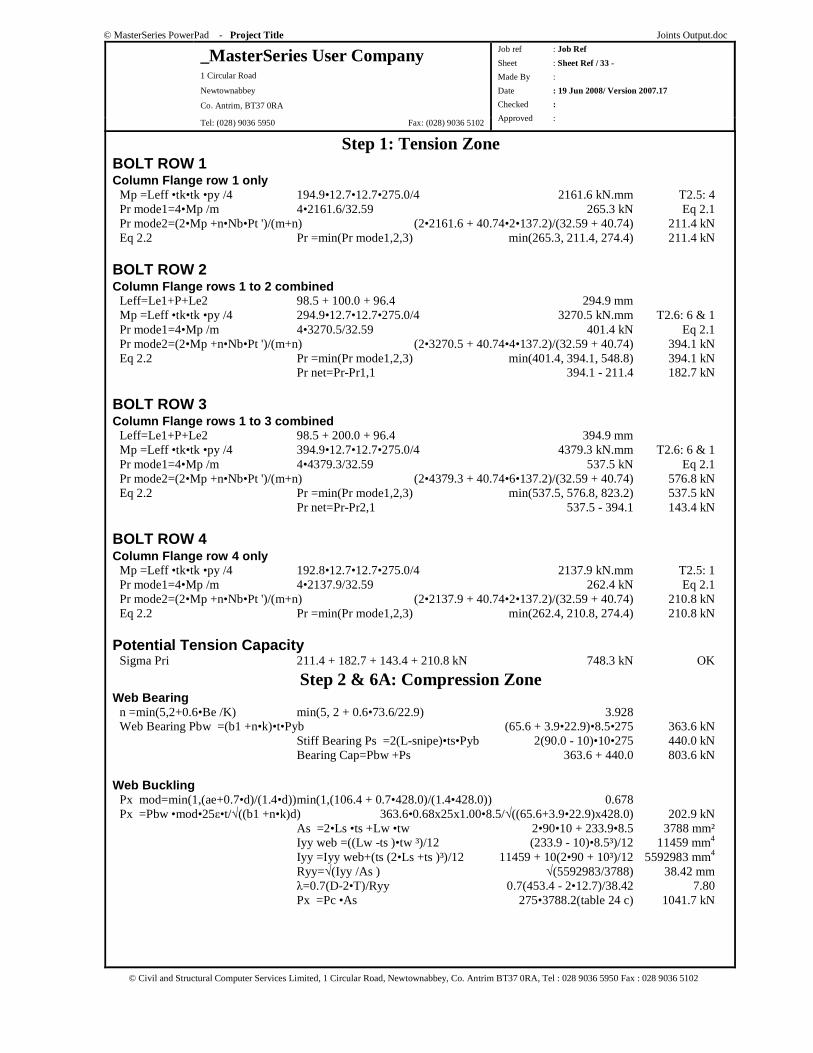
© MasterSeries PowerPad - Project Title Joints Output.doc
_MasterSeries User Company 1 Circular Road
Newtownabbey
Co. Antrim, BT37 0RA
Tel: (028) 9036 5950 Fax: (028) 9036 5102
Job ref : Job Ref
Sheet : Sheet Ref / 33 -
Made By :
Date : 19 Jun 2008/ Version 2007.17
Checked :
Approved :
© Civil and Structural Computer Services Limited, 1 Circular Road, Newtownabbey, Co. Antrim BT37 0RA, Tel : 028 9036 5950 Fax : 028 9036 5102
Step 1: Tension Zone BOLT ROW 1 Column Flange row 1 only Mp =Leff •tk•tk •py /4 194.9•12.7•12.7•275.0/4 2161.6 kN.mm T2.5: 4 Pr mode1=4•Mp /m 4•2161.6/32.59 265.3 kN Eq 2.1 Pr mode2=(2•Mp +n•Nb•Pt ')/(m+n) (2•2161.6 + 40.74•2•137.2)/(32.59 + 40.74) 211.4 kN Eq 2.2 Pr =min(Pr mode1,2,3) min(265.3, 211.4, 274.4) 211.4 kN
BOLT ROW 2 Column Flange rows 1 to 2 combined Leff=Le1+P+Le2 98.5 + 100.0 + 96.4 294.9 mm Mp =Leff •tk•tk •py /4 294.9•12.7•12.7•275.0/4 3270.5 kN.mm T2.6: 6 & 1 Pr mode1=4•Mp /m 4•3270.5/32.59 401.4 kN Eq 2.1 Pr mode2=(2•Mp +n•Nb•Pt ')/(m+n) (2•3270.5 + 40.74•4•137.2)/(32.59 + 40.74) 394.1 kN Eq 2.2 Pr =min(Pr mode1,2,3) min(401.4, 394.1, 548.8) 394.1 kN Pr net=Pr-Pr1,1 394.1 - 211.4 182.7 kN
BOLT ROW 3 Column Flange rows 1 to 3 combined Leff=Le1+P+Le2 98.5 + 200.0 + 96.4 394.9 mm Mp =Leff •tk•tk •py /4 394.9•12.7•12.7•275.0/4 4379.3 kN.mm T2.6: 6 & 1 Pr mode1=4•Mp /m 4•4379.3/32.59 537.5 kN Eq 2.1 Pr mode2=(2•Mp +n•Nb•Pt ')/(m+n) (2•4379.3 + 40.74•6•137.2)/(32.59 + 40.74) 576.8 kN Eq 2.2 Pr =min(Pr mode1,2,3) min(537.5, 576.8, 823.2) 537.5 kN Pr net=Pr-Pr2,1 537.5 - 394.1 143.4 kN
BOLT ROW 4 Column Flange row 4 only Mp =Leff •tk•tk •py /4 192.8•12.7•12.7•275.0/4 2137.9 kN.mm T2.5: 1 Pr mode1=4•Mp /m 4•2137.9/32.59 262.4 kN Eq 2.1 Pr mode2=(2•Mp +n•Nb•Pt ')/(m+n) (2•2137.9 + 40.74•2•137.2)/(32.59 + 40.74) 210.8 kN Eq 2.2 Pr =min(Pr mode1,2,3) min(262.4, 210.8, 274.4) 210.8 kN
Potential Tension Capacity Sigma Pri 211.4 + 182.7 + 143.4 + 210.8 kN 748.3 kN OK
Step 2 & 6A: Compression Zone Web Bearing n =min(5,2+0.6•Be /K) min(5, 2 + 0.6•73.6/22.9) 3.928 Web Bearing Pbw =(b1 +n•k)•t•Pyb (65.6 + 3.9•22.9)•8.5•275 363.6 kN Stiff Bearing Ps =2(L-snipe)•ts•Pyb 2(90.0 - 10)•10•275 440.0 kN Bearing Cap=Pbw +Ps 363.6 + 440.0 803.6 kN Web Buckling Px mod=min(1,(ae+0.7•d)/(1.4•d)) min(1,(106.4 + 0.7•428.0)/(1.4•428.0)) 0.678 Px =Pbw •mod•25ε•t/√((b1 +n•k)d) 363.6•0.68x25x1.00•8.5/√((65.6+3.9•22.9)x428.0) 202.9 kN As =2•Ls •ts +Lw •tw 2•90•10 + 233.9•8.5 3788 mm² Iyy web =((Lw -ts )•tw ³)/12 (233.9 - 10)•8.5³)/12 11459 mm4
Iyy =Iyy web+(ts (2•Ls +ts )³)/12 11459 + 10(2•90 + 10³)/12 5592983 mm4
Ryy=√(Iyy /As ) √(5592983/3788) 38.42 mm λ=0.7(D-2•T)/Ryy 0.7(453.4 - 2•12.7)/38.42 7.80 Px =Pc •As 275•3788.2(table 24 c) 1041.7 kN
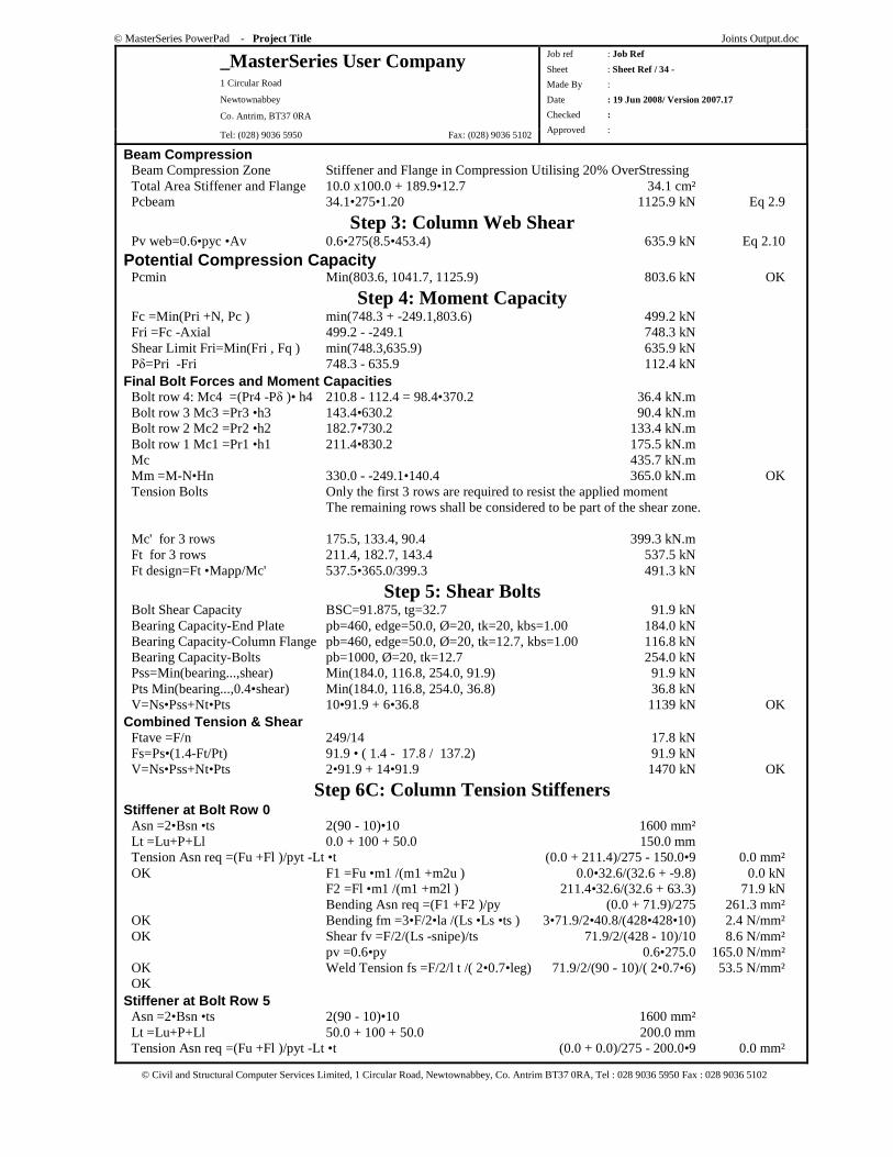
© MasterSeries PowerPad - Project Title Joints Output.doc
_MasterSeries User Company 1 Circular Road
Newtownabbey
Co. Antrim, BT37 0RA
Tel: (028) 9036 5950 Fax: (028) 9036 5102
Job ref : Job Ref
Sheet : Sheet Ref / 34 -
Made By :
Date : 19 Jun 2008/ Version 2007.17
Checked :
Approved :
© Civil and Structural Computer Services Limited, 1 Circular Road, Newtownabbey, Co. Antrim BT37 0RA, Tel : 028 9036 5950 Fax : 028 9036 5102
Beam Compression Beam Compression Zone Stiffener and Flange in Compression Utilising 20% OverStressing Total Area Stiffener and Flange 10.0 x100.0 + 189.9•12.7 34.1 cm² Pcbeam 34.1•275•1.20 1125.9 kN Eq 2.9
Step 3: Column Web Shear Pv web=0.6•pyc •Av 0.6•275(8.5•453.4) 635.9 kN Eq 2.10
Potential Compression Capacity Pcmin Min(803.6, 1041.7, 1125.9) 803.6 kN OK
Step 4: Moment Capacity Fc =Min(Pri +N, Pc ) min(748.3 + -249.1,803.6) 499.2 kN Fri =Fc -Axial 499.2 - -249.1 748.3 kN Shear Limit Fri=Min(Fri , Fq ) min(748.3,635.9) 635.9 kN Pδ=Pri -Fri 748.3 - 635.9 112.4 kN Final Bolt Forces and Moment Capacities Bolt row 4: Mc4 =(Pr4 -Pδ )• h4 210.8 - 112.4 = 98.4•370.2 36.4 kN.m Bolt row 3 Mc3 =Pr3 •h3 143.4•630.2 90.4 kN.m Bolt row 2 Mc2 =Pr2 •h2 182.7•730.2 133.4 kN.m Bolt row 1 Mc1 =Pr1 •h1 211.4•830.2 175.5 kN.m Mc 435.7 kN.m Mm =M-N•Hn 330.0 - -249.1•140.4 365.0 kN.m OK Tension Bolts Only the first 3 rows are required to resist the applied moment The remaining rows shall be considered to be part of the shear zone. Mc' for 3 rows 175.5, 133.4, 90.4 399.3 kN.m Ft for 3 rows 211.4, 182.7, 143.4 537.5 kN Ft design=Ft •Mapp/Mc' 537.5•365.0/399.3 491.3 kN
Step 5: Shear Bolts Bolt Shear Capacity BSC=91.875, tg=32.7 91.9 kN Bearing Capacity-End Plate pb=460, edge=50.0, Ø=20, tk=20, kbs=1.00 184.0 kN Bearing Capacity-Column Flange pb=460, edge=50.0, Ø=20, tk=12.7, kbs=1.00 116.8 kN Bearing Capacity-Bolts pb=1000, Ø=20, tk=12.7 254.0 kN Pss=Min(bearing...,shear) Min(184.0, 116.8, 254.0, 91.9) 91.9 kN Pts Min(bearing...,0.4•shear) Min(184.0, 116.8, 254.0, 36.8) 36.8 kN V=Ns•Pss+Nt•Pts 10•91.9 + 6•36.8 1139 kN OK Combined Tension & Shear Ftave =F/n 249/14 17.8 kN Fs=Ps•(1.4-Ft/Pt) 91.9 • ( 1.4 - 17.8 / 137.2) 91.9 kN V=Ns•Pss+Nt•Pts 2•91.9 + 14•91.9 1470 kN OK
Step 6C: Column Tension Stiffeners Stiffener at Bolt Row 0 Asn =2•Bsn •ts 2(90 - 10)•10 1600 mm² Lt =Lu+P+Ll 0.0 + 100 + 50.0 150.0 mm Tension Asn req =(Fu +Fl )/pyt -Lt •t (0.0 + 211.4)/275 - 150.0•9 0.0 mm² OK F1 =Fu •m1 /(m1 +m2u ) 0.0•32.6/(32.6 + -9.8) 0.0 kN F2 =Fl •m1 /(m1 +m2l ) 211.4•32.6/(32.6 + 63.3) 71.9 kN Bending Asn req =(F1 +F2 )/py (0.0 + 71.9)/275 261.3 mm² OK Bending fm =3•F/2•la /(Ls •Ls •ts ) 3•71.9/2•40.8/(428•428•10) 2.4 N/mm² OK Shear fv =F/2/(Ls -snipe)/ts 71.9/2/(428 - 10)/10 8.6 N/mm² pv =0.6•py 0.6•275.0 165.0 N/mm² OK Weld Tension fs =F/2/l t /( 2•0.7•leg) 71.9/2/(90 - 10)/( 2•0.7•6) 53.5 N/mm² OK Stiffener at Bolt Row 5 Asn =2•Bsn •ts 2(90 - 10)•10 1600 mm² Lt =Lu+P+Ll 50.0 + 100 + 50.0 200.0 mm Tension Asn req =(Fu +Fl )/pyt -Lt •t (0.0 + 0.0)/275 - 200.0•9 0.0 mm²
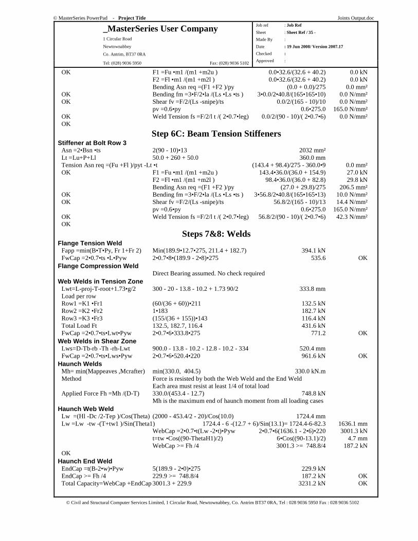
© MasterSeries PowerPad - Project Title Joints Output.doc
_MasterSeries User Company 1 Circular Road
Newtownabbey
Co. Antrim, BT37 0RA
Tel: (028) 9036 5950 Fax: (028) 9036 5102
Job ref : Job Ref
Sheet : Sheet Ref / 35 -
Made By :
Date : 19 Jun 2008/ Version 2007.17
Checked :
Approved :
© Civil and Structural Computer Services Limited, 1 Circular Road, Newtownabbey, Co. Antrim BT37 0RA, Tel : 028 9036 5950 Fax : 028 9036 5102
OK F1 =Fu •m1 /(m1 +m2u ) 0.0•32.6/(32.6 + 40.2) 0.0 kN F2 =Fl •m1 /(m1 +m2l ) 0.0•32.6/(32.6 + 40.2) 0.0 kN Bending Asn req =(F1 +F2 )/py (0.0 + 0.0)/275 0.0 mm² OK Bending fm =3•F/2•la /(Ls •Ls •ts ) 3•0.0/2•40.8/(165•165•10) 0.0 N/mm² OK Shear fv =F/2/(Ls -snipe)/ts 0.0/2/(165 - 10)/10 0.0 N/mm² pv =0.6•py 0.6•275.0 165.0 N/mm² OK Weld Tension fs =F/2/l t /( 2•0.7•leg) 0.0/2/(90 - 10)/( 2•0.7•6) 0.0 N/mm² OK
Step 6C: Beam Tension Stiffeners Stiffener at Bolt Row 3 Asn =2•Bsn •ts 2(90 - 10)•13 2032 mm² Lt =Lu+P+Ll 50.0 + 260 + 50.0 360.0 mm Tension Asn req =(Fu +Fl )/pyt -Lt •t (143.4 + 98.4)/275 - 360.0•9 0.0 mm² OK F1 =Fu •m1 /(m1 +m2u ) 143.4•36.0/(36.0 + 154.9) 27.0 kN F2 =Fl •m1 /(m1 +m2l ) 98.4•36.0/(36.0 + 82.8) 29.8 kN Bending Asn req =(F1 +F2 )/py (27.0 + 29.8)/275 206.5 mm² OK Bending fm =3•F/2•la /(Ls •Ls •ts ) 3•56.8/2•40.8/(165•165•13) 10.0 N/mm² OK Shear fv =F/2/(Ls -snipe)/ts 56.8/2/(165 - 10)/13 14.4 N/mm² pv =0.6•py 0.6•275.0 165.0 N/mm² OK Weld Tension fs =F/2/l t /( 2•0.7•leg) 56.8/2/(90 - 10)/( 2•0.7•6) 42.3 N/mm² OK
Steps 7&8: Welds Flange Tension Weld Fapp =min(B•T•Py, Fr 1+Fr 2) Min(189.9•12.7•275, 211.4 + 182.7) 394.1 kN FwCap =2•0.7•ts •L•Pyw 2•0.7•8•(189.9 - 2•8)•275 535.6 OK Flange Compression Weld Direct Bearing assumed. No check required Web Welds in Tension Zone Lwt=L-proj-T-root+1.73•g/2 300 - 20 - 13.8 - 10.2 + 1.73 90/2 333.8 mm Load per row Row1 =K1 •Fr1 (60/(36 + 60))•211 132.5 kN Row2 =K2 •Fr2 1•183 182.7 kN Row3 =K3 •Fr3 (155/(36 + 155))•143 116.4 kN Total Load Ft 132.5, 182.7, 116.4 431.6 kN FwCap =2•0.7•ts•Lwt•Pyw 2•0.7•6•333.8•275 771.2 OK Web Welds in Shear Zone Lws=D-Tb-rb -Th -rh-Lwt 900.0 - 13.8 - 10.2 - 12.8 - 10.2 - 334 520.4 mm FwCap =2•0.7•ts•Lws•Pyw 2•0.7•6•520.4•220 961.6 kN OK Haunch Welds Mh= min(Mappeaves ,Mcrafter) min(330.0, 404.5) 330.0 kN.m Method Force is resisted by both the Web Weld and the End Weld Each area must resist at least 1/4 of total load Applied Force Fh =Mh /(D-T) 330.0/(453.4 - 12.7) 748.8 kN Mh is the maximum end of haunch moment from all loading cases Haunch Web Weld Lw =(Hl -Dc /2-Tep )/Cos(Τheta) (2000 - 453.4/2 - 20)/Cos(10.0) 1724.4 mm Lw =Lw -tw -(T+tw1 )/Sin(Theta1) 1724.4 - 6 -(12.7 + 6)/Sin(13.1)= 1724.4-6-82.3 1636.1 mm WebCap =2•0.7•t(Lw -2•t)•Pyw 2•0.7•6(1636.1 - 2•6)•220 3001.3 kN t=tw •Cos((90-ThetaH1)/2) 6•Cos((90-13.1)/2) 4.7 mm WebCap >= Fh /4 3001.3 >= 748.8/4 187.2 kN OK Haunch End Weld EndCap =t(B-2•w)•Pyw 5(189.9 - 2•0)•275 229.9 kN EndCap >= Fh /4 229.9 >= 748.8/4 187.2 kN OK Total Capacity=WebCap +EndCap 3001.3 + 229.9 3231.2 kN OK
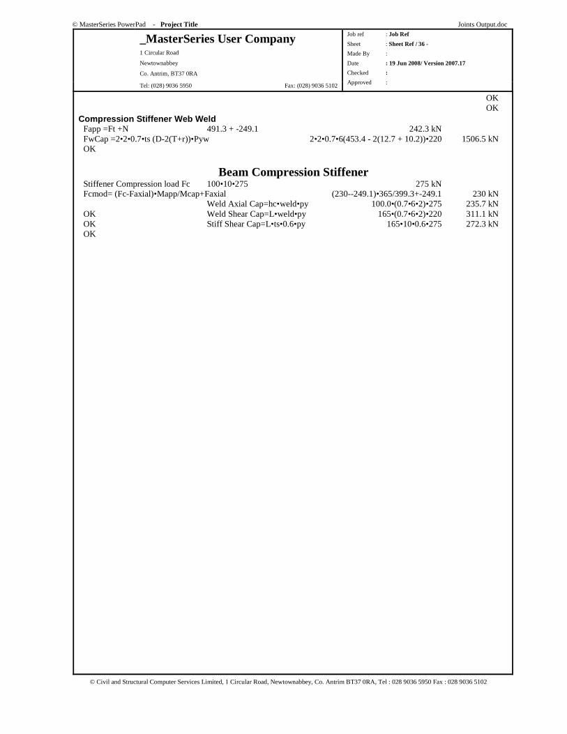
© MasterSeries PowerPad - Project Title Joints Output.doc
_MasterSeries User Company 1 Circular Road
Newtownabbey
Co. Antrim, BT37 0RA
Tel: (028) 9036 5950 Fax: (028) 9036 5102
Job ref : Job Ref
Sheet : Sheet Ref / 36 -
Made By :
Date : 19 Jun 2008/ Version 2007.17
Checked :
Approved :
© Civil and Structural Computer Services Limited, 1 Circular Road, Newtownabbey, Co. Antrim BT37 0RA, Tel : 028 9036 5950 Fax : 028 9036 5102
OK OK Compression Stiffener Web Weld Fapp =Ft +N 491.3 + -249.1 242.3 kN FwCap =2•2•0.7•ts (D-2(T+r))•Pyw 2•2•0.7•6(453.4 - 2(12.7 + 10.2))•220 1506.5 kN OK
Beam Compression Stiffener Stiffener Compression load Fc 100•10•275 275 kN Fcmod= (Fc-Faxial)•Mapp/Mcap+Faxial (230--249.1)•365/399.3+-249.1 230 kN Weld Axial Cap=hc•weld•py 100.0•(0.7•6•2)•275 235.7 kN OK Weld Shear Cap=L•weld•py 165•(0.7•6•2)•220 311.1 kN OK Stiff Shear Cap=L•ts•0.6•py 165•10•0.6•275 272.3 kN OK
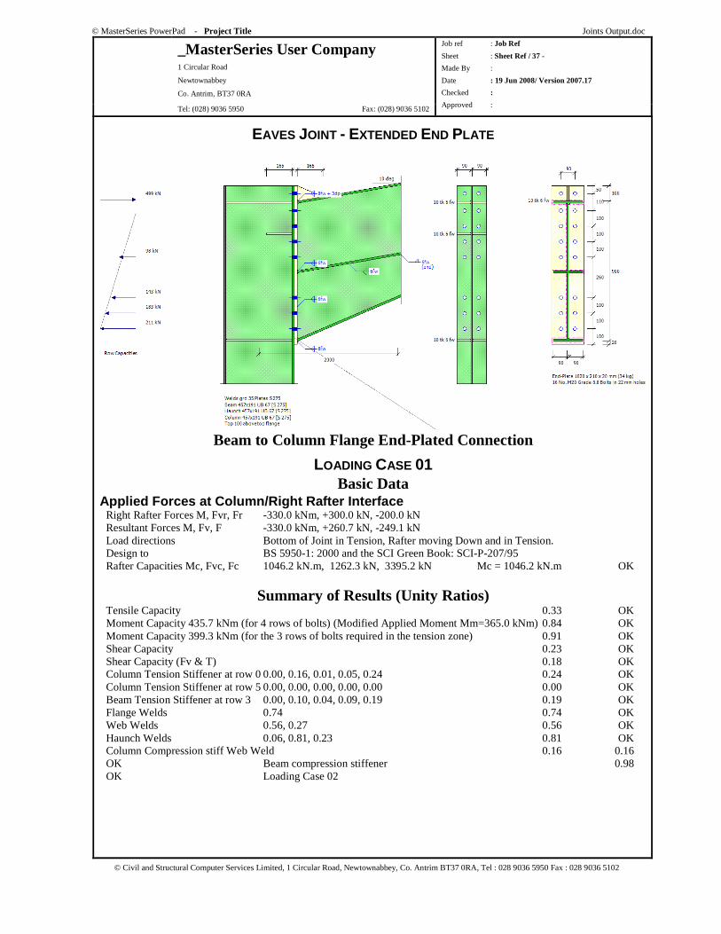
© MasterSeries PowerPad - Project Title Joints Output.doc
_MasterSeries User Company 1 Circular Road
Newtownabbey
Co. Antrim, BT37 0RA
Tel: (028) 9036 5950 Fax: (028) 9036 5102
Job ref : Job Ref
Sheet : Sheet Ref / 37 -
Made By :
Date : 19 Jun 2008/ Version 2007.17
Checked :
Approved :
© Civil and Structural Computer Services Limited, 1 Circular Road, Newtownabbey, Co. Antrim BT37 0RA, Tel : 028 9036 5950 Fax : 028 9036 5102
EAVES JOINT - EXTENDED END PLATE
Beam to Column Flange End-Plated Connection
LOADING CASE 01 Basic Data
Applied Forces at Column/Right Rafter Interface Right Rafter Forces M, Fvr, Fr -330.0 kNm, +300.0 kN, -200.0 kN Resultant Forces M, Fv, F -330.0 kNm, +260.7 kN, -249.1 kN Load directions Bottom of Joint in Tension, Rafter moving Down and in Tension. Design to BS 5950-1: 2000 and the SCI Green Book: SCI-P-207/95 Rafter Capacities Mc, Fvc, Fc 1046.2 kN.m, 1262.3 kN, 3395.2 kN Mc = 1046.2 kN.m OK
Summary of Results (Unity Ratios) Tensile Capacity 0.33 OK Moment Capacity 435.7 kNm (for 4 rows of bolts) (Modified Applied Moment Mm=365.0 kNm) 0.84 OK Moment Capacity 399.3 kNm (for the 3 rows of bolts required in the tension zone) 0.91 OK Shear Capacity 0.23 OK Shear Capacity (Fv & T) 0.18 OK Column Tension Stiffener at row 0 0.00, 0.16, 0.01, 0.05, 0.24 0.24 OK Column Tension Stiffener at row 5 0.00, 0.00, 0.00, 0.00, 0.00 0.00 OK Beam Tension Stiffener at row 3 0.00, 0.10, 0.04, 0.09, 0.19 0.19 OK Flange Welds 0.74 0.74 OK Web Welds 0.56, 0.27 0.56 OK Haunch Welds 0.06, 0.81, 0.23 0.81 OK Column Compression stiff Web Weld 0.16 0.16 OK Beam compression stiffener 0.98 OK Loading Case 02
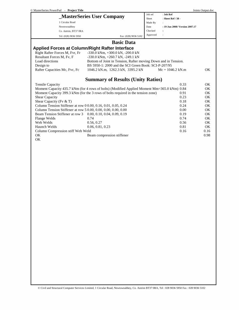
© MasterSeries PowerPad - Project Title Joints Output.doc
_MasterSeries User Company 1 Circular Road
Newtownabbey
Co. Antrim, BT37 0RA
Tel: (028) 9036 5950 Fax: (028) 9036 5102
Job ref : Job Ref
Sheet : Sheet Ref / 38 -
Made By :
Date : 19 Jun 2008/ Version 2007.17
Checked :
Approved :
© Civil and Structural Computer Services Limited, 1 Circular Road, Newtownabbey, Co. Antrim BT37 0RA, Tel : 028 9036 5950 Fax : 028 9036 5102
Basic Data Applied Forces at Column/Right Rafter Interface Right Rafter Forces M, Fvr, Fr -330.0 kNm, +300.0 kN, -200.0 kN Resultant Forces M, Fv, F -330.0 kNm, +260.7 kN, -249.1 kN Load directions Bottom of Joint in Tension, Rafter moving Down and in Tension. Design to BS 5950-1: 2000 and the SCI Green Book: SCI-P-207/95 Rafter Capacities Mc, Fvc, Fc 1046.2 kN.m, 1262.3 kN, 3395.2 kN Mc = 1046.2 kN.m OK
Summary of Results (Unity Ratios) Tensile Capacity 0.33 OK Moment Capacity 435.7 kNm (for 4 rows of bolts) (Modified Applied Moment Mm=365.0 kNm) 0.84 OK Moment Capacity 399.3 kNm (for the 3 rows of bolts required in the tension zone) 0.91 OK Shear Capacity 0.23 OK Shear Capacity (Fv & T) 0.18 OK Column Tension Stiffener at row 0 0.00, 0.16, 0.01, 0.05, 0.24 0.24 OK Column Tension Stiffener at row 5 0.00, 0.00, 0.00, 0.00, 0.00 0.00 OK Beam Tension Stiffener at row 3 0.00, 0.10, 0.04, 0.09, 0.19 0.19 OK Flange Welds 0.74 0.74 OK Web Welds 0.56, 0.27 0.56 OK Haunch Welds 0.06, 0.81, 0.23 0.81 OK Column Compression stiff Web Weld 0.16 0.16 OK Beam compression stiffener 0.98 OK
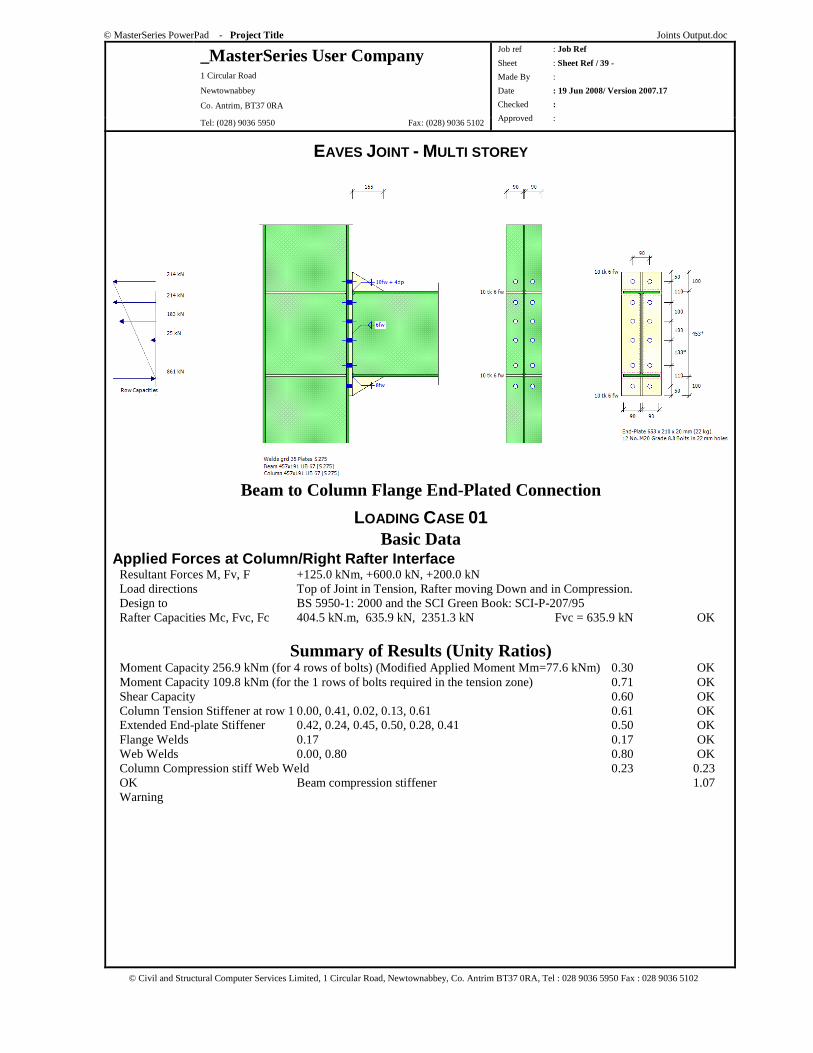
© MasterSeries PowerPad - Project Title Joints Output.doc
_MasterSeries User Company 1 Circular Road
Newtownabbey
Co. Antrim, BT37 0RA
Tel: (028) 9036 5950 Fax: (028) 9036 5102
Job ref : Job Ref
Sheet : Sheet Ref / 39 -
Made By :
Date : 19 Jun 2008/ Version 2007.17
Checked :
Approved :
© Civil and Structural Computer Services Limited, 1 Circular Road, Newtownabbey, Co. Antrim BT37 0RA, Tel : 028 9036 5950 Fax : 028 9036 5102
EAVES JOINT - MULTI STOREY
Beam to Column Flange End-Plated Connection
LOADING CASE 01 Basic Data
Applied Forces at Column/Right Rafter Interface Resultant Forces M, Fv, F +125.0 kNm, +600.0 kN, +200.0 kN Load directions Top of Joint in Tension, Rafter moving Down and in Compression. Design to BS 5950-1: 2000 and the SCI Green Book: SCI-P-207/95 Rafter Capacities Mc, Fvc, Fc 404.5 kN.m, 635.9 kN, 2351.3 kN Fvc = 635.9 kN OK
Summary of Results (Unity Ratios) Moment Capacity 256.9 kNm (for 4 rows of bolts) (Modified Applied Moment Mm=77.6 kNm) 0.30 OK Moment Capacity 109.8 kNm (for the 1 rows of bolts required in the tension zone) 0.71 OK Shear Capacity 0.60 OK Column Tension Stiffener at row 1 0.00, 0.41, 0.02, 0.13, 0.61 0.61 OK Extended End-plate Stiffener 0.42, 0.24, 0.45, 0.50, 0.28, 0.41 0.50 OK Flange Welds 0.17 0.17 OK Web Welds 0.00, 0.80 0.80 OK Column Compression stiff Web Weld 0.23 0.23 OK Beam compression stiffener 1.07 Warning
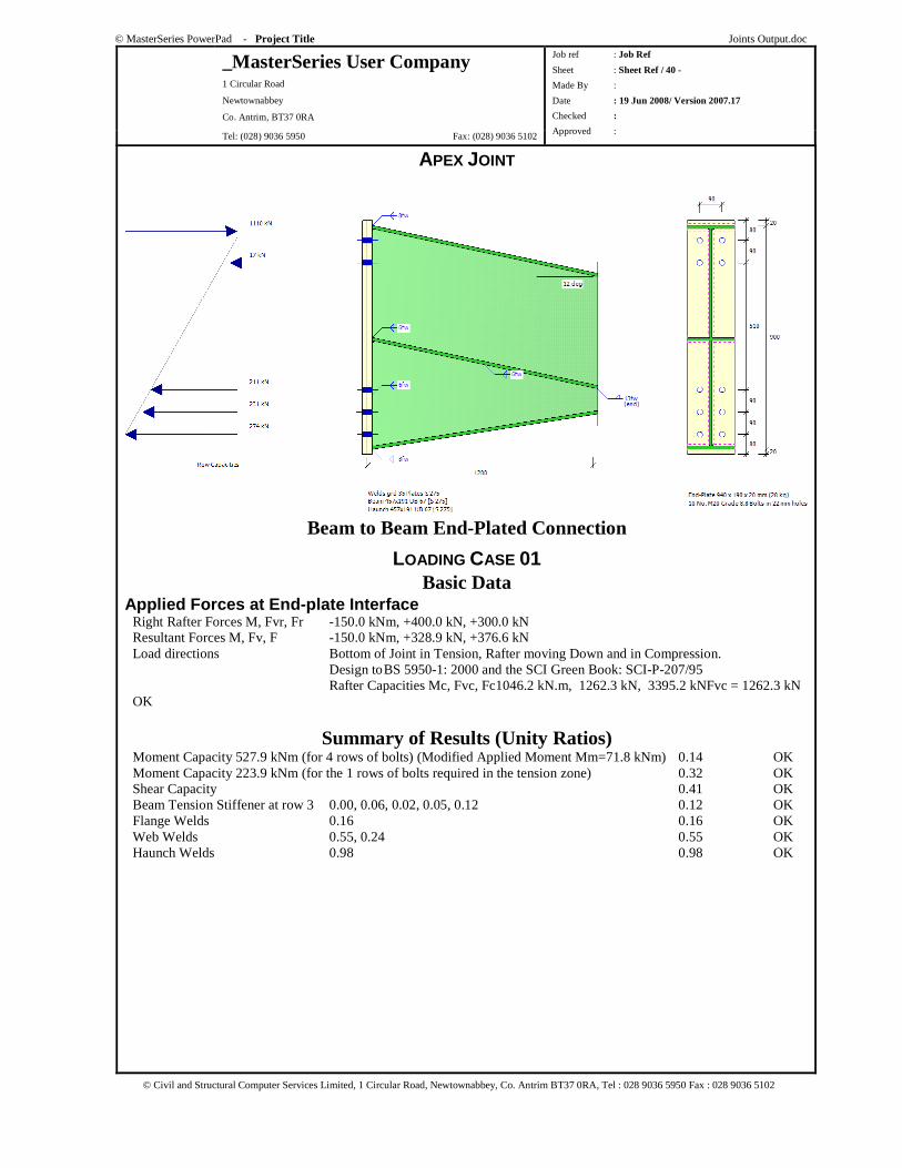
© MasterSeries PowerPad - Project Title Joints Output.doc
_MasterSeries User Company 1 Circular Road
Newtownabbey
Co. Antrim, BT37 0RA
Tel: (028) 9036 5950 Fax: (028) 9036 5102
Job ref : Job Ref
Sheet : Sheet Ref / 40 -
Made By :
Date : 19 Jun 2008/ Version 2007.17
Checked :
Approved :
© Civil and Structural Computer Services Limited, 1 Circular Road, Newtownabbey, Co. Antrim BT37 0RA, Tel : 028 9036 5950 Fax : 028 9036 5102
APEX JOINT
Beam to Beam End-Plated Connection
LOADING CASE 01 Basic Data
Applied Forces at End-plate Interface Right Rafter Forces M, Fvr, Fr -150.0 kNm, +400.0 kN, +300.0 kN Resultant Forces M, Fv, F -150.0 kNm, +328.9 kN, +376.6 kN Load directions Bottom of Joint in Tension, Rafter moving Down and in Compression. Design to BS 5950-1: 2000 and the SCI Green Book: SCI-P-207/95 Rafter Capacities Mc, Fvc, Fc1046.2 kN.m, 1262.3 kN, 3395.2 kNFvc = 1262.3 kN OK
Summary of Results (Unity Ratios) Moment Capacity 527.9 kNm (for 4 rows of bolts) (Modified Applied Moment Mm=71.8 kNm) 0.14 OK Moment Capacity 223.9 kNm (for the 1 rows of bolts required in the tension zone) 0.32 OK Shear Capacity 0.41 OK Beam Tension Stiffener at row 3 0.00, 0.06, 0.02, 0.05, 0.12 0.12 OK Flange Welds 0.16 0.16 OK Web Welds 0.55, 0.24 0.55 OK Haunch Welds 0.98 0.98 OK
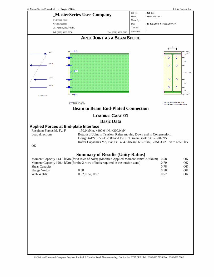
© MasterSeries PowerPad - Project Title Joints Output.doc
_MasterSeries User Company 1 Circular Road
Newtownabbey
Co. Antrim, BT37 0RA
Tel: (028) 9036 5950 Fax: (028) 9036 5102
Job ref : Job Ref
Sheet : Sheet Ref / 41 -
Made By :
Date : 19 Jun 2008/ Version 2007.17
Checked :
Approved :
© Civil and Structural Computer Services Limited, 1 Circular Road, Newtownabbey, Co. Antrim BT37 0RA, Tel : 028 9036 5950 Fax : 028 9036 5102
APEX JOINT AS A BEAM SPLICE
Beam to Beam End-Plated Connection
LOADING CASE 01 Basic Data
Applied Forces at End-plate Interface Resultant Forces M, Fv, F -150.0 kNm, +400.0 kN, +300.0 kN Load directions Bottom of Joint in Tension, Rafter moving Down and in Compression. Design to BS 5950-1: 2000 and the SCI Green Book: SCI-P-207/95 Rafter Capacities Mc, Fvc, Fc 404.5 kN.m, 635.9 kN, 2351.3 kN Fvc = 635.9 kN OK
Summary of Results (Unity Ratios) Moment Capacity 144.5 kNm (for 3 rows of bolts) (Modified Applied Moment Mm=83.9 kNm) 0.58 OK Moment Capacity 120.4 kNm (for the 2 rows of bolts required in the tension zone) 0.70 OK Shear Capacity 0.78 OK Flange Welds 0.58 0.58 OK Web Welds 0.52, 0.52, 0.57 0.57 OK
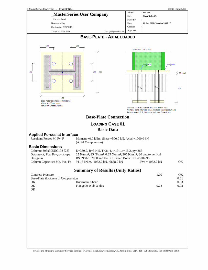
© MasterSeries PowerPad - Project Title Joints Output.doc
_MasterSeries User Company 1 Circular Road
Newtownabbey
Co. Antrim, BT37 0RA
Tel: (028) 9036 5950 Fax: (028) 9036 5102
Job ref : Job Ref
Sheet : Sheet Ref / 42 -
Made By :
Date : 19 Jun 2008/ Version 2007.17
Checked :
Approved :
© Civil and Structural Computer Services Limited, 1 Circular Road, Newtownabbey, Co. Antrim BT37 0RA, Tel : 028 9036 5950 Fax : 028 9036 5102
BASE-PLATE - AXIAL LOADED
Base-Plate Connection
LOADING CASE 01 Basic Data
Applied Forces at Interface Resultant Forces M, Fv, F Moment +0.0 kNm, Shear +500.0 kN, Axial +1000.0 kN (Axial Compression)
Basic Dimensions Column: 305x305UC198 [28] D=339.9, B=314.5, T=31.4, t=19.1, r=15.2, py=265 Data grout, Fcu, Fcv, py, slope 25 N/mm², 25 N/mm², 0.35 N/mm², 265 N/mm², 30 deg to vertical Design to BS 5950-1: 2000 and the SCI Green Book: SCI-P-207/95 Column Capacities Mc, Fvc, Fc 911.6 kN.m, 1032.2 kN, 6688.9 kN Fvc = 1032.2 kN OK
Summary of Results (Unity Ratios) Concrete Pressure 1.00 OK Base-Plate thickness in Compression 0.51 OK Horizontal Shear 0.93 OK Flange & Web Welds 0.78 0.78 OK
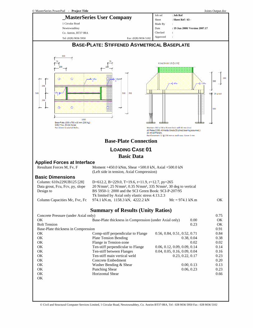
© MasterSeries PowerPad - Project Title Joints Output.doc
_MasterSeries User Company 1 Circular Road
Newtownabbey
Co. Antrim, BT37 0RA
Tel: (028) 9036 5950 Fax: (028) 9036 5102
Job ref : Job Ref
Sheet : Sheet Ref / 43 -
Made By :
Date : 19 Jun 2008/ Version 2007.17
Checked :
Approved :
© Civil and Structural Computer Services Limited, 1 Circular Road, Newtownabbey, Co. Antrim BT37 0RA, Tel : 028 9036 5950 Fax : 028 9036 5102
BASE-PLATE: STIFFENED ASYMETRICAL BASEPLATE
Base-Plate Connection
LOADING CASE 01 Basic Data
Applied Forces at Interface Resultant Forces M, Fv, F Moment +450.0 kNm, Shear +500.0 kN, Axial +500.0 kN (Left side in tension, Axial Compression)
Basic Dimensions Column: 610x229UB125 [28] D=612.2, B=229.0, T=19.6, t=11.9, r=12.7, py=265 Data grout, Fcu, Fcv, py, slope 20 N/mm², 25 N/mm², 0.35 N/mm², 335 N/mm², 30 deg to vertical Design to BS 5950-1: 2000 and the SCI Green Book: SCI-P-207/95 Tk limited by Axial only elastic stress 4.13.2.3 Column Capacities Mc, Fvc, Fc 974.1 kN.m, 1158.3 kN, 4222.2 kN Mc = 974.1 kN.m OK
Summary of Results (Unity Ratios) Concrete Pressure (under Axial only) 0.75 OK Base-Plate thickness in Compression (under Axial only) 0.00 OK Bolt Tension 0.23 OK Base-Plate thickness in Compression 0.91 OK Comp-stiff perpendicular to Flange 0.56, 0.84, 0.51, 0.52, 0.71 0.84 OK Plate Tension Bending 0.38, 0.04 0.38 OK Flange in Tension-zone 0.02 0.02 OK Ten-stiff perpendicular to Flange 0.06, 0.12, 0.09, 0.09, 0.14 0.14 OK Ten-stiff between Flanges 0.04, 0.05, 0.16, 0.09, 0.04 0.16 OK Ten-stiff main vertical weld 0.23, 0.22, 0.17 0.23 OK Concrete Embedment 0.20 OK Washer Bending & Shear 0.00, 0.13 0.13 OK Punching Shear 0.06, 0.23 0.23 OK Horizontal Shear 0.66 OK
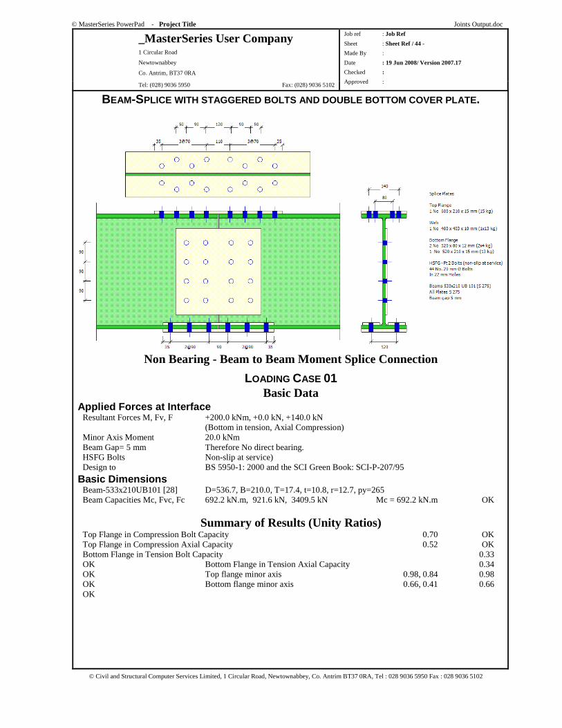
© MasterSeries PowerPad - Project Title Joints Output.doc
_MasterSeries User Company 1 Circular Road
Newtownabbey
Co. Antrim, BT37 0RA
Tel: (028) 9036 5950 Fax: (028) 9036 5102
Job ref : Job Ref
Sheet : Sheet Ref / 44 -
Made By :
Date : 19 Jun 2008/ Version 2007.17
Checked :
Approved :
© Civil and Structural Computer Services Limited, 1 Circular Road, Newtownabbey, Co. Antrim BT37 0RA, Tel : 028 9036 5950 Fax : 028 9036 5102
BEAM-SPLICE WITH STAGGERED BOLTS AND DOUBLE BOTTOM COVER PLATE.
Non Bearing - Beam to Beam Moment Splice Connection
LOADING CASE 01 Basic Data
Applied Forces at Interface Resultant Forces M, Fv, F +200.0 kNm, +0.0 kN, +140.0 kN (Bottom in tension, Axial Compression) Minor Axis Moment 20.0 kNm Beam Gap= 5 mm Therefore No direct bearing. HSFG Bolts Non-slip at service) Design to BS 5950-1: 2000 and the SCI Green Book: SCI-P-207/95
Basic Dimensions Beam-533x210UB101 [28] D=536.7, B=210.0, T=17.4, t=10.8, r=12.7, py=265 Beam Capacities Mc, Fvc, Fc 692.2 kN.m, 921.6 kN, 3409.5 kN Mc = 692.2 kN.m OK
Summary of Results (Unity Ratios) Top Flange in Compression Bolt Capacity 0.70 OK Top Flange in Compression Axial Capacity 0.52 OK Bottom Flange in Tension Bolt Capacity 0.33 OK Bottom Flange in Tension Axial Capacity 0.34 OK Top flange minor axis 0.98, 0.84 0.98 OK Bottom flange minor axis 0.66, 0.41 0.66 OK
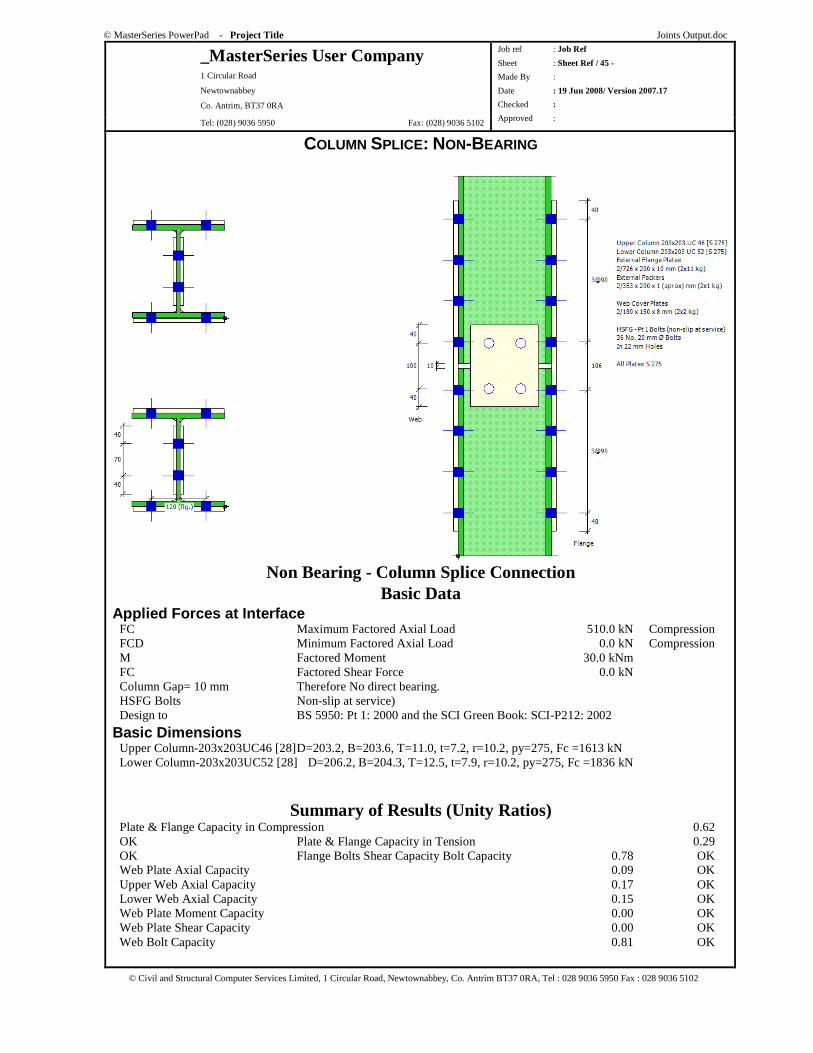
© MasterSeries PowerPad - Project Title Joints Output.doc
_MasterSeries User Company 1 Circular Road
Newtownabbey
Co. Antrim, BT37 0RA
Tel: (028) 9036 5950 Fax: (028) 9036 5102
Job ref : Job Ref
Sheet : Sheet Ref / 45 -
Made By :
Date : 19 Jun 2008/ Version 2007.17
Checked :
Approved :
© Civil and Structural Computer Services Limited, 1 Circular Road, Newtownabbey, Co. Antrim BT37 0RA, Tel : 028 9036 5950 Fax : 028 9036 5102
COLUMN SPLICE: NON-BEARING
Non Bearing - Column Splice Connection Basic Data
Applied Forces at Interface FC Maximum Factored Axial Load 510.0 kN Compression FCD Minimum Factored Axial Load 0.0 kN Compression M Factored Moment 30.0 kNm FC Factored Shear Force 0.0 kN Column Gap= 10 mm Therefore No direct bearing. HSFG Bolts Non-slip at service) Design to BS 5950: Pt 1: 2000 and the SCI Green Book: SCI-P212: 2002
Basic Dimensions Upper Column-203x203UC46 [28] D=203.2, B=203.6, T=11.0, t=7.2, r=10.2, py=275, Fc =1613 kN Lower Column-203x203UC52 [28] D=206.2, B=204.3, T=12.5, t=7.9, r=10.2, py=275, Fc =1836 kN
Summary of Results (Unity Ratios) Plate & Flange Capacity in Compression 0.62 OK Plate & Flange Capacity in Tension 0.29 OK Flange Bolts Shear Capacity Bolt Capacity 0.78 OK Web Plate Axial Capacity 0.09 OK Upper Web Axial Capacity 0.17 OK Lower Web Axial Capacity 0.15 OK Web Plate Moment Capacity 0.00 OK Web Plate Shear Capacity 0.00 OK Web Bolt Capacity 0.81 OK
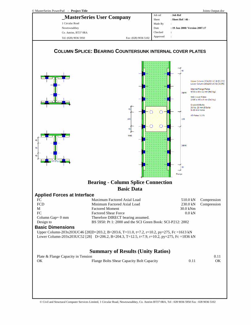
© MasterSeries PowerPad - Project Title Joints Output.doc
_MasterSeries User Company 1 Circular Road
Newtownabbey
Co. Antrim, BT37 0RA
Tel: (028) 9036 5950 Fax: (028) 9036 5102
Job ref : Job Ref
Sheet : Sheet Ref / 46 -
Made By :
Date : 19 Jun 2008/ Version 2007.17
Checked :
Approved :
© Civil and Structural Computer Services Limited, 1 Circular Road, Newtownabbey, Co. Antrim BT37 0RA, Tel : 028 9036 5950 Fax : 028 9036 5102
COLUMN SPLICE: BEARING COUNTERSUNK INTERNAL COVER PLATES
Bearing - Column Splice Connection Basic Data
Applied Forces at Interface FC Maximum Factored Axial Load 510.0 kN Compression FCD Minimum Factored Axial Load 230.0 kN Compression M Factored Moment 30.0 kNm FC Factored Shear Force 0.0 kN Column Gap= 0 mm Therefore DIRECT bearing assumed. Design to BS 5950: Pt 1: 2000 and the SCI Green Book: SCI-P212: 2002
Basic Dimensions Upper Column-203x203UC46 [28] D=203.2, B=203.6, T=11.0, t=7.2, r=10.2, py=275, Fc =1613 kN Lower Column-203x203UC52 [28] D=206.2, B=204.3, T=12.5, t=7.9, r=10.2, py=275, Fc =1836 kN
Summary of Results (Unity Ratios) Plate & Flange Capacity in Tension 0.11 OK Flange Bolts Shear Capacity Bolt Capacity 0.11 OK
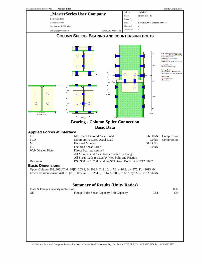
© MasterSeries PowerPad - Project Title Joints Output.doc
_MasterSeries User Company 1 Circular Road
Newtownabbey
Co. Antrim, BT37 0RA
Tel: (028) 9036 5950 Fax: (028) 9036 5102
Job ref : Job Ref
Sheet : Sheet Ref / 47 -
Made By :
Date : 19 Jun 2008/ Version 2007.17
Checked :
Approved :
© Civil and Structural Computer Services Limited, 1 Circular Road, Newtownabbey, Co. Antrim BT37 0RA, Tel : 028 9036 5950 Fax : 028 9036 5102
COLUMN SPLICE- BEARING AND COUNTERSUNK BOLTS
Bearing - Column Splice Connection Basic Data
Applied Forces at Interface FC Maximum Factored Axial Load 560.0 kN Compression FCD Minimum Factored Axial Load 0.0 kN Compression M Factored Moment 30.0 kNm FC Factored Shear Force 0.0 kN Web Divsion Plate Direct Bearing assumed All Moment and Axial loads resisted by Flanges All Shear loads resisted by Web bolts and Friction Design to BS 5950: Pt 1: 2000 and the SCI Green Book: SCI-P212: 2002
Basic Dimensions Upper Column-203x203UC46 [28] D=203.2, B=203.6, T=11.0, t=7.2, r=10.2, py=275, Fc =1613 kN Lower Column-254x254UC73 [28] D=254.1, B=254.6, T=14.2, t=8.6, r=12.7, py=275, Fc =2556 kN
Summary of Results (Unity Ratios) Plate & Flange Capacity in Tension 0.32 OK Flange Bolts Shear Capacity Bolt Capacity 0.51 OK
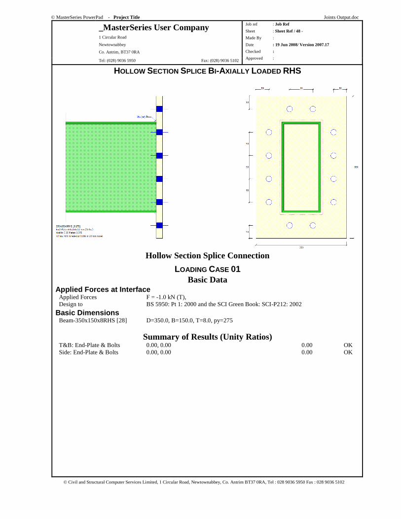
© MasterSeries PowerPad - Project Title Joints Output.doc
_MasterSeries User Company 1 Circular Road
Newtownabbey
Co. Antrim, BT37 0RA
Tel: (028) 9036 5950 Fax: (028) 9036 5102
Job ref : Job Ref
Sheet : Sheet Ref / 48 -
Made By :
Date : 19 Jun 2008/ Version 2007.17
Checked :
Approved :
© Civil and Structural Computer Services Limited, 1 Circular Road, Newtownabbey, Co. Antrim BT37 0RA, Tel : 028 9036 5950 Fax : 028 9036 5102
HOLLOW SECTION SPLICE BI-AXIALLY LOADED RHS
Hollow Section Splice Connection
LOADING CASE 01 Basic Data
Applied Forces at Interface Applied Forces F = -1.0 kN (T), Design to BS 5950: Pt 1: 2000 and the SCI Green Book: SCI-P212: 2002
Basic Dimensions Beam-350x150x8RHS [28] D=350.0, B=150.0, T=8.0, py=275
Summary of Results (Unity Ratios) T&B: End-Plate & Bolts 0.00, 0.00 0.00 OK Side: End-Plate & Bolts 0.00, 0.00 0.00 OK
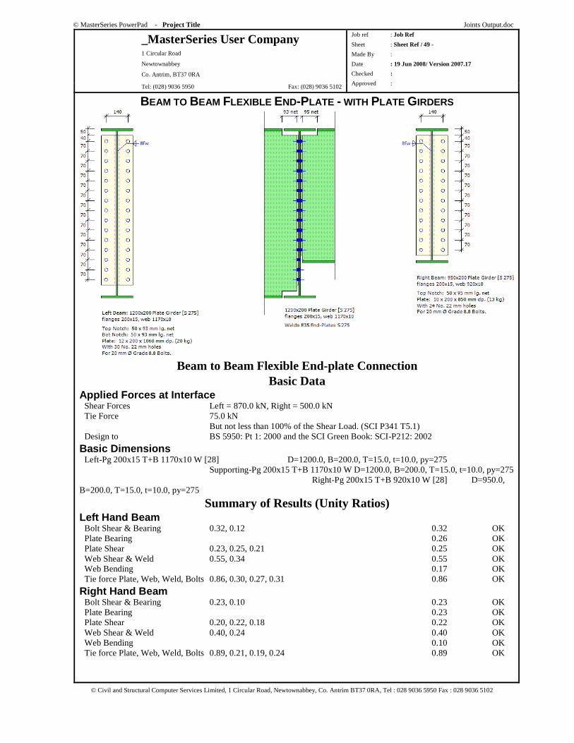
© MasterSeries PowerPad - Project Title Joints Output.doc
_MasterSeries User Company 1 Circular Road
Newtownabbey
Co. Antrim, BT37 0RA
Tel: (028) 9036 5950 Fax: (028) 9036 5102
Job ref : Job Ref
Sheet : Sheet Ref / 49 -
Made By :
Date : 19 Jun 2008/ Version 2007.17
Checked :
Approved :
© Civil and Structural Computer Services Limited, 1 Circular Road, Newtownabbey, Co. Antrim BT37 0RA, Tel : 028 9036 5950 Fax : 028 9036 5102
BEAM TO BEAM FLEXIBLE END-PLATE - WITH PLATE GIRDERS
Beam to Beam Flexible End-plate Connection Basic Data
Applied Forces at Interface Shear Forces Left = 870.0 kN, Right = 500.0 kN Tie Force 75.0 kN But not less than 100% of the Shear Load. (SCI P341 T5.1) Design to BS 5950: Pt 1: 2000 and the SCI Green Book: SCI-P212: 2002
Basic Dimensions Left-Pg 200x15 T+B 1170x10 W [28] D=1200.0, B=200.0, T=15.0, t=10.0, py=275 Supporting-Pg 200x15 T+B 1170x10 W D=1200.0, B=200.0, T=15.0, t=10.0, py=275 Right-Pg 200x15 T+B 920x10 W [28] D=950.0, B=200.0, T=15.0, t=10.0, py=275
Summary of Results (Unity Ratios) Left Hand Beam Bolt Shear & Bearing 0.32, 0.12 0.32 OK Plate Bearing 0.26 OK Plate Shear 0.23, 0.25, 0.21 0.25 OK Web Shear & Weld 0.55, 0.34 0.55 OK Web Bending 0.17 OK Tie force Plate, Web, Weld, Bolts 0.86, 0.30, 0.27, 0.31 0.86 OK
Right Hand Beam Bolt Shear & Bearing 0.23, 0.10 0.23 OK Plate Bearing 0.23 OK Plate Shear 0.20, 0.22, 0.18 0.22 OK Web Shear & Weld 0.40, 0.24 0.40 OK Web Bending 0.10 OK Tie force Plate, Web, Weld, Bolts 0.89, 0.21, 0.19, 0.24 0.89 OK

© MasterSeries PowerPad - Project Title Joints Output.doc
_MasterSeries User Company 1 Circular Road
Newtownabbey
Co. Antrim, BT37 0RA
Tel: (028) 9036 5950 Fax: (028) 9036 5102
Job ref : Job Ref
Sheet : Sheet Ref / 50 -
Made By :
Date : 19 Jun 2008/ Version 2007.17
Checked :
Approved :
© Civil and Structural Computer Services Limited, 1 Circular Road, Newtownabbey, Co. Antrim BT37 0RA, Tel : 028 9036 5950 Fax : 028 9036 5102
Supporting Beam Bolt Bearing 0.25 OK Plate Bearing 0.54 OK Web Bearing & Shear 0.54, 0.39, 0.39 0.54 OK
BEAM TO BEAM FIN-PLATE
Beam to Beam Fin-plate Connection Basic Data
Applied Forces at Interface Shear Forces Left = 200.0 kN, Right = 370.0 kN Tie Force 75.0 kN But not less than 100% of the Shear Load. (SCI P341 T5.1) Design to BS 5950: Pt 1: 2000 and the SCI Green Book: SCI-P212: 2002
Basic Dimensions Left-457x152 UB 67 [28] D=458.0, B=153.8, T=15.0, t=9.0, r=10.2, py=275 Supporting-533x210 UB 82 [28] D=528.3, B=208.8, T=13.2, t=9.6, r=12.7, py=275 Right-457x152 UB 67 [28] D=458.0, B=153.8, T=15.0, t=9.0, r=10.2, py=275
Summary of Results (Unity Ratios) Left Hand Beam Bolt Shear & Bearing 0.54, 0.27 0.54 OK Fin-Plate & Web Bearing 0.53, 0.59 0.59 OK Beam Web Shear 0.31, 0.30, 0.38 0.38 OK Beam Web Bending 0.20 OK Fin-Plate Shear 0.37, 0.40, 0.33 0.40 OK Fin-Plate Bending 0.17, 0 0.17 OK Tie force Plate T,B, Web T, B 0.24, 0.35, 0.32, 0.48 0.48 OK
Right Hand Beam Bolt Shear & Bearing 0.90, 0.46 0.90 OK Fin-Plate & Web Bearing 0.90, 1.00 1.00 OK Beam Web Shear 0.58, 0.64, 0.57 0.64 OK
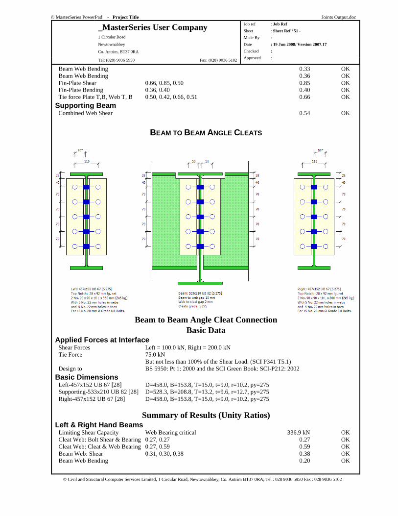
© MasterSeries PowerPad - Project Title Joints Output.doc
_MasterSeries User Company 1 Circular Road
Newtownabbey
Co. Antrim, BT37 0RA
Tel: (028) 9036 5950 Fax: (028) 9036 5102
Job ref : Job Ref
Sheet : Sheet Ref / 51 -
Made By :
Date : 19 Jun 2008/ Version 2007.17
Checked :
Approved :
© Civil and Structural Computer Services Limited, 1 Circular Road, Newtownabbey, Co. Antrim BT37 0RA, Tel : 028 9036 5950 Fax : 028 9036 5102
Beam Web Bending 0.33 OK Beam Web Bending 0.36 OK Fin-Plate Shear 0.66, 0.85, 0.50 0.85 OK Fin-Plate Bending 0.36, 0.40 0.40 OK Tie force Plate T,B, Web T, B 0.50, 0.42, 0.66, 0.51 0.66 OK
Supporting Beam Combined Web Shear 0.54 OK
BEAM TO BEAM ANGLE CLEATS
Beam to Beam Angle Cleat Connection Basic Data
Applied Forces at Interface Shear Forces Left = 100.0 kN, Right = 200.0 kN Tie Force 75.0 kN But not less than 100% of the Shear Load. (SCI P341 T5.1) Design to BS 5950: Pt 1: 2000 and the SCI Green Book: SCI-P212: 2002
Basic Dimensions Left-457x152 UB 67 [28] D=458.0, B=153.8, T=15.0, t=9.0, r=10.2, py=275 Supporting-533x210 UB 82 [28] D=528.3, B=208.8, T=13.2, t=9.6, r=12.7, py=275 Right-457x152 UB 67 [28] D=458.0, B=153.8, T=15.0, t=9.0, r=10.2, py=275
Summary of Results (Unity Ratios) Left & Right Hand Beams Limiting Shear Capacity Web Bearing critical 336.9 kN OK Cleat Web: Bolt Shear & Bearing 0.27, 0.27 0.27 OK Cleat Web: Cleat & Web Bearing 0.27, 0.59 0.59 OK Beam Web: Shear 0.31, 0.30, 0.38 0.38 OK Beam Web Bending 0.20 OK
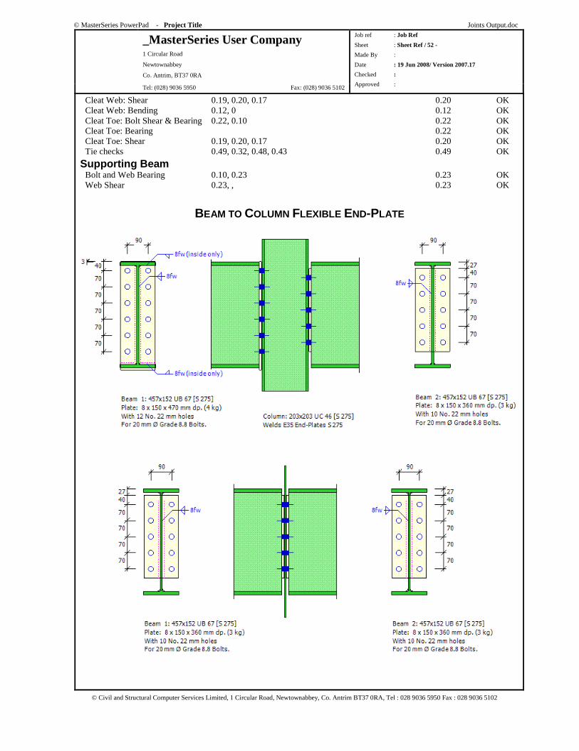
© MasterSeries PowerPad - Project Title Joints Output.doc
_MasterSeries User Company 1 Circular Road
Newtownabbey
Co. Antrim, BT37 0RA
Tel: (028) 9036 5950 Fax: (028) 9036 5102
Job ref : Job Ref
Sheet : Sheet Ref / 52 -
Made By :
Date : 19 Jun 2008/ Version 2007.17
Checked :
Approved :
© Civil and Structural Computer Services Limited, 1 Circular Road, Newtownabbey, Co. Antrim BT37 0RA, Tel : 028 9036 5950 Fax : 028 9036 5102
Cleat Web: Shear 0.19, 0.20, 0.17 0.20 OK Cleat Web: Bending 0.12, 0 0.12 OK Cleat Toe: Bolt Shear & Bearing 0.22, 0.10 0.22 OK Cleat Toe: Bearing 0.22 OK Cleat Toe: Shear 0.19, 0.20, 0.17 0.20 OK Tie checks 0.49, 0.32, 0.48, 0.43 0.49 OK
Supporting Beam Bolt and Web Bearing 0.10, 0.23 0.23 OK Web Shear 0.23, , 0.23 OK
BEAM TO COLUMN FLEXIBLE END-PLATE
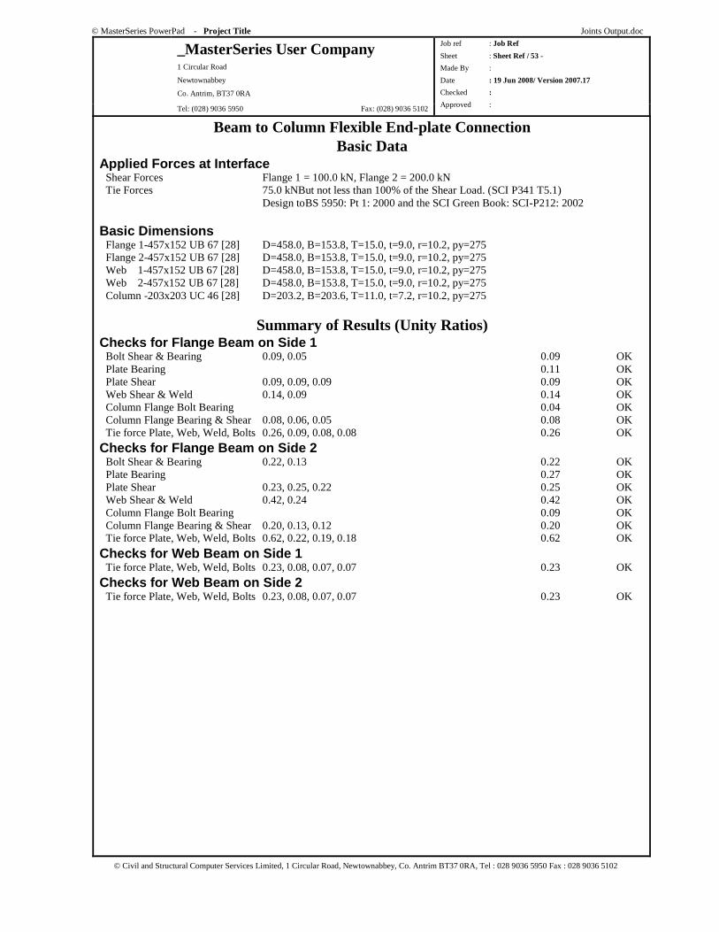
© MasterSeries PowerPad - Project Title Joints Output.doc
_MasterSeries User Company 1 Circular Road
Newtownabbey
Co. Antrim, BT37 0RA
Tel: (028) 9036 5950 Fax: (028) 9036 5102
Job ref : Job Ref
Sheet : Sheet Ref / 53 -
Made By :
Date : 19 Jun 2008/ Version 2007.17
Checked :
Approved :
© Civil and Structural Computer Services Limited, 1 Circular Road, Newtownabbey, Co. Antrim BT37 0RA, Tel : 028 9036 5950 Fax : 028 9036 5102
Beam to Column Flexible End-plate Connection Basic Data
Applied Forces at Interface Shear Forces Flange 1 = 100.0 kN, Flange 2 = 200.0 kN Tie Forces 75.0 kNBut not less than 100% of the Shear Load. (SCI P341 T5.1) Design toBS 5950: Pt 1: 2000 and the SCI Green Book: SCI-P212: 2002
Basic Dimensions Flange 1-457x152 UB 67 [28] D=458.0, B=153.8, T=15.0, t=9.0, r=10.2, py=275 Flange 2-457x152 UB 67 [28] D=458.0, B=153.8, T=15.0, t=9.0, r=10.2, py=275 Web 1-457x152 UB 67 [28] D=458.0, B=153.8, T=15.0, t=9.0, r=10.2, py=275 Web 2-457x152 UB 67 [28] D=458.0, B=153.8, T=15.0, t=9.0, r=10.2, py=275 Column -203x203 UC 46 [28] D=203.2, B=203.6, T=11.0, t=7.2, r=10.2, py=275
Summary of Results (Unity Ratios) Checks for Flange Beam on Side 1 Bolt Shear & Bearing 0.09, 0.05 0.09 OK Plate Bearing 0.11 OK Plate Shear 0.09, 0.09, 0.09 0.09 OK Web Shear & Weld 0.14, 0.09 0.14 OK Column Flange Bolt Bearing 0.04 OK Column Flange Bearing & Shear 0.08, 0.06, 0.05 0.08 OK Tie force Plate, Web, Weld, Bolts 0.26, 0.09, 0.08, 0.08 0.26 OK
Checks for Flange Beam on Side 2 Bolt Shear & Bearing 0.22, 0.13 0.22 OK Plate Bearing 0.27 OK Plate Shear 0.23, 0.25, 0.22 0.25 OK Web Shear & Weld 0.42, 0.24 0.42 OK Column Flange Bolt Bearing 0.09 OK Column Flange Bearing & Shear 0.20, 0.13, 0.12 0.20 OK Tie force Plate, Web, Weld, Bolts 0.62, 0.22, 0.19, 0.18 0.62 OK
Checks for Web Beam on Side 1 Tie force Plate, Web, Weld, Bolts 0.23, 0.08, 0.07, 0.07 0.23 OK
Checks for Web Beam on Side 2 Tie force Plate, Web, Weld, Bolts 0.23, 0.08, 0.07, 0.07 0.23 OK
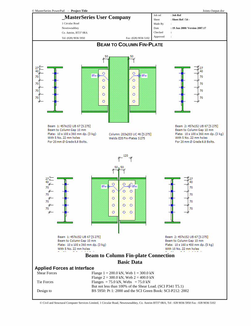
© MasterSeries PowerPad - Project Title Joints Output.doc
_MasterSeries User Company 1 Circular Road
Newtownabbey
Co. Antrim, BT37 0RA
Tel: (028) 9036 5950 Fax: (028) 9036 5102
Job ref : Job Ref
Sheet : Sheet Ref / 54 -
Made By :
Date : 19 Jun 2008/ Version 2007.17
Checked :
Approved :
© Civil and Structural Computer Services Limited, 1 Circular Road, Newtownabbey, Co. Antrim BT37 0RA, Tel : 028 9036 5950 Fax : 028 9036 5102
BEAM TO COLUMN FIN-PLATE
Beam to Column Fin-plate Connection Basic Data
Applied Forces at Interface Shear Forces Flange 1 = 200.0 kN, Web 1 = 300.0 kN Flange 2 = 300.0 kN, Web 2 = 400.0 kN Tie Forces Flanges = 75.0 kN, Webs = 75.0 kN But not less than 100% of the Shear Load. (SCI P341 T5.1) Design to BS 5950: Pt 1: 2000 and the SCI Green Book: SCI-P212: 2002
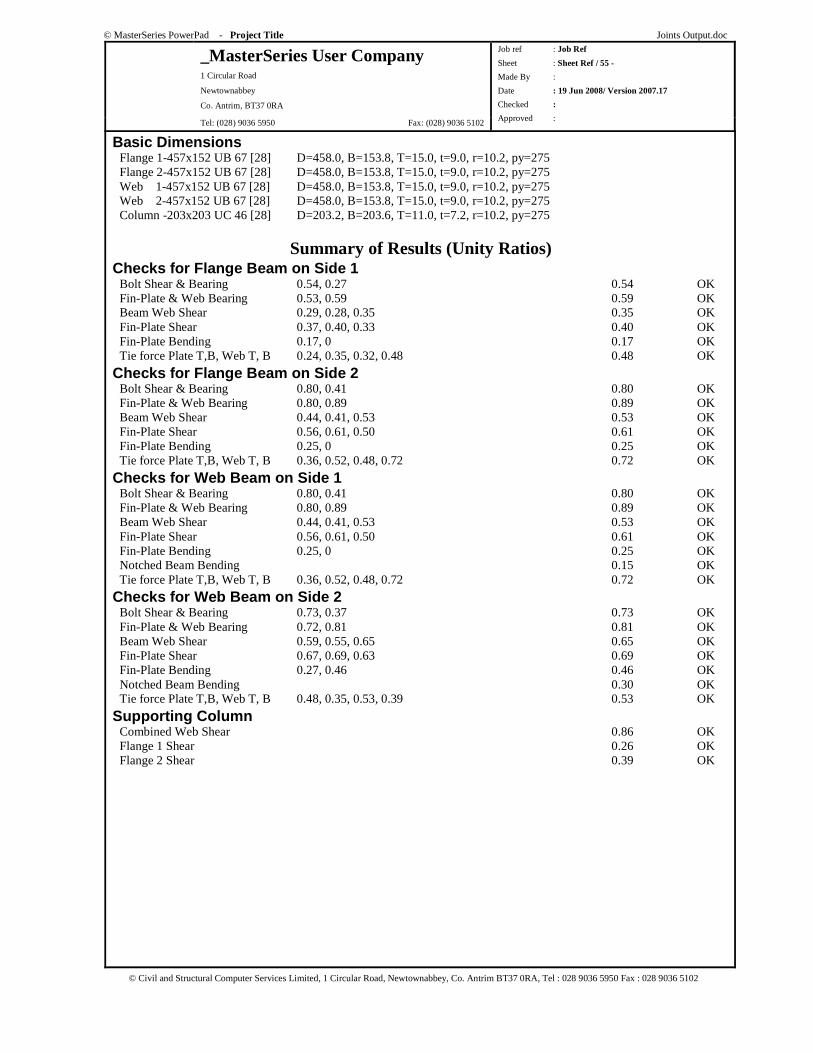
© MasterSeries PowerPad - Project Title Joints Output.doc
_MasterSeries User Company 1 Circular Road
Newtownabbey
Co. Antrim, BT37 0RA
Tel: (028) 9036 5950 Fax: (028) 9036 5102
Job ref : Job Ref
Sheet : Sheet Ref / 55 -
Made By :
Date : 19 Jun 2008/ Version 2007.17
Checked :
Approved :
© Civil and Structural Computer Services Limited, 1 Circular Road, Newtownabbey, Co. Antrim BT37 0RA, Tel : 028 9036 5950 Fax : 028 9036 5102
Basic Dimensions Flange 1-457x152 UB 67 [28] D=458.0, B=153.8, T=15.0, t=9.0, r=10.2, py=275 Flange 2-457x152 UB 67 [28] D=458.0, B=153.8, T=15.0, t=9.0, r=10.2, py=275 Web 1-457x152 UB 67 [28] D=458.0, B=153.8, T=15.0, t=9.0, r=10.2, py=275 Web 2-457x152 UB 67 [28] D=458.0, B=153.8, T=15.0, t=9.0, r=10.2, py=275 Column -203x203 UC 46 [28] D=203.2, B=203.6, T=11.0, t=7.2, r=10.2, py=275
Summary of Results (Unity Ratios) Checks for Flange Beam on Side 1 Bolt Shear & Bearing 0.54, 0.27 0.54 OK Fin-Plate & Web Bearing 0.53, 0.59 0.59 OK Beam Web Shear 0.29, 0.28, 0.35 0.35 OK Fin-Plate Shear 0.37, 0.40, 0.33 0.40 OK Fin-Plate Bending 0.17, 0 0.17 OK Tie force Plate T,B, Web T, B 0.24, 0.35, 0.32, 0.48 0.48 OK
Checks for Flange Beam on Side 2 Bolt Shear & Bearing 0.80, 0.41 0.80 OK Fin-Plate & Web Bearing 0.80, 0.89 0.89 OK Beam Web Shear 0.44, 0.41, 0.53 0.53 OK Fin-Plate Shear 0.56, 0.61, 0.50 0.61 OK Fin-Plate Bending 0.25, 0 0.25 OK Tie force Plate T,B, Web T, B 0.36, 0.52, 0.48, 0.72 0.72 OK
Checks for Web Beam on Side 1 Bolt Shear & Bearing 0.80, 0.41 0.80 OK Fin-Plate & Web Bearing 0.80, 0.89 0.89 OK Beam Web Shear 0.44, 0.41, 0.53 0.53 OK Fin-Plate Shear 0.56, 0.61, 0.50 0.61 OK Fin-Plate Bending 0.25, 0 0.25 OK Notched Beam Bending 0.15 OK Tie force Plate T,B, Web T, B 0.36, 0.52, 0.48, 0.72 0.72 OK
Checks for Web Beam on Side 2 Bolt Shear & Bearing 0.73, 0.37 0.73 OK Fin-Plate & Web Bearing 0.72, 0.81 0.81 OK Beam Web Shear 0.59, 0.55, 0.65 0.65 OK Fin-Plate Shear 0.67, 0.69, 0.63 0.69 OK Fin-Plate Bending 0.27, 0.46 0.46 OK Notched Beam Bending 0.30 OK Tie force Plate T,B, Web T, B 0.48, 0.35, 0.53, 0.39 0.53 OK
Supporting Column Combined Web Shear 0.86 OK Flange 1 Shear 0.26 OK Flange 2 Shear 0.39 OK
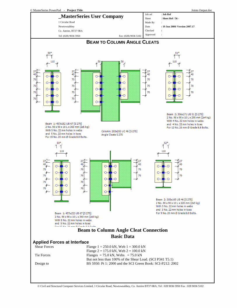
© MasterSeries PowerPad - Project Title Joints Output.doc
_MasterSeries User Company 1 Circular Road
Newtownabbey
Co. Antrim, BT37 0RA
Tel: (028) 9036 5950 Fax: (028) 9036 5102
Job ref : Job Ref
Sheet : Sheet Ref / 56 -
Made By :
Date : 19 Jun 2008/ Version 2007.17
Checked :
Approved :
© Civil and Structural Computer Services Limited, 1 Circular Road, Newtownabbey, Co. Antrim BT37 0RA, Tel : 028 9036 5950 Fax : 028 9036 5102
BEAM TO COLUMN ANGLE CLEATS
Beam to Column Angle Cleat Connection Basic Data
Applied Forces at Interface Shear Forces Flange 1 = 250.0 kN, Web 1 = 300.0 kN Flange 2 = 175.0 kN, Web 2 = 100.0 kN Tie Forces Flanges = 75.0 kN, Webs = 75.0 kN But not less than 100% of the Shear Load. (SCI P341 T5.1) Design to BS 5950: Pt 1: 2000 and the SCI Green Book: SCI-P212: 2002
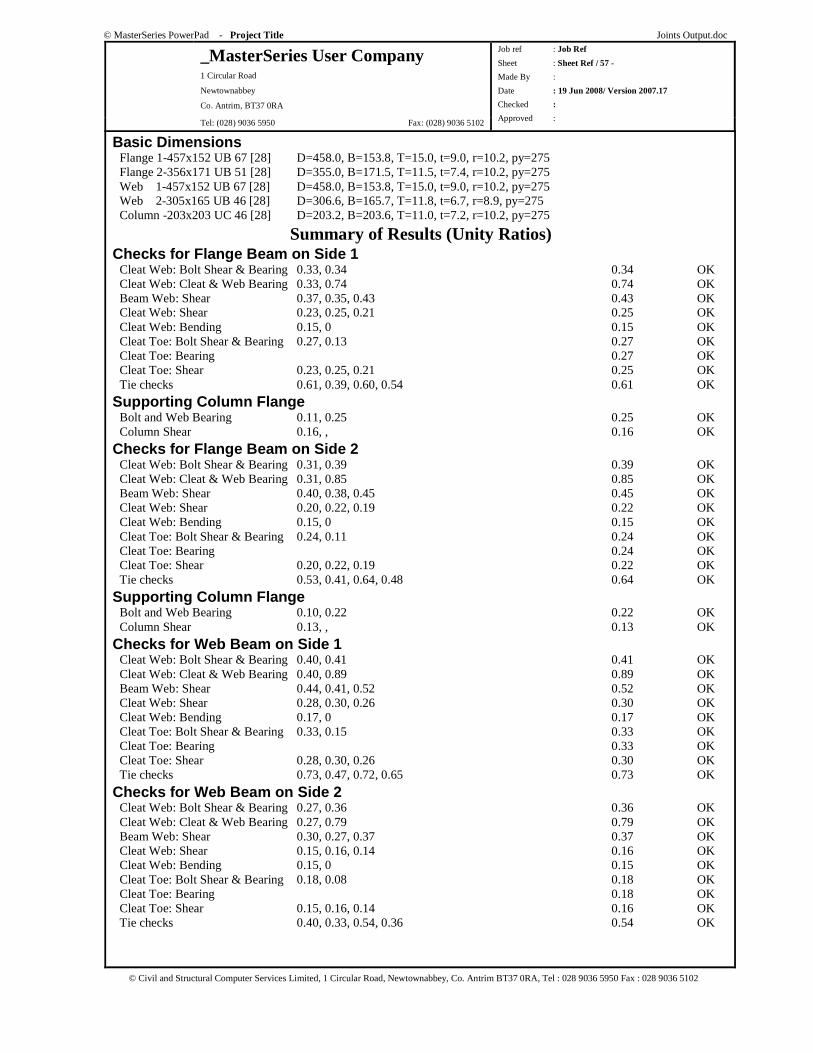
© MasterSeries PowerPad - Project Title Joints Output.doc
_MasterSeries User Company 1 Circular Road
Newtownabbey
Co. Antrim, BT37 0RA
Tel: (028) 9036 5950 Fax: (028) 9036 5102
Job ref : Job Ref
Sheet : Sheet Ref / 57 -
Made By :
Date : 19 Jun 2008/ Version 2007.17
Checked :
Approved :
© Civil and Structural Computer Services Limited, 1 Circular Road, Newtownabbey, Co. Antrim BT37 0RA, Tel : 028 9036 5950 Fax : 028 9036 5102
Basic Dimensions Flange 1-457x152 UB 67 [28] D=458.0, B=153.8, T=15.0, t=9.0, r=10.2, py=275 Flange 2-356x171 UB 51 [28] D=355.0, B=171.5, T=11.5, t=7.4, r=10.2, py=275 Web 1-457x152 UB 67 [28] D=458.0, B=153.8, T=15.0, t=9.0, r=10.2, py=275 Web 2-305x165 UB 46 [28] D=306.6, B=165.7, T=11.8, t=6.7, r=8.9, py=275 Column -203x203 UC 46 [28] D=203.2, B=203.6, T=11.0, t=7.2, r=10.2, py=275
Summary of Results (Unity Ratios) Checks for Flange Beam on Side 1 Cleat Web: Bolt Shear & Bearing 0.33, 0.34 0.34 OK Cleat Web: Cleat & Web Bearing 0.33, 0.74 0.74 OK Beam Web: Shear 0.37, 0.35, 0.43 0.43 OK Cleat Web: Shear 0.23, 0.25, 0.21 0.25 OK Cleat Web: Bending 0.15, 0 0.15 OK Cleat Toe: Bolt Shear & Bearing 0.27, 0.13 0.27 OK Cleat Toe: Bearing 0.27 OK Cleat Toe: Shear 0.23, 0.25, 0.21 0.25 OK Tie checks 0.61, 0.39, 0.60, 0.54 0.61 OK
Supporting Column Flange Bolt and Web Bearing 0.11, 0.25 0.25 OK Column Shear 0.16, , 0.16 OK
Checks for Flange Beam on Side 2 Cleat Web: Bolt Shear & Bearing 0.31, 0.39 0.39 OK Cleat Web: Cleat & Web Bearing 0.31, 0.85 0.85 OK Beam Web: Shear 0.40, 0.38, 0.45 0.45 OK Cleat Web: Shear 0.20, 0.22, 0.19 0.22 OK Cleat Web: Bending 0.15, 0 0.15 OK Cleat Toe: Bolt Shear & Bearing 0.24, 0.11 0.24 OK Cleat Toe: Bearing 0.24 OK Cleat Toe: Shear 0.20, 0.22, 0.19 0.22 OK Tie checks 0.53, 0.41, 0.64, 0.48 0.64 OK
Supporting Column Flange Bolt and Web Bearing 0.10, 0.22 0.22 OK Column Shear 0.13, , 0.13 OK
Checks for Web Beam on Side 1 Cleat Web: Bolt Shear & Bearing 0.40, 0.41 0.41 OK Cleat Web: Cleat & Web Bearing 0.40, 0.89 0.89 OK Beam Web: Shear 0.44, 0.41, 0.52 0.52 OK Cleat Web: Shear 0.28, 0.30, 0.26 0.30 OK Cleat Web: Bending 0.17, 0 0.17 OK Cleat Toe: Bolt Shear & Bearing 0.33, 0.15 0.33 OK Cleat Toe: Bearing 0.33 OK Cleat Toe: Shear 0.28, 0.30, 0.26 0.30 OK Tie checks 0.73, 0.47, 0.72, 0.65 0.73 OK
Checks for Web Beam on Side 2 Cleat Web: Bolt Shear & Bearing 0.27, 0.36 0.36 OK Cleat Web: Cleat & Web Bearing 0.27, 0.79 0.79 OK Beam Web: Shear 0.30, 0.27, 0.37 0.37 OK Cleat Web: Shear 0.15, 0.16, 0.14 0.16 OK Cleat Web: Bending 0.15, 0 0.15 OK Cleat Toe: Bolt Shear & Bearing 0.18, 0.08 0.18 OK Cleat Toe: Bearing 0.18 OK Cleat Toe: Shear 0.15, 0.16, 0.14 0.16 OK Tie checks 0.40, 0.33, 0.54, 0.36 0.54 OK
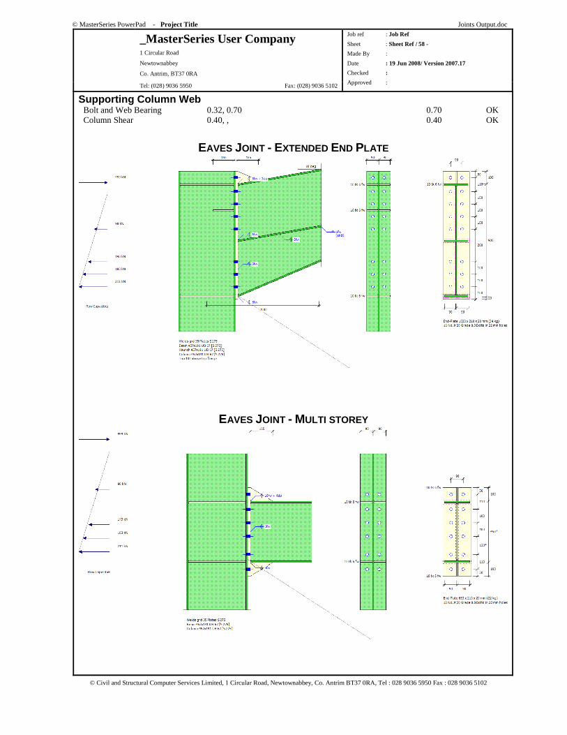
© MasterSeries PowerPad - Project Title Joints Output.doc
_MasterSeries User Company 1 Circular Road
Newtownabbey
Co. Antrim, BT37 0RA
Tel: (028) 9036 5950 Fax: (028) 9036 5102
Job ref : Job Ref
Sheet : Sheet Ref / 58 -
Made By :
Date : 19 Jun 2008/ Version 2007.17
Checked :
Approved :
© Civil and Structural Computer Services Limited, 1 Circular Road, Newtownabbey, Co. Antrim BT37 0RA, Tel : 028 9036 5950 Fax : 028 9036 5102
Supporting Column Web Bolt and Web Bearing 0.32, 0.70 0.70 OK Column Shear 0.40, , 0.40 OK
EAVES JOINT - EXTENDED END PLATE
EAVES JOINT - MULTI STOREY
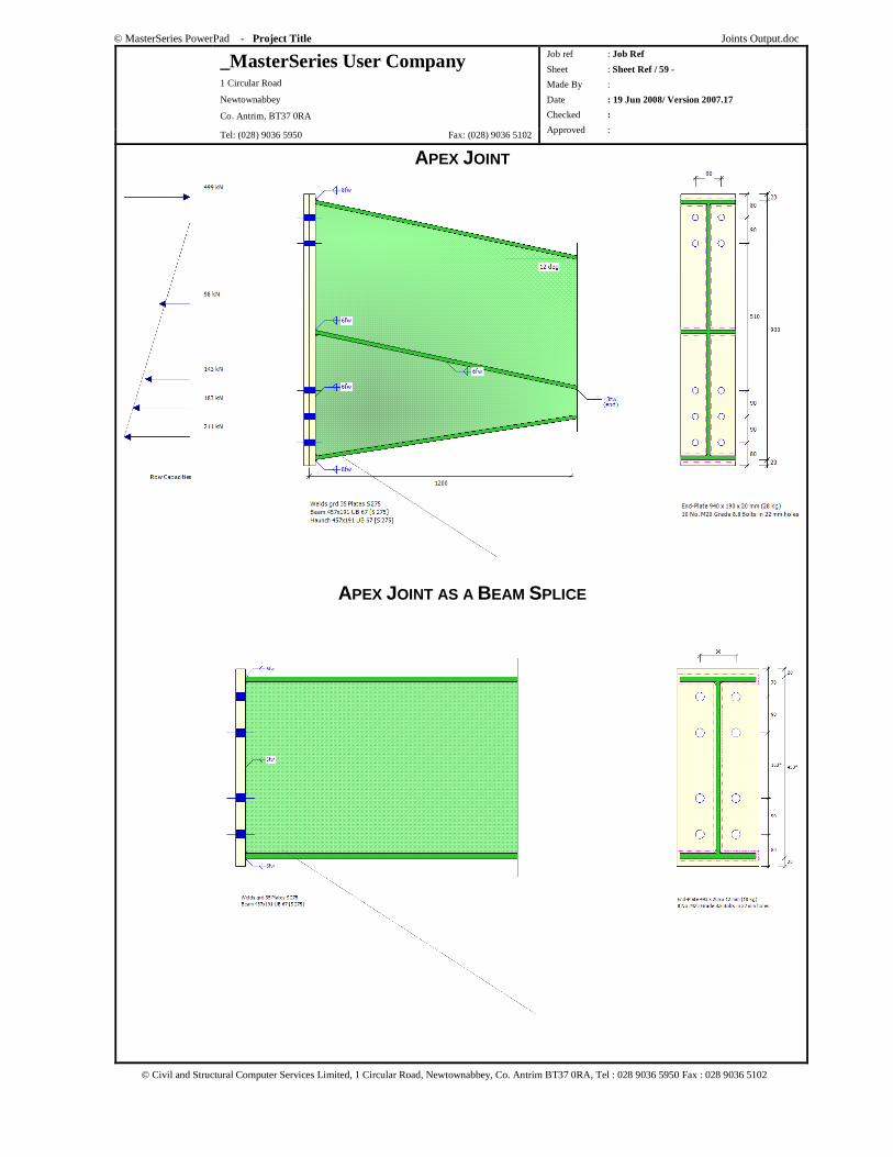
© MasterSeries PowerPad - Project Title Joints Output.doc
_MasterSeries User Company 1 Circular Road
Newtownabbey
Co. Antrim, BT37 0RA
Tel: (028) 9036 5950 Fax: (028) 9036 5102
Job ref : Job Ref
Sheet : Sheet Ref / 59 -
Made By :
Date : 19 Jun 2008/ Version 2007.17
Checked :
Approved :
© Civil and Structural Computer Services Limited, 1 Circular Road, Newtownabbey, Co. Antrim BT37 0RA, Tel : 028 9036 5950 Fax : 028 9036 5102
APEX JOINT
APEX JOINT AS A BEAM SPLICE
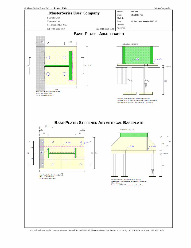
© MasterSeries PowerPad - Project Title Joints Output.doc
_MasterSeries User Company 1 Circular Road
Newtownabbey
Co. Antrim, BT37 0RA
Tel: (028) 9036 5950 Fax: (028) 9036 5102
Job ref : Job Ref
Sheet : Sheet Ref / 60 -
Made By :
Date : 19 Jun 2008/ Version 2007.17
Checked :
Approved :
© Civil and Structural Computer Services Limited, 1 Circular Road, Newtownabbey, Co. Antrim BT37 0RA, Tel : 028 9036 5950 Fax : 028 9036 5102
BASE-PLATE - AXIAL LOADED
BASE-PLATE: STIFFENED ASYMETRICAL BASEPLATE
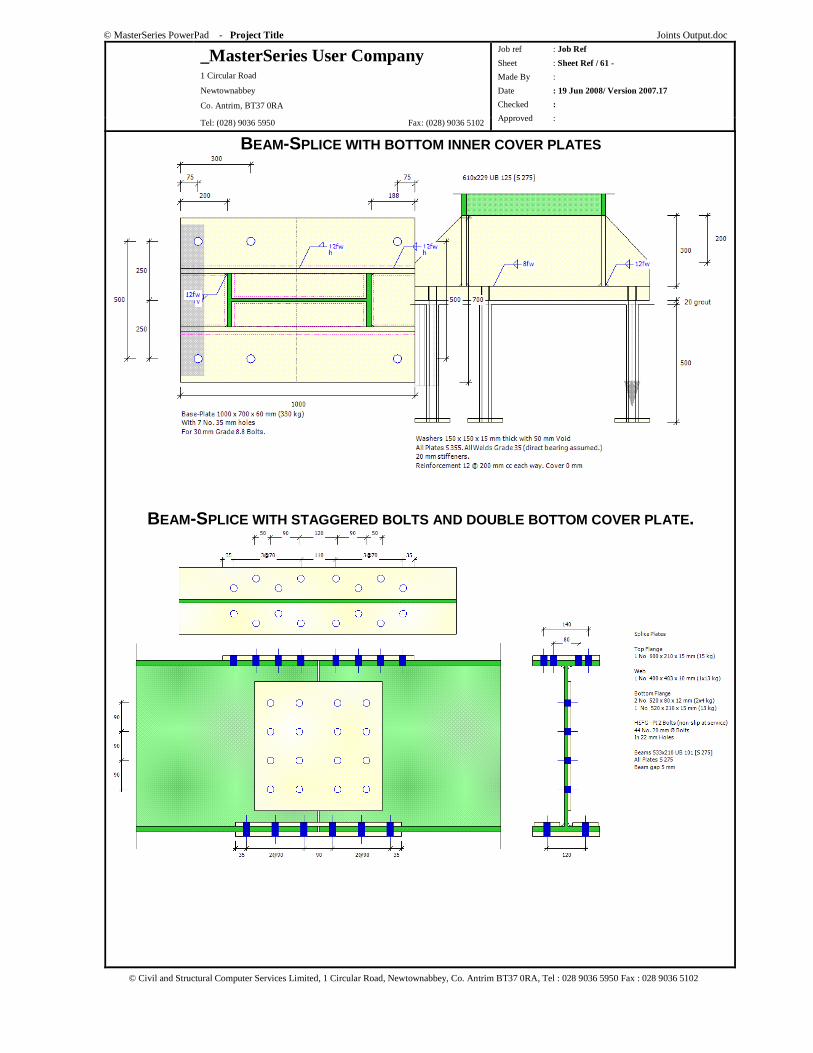
© MasterSeries PowerPad - Project Title Joints Output.doc
_MasterSeries User Company 1 Circular Road
Newtownabbey
Co. Antrim, BT37 0RA
Tel: (028) 9036 5950 Fax: (028) 9036 5102
Job ref : Job Ref
Sheet : Sheet Ref / 61 -
Made By :
Date : 19 Jun 2008/ Version 2007.17
Checked :
Approved :
© Civil and Structural Computer Services Limited, 1 Circular Road, Newtownabbey, Co. Antrim BT37 0RA, Tel : 028 9036 5950 Fax : 028 9036 5102
BEAM-SPLICE WITH BOTTOM INNER COVER PLATES
BEAM-SPLICE WITH STAGGERED BOLTS AND DOUBLE BOTTOM COVER PLATE.
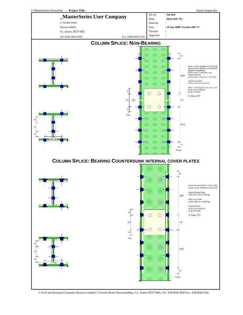
© MasterSeries PowerPad - Project Title Joints Output.doc
_MasterSeries User Company 1 Circular Road
Newtownabbey
Co. Antrim, BT37 0RA
Tel: (028) 9036 5950 Fax: (028) 9036 5102
Job ref : Job Ref
Sheet : Sheet Ref / 62 -
Made By :
Date : 19 Jun 2008/ Version 2007.17
Checked :
Approved :
© Civil and Structural Computer Services Limited, 1 Circular Road, Newtownabbey, Co. Antrim BT37 0RA, Tel : 028 9036 5950 Fax : 028 9036 5102
COLUMN SPLICE: NON-BEARING
COLUMN SPLICE: BEARING COUNTERSUNK INTERNAL COVER PLATES
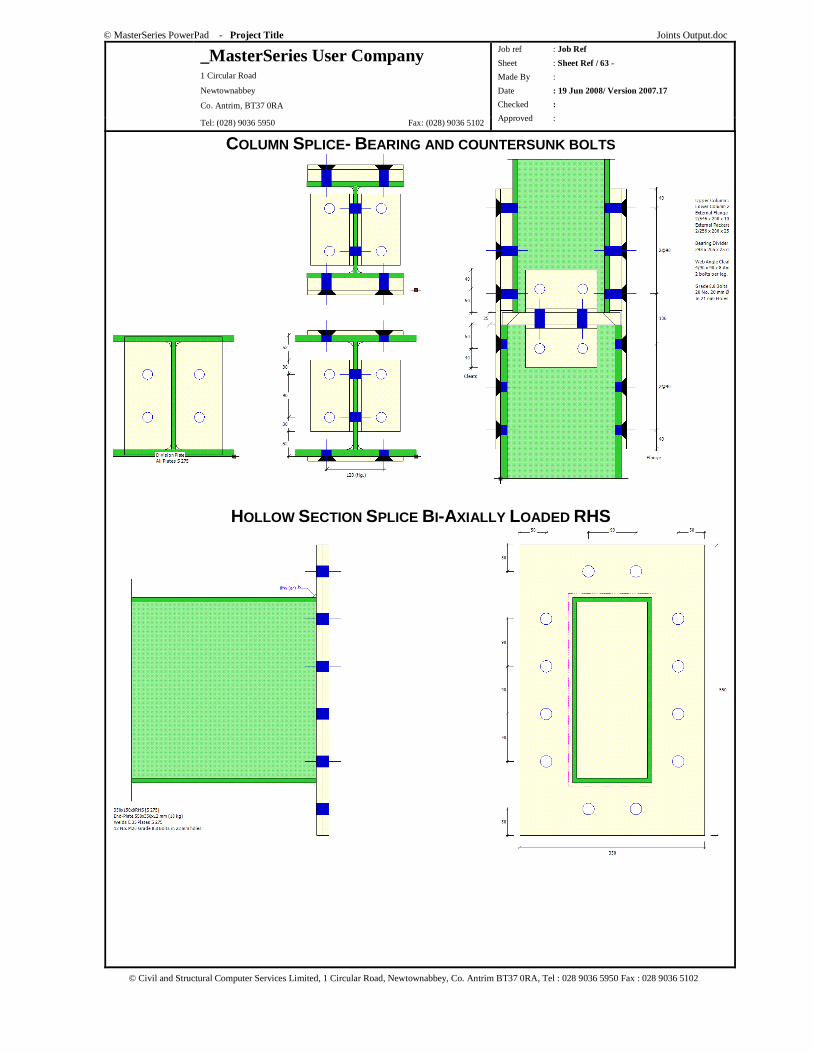
© MasterSeries PowerPad - Project Title Joints Output.doc
_MasterSeries User Company 1 Circular Road
Newtownabbey
Co. Antrim, BT37 0RA
Tel: (028) 9036 5950 Fax: (028) 9036 5102
Job ref : Job Ref
Sheet : Sheet Ref / 63 -
Made By :
Date : 19 Jun 2008/ Version 2007.17
Checked :
Approved :
© Civil and Structural Computer Services Limited, 1 Circular Road, Newtownabbey, Co. Antrim BT37 0RA, Tel : 028 9036 5950 Fax : 028 9036 5102
COLUMN SPLICE- BEARING AND COUNTERSUNK BOLTS
HOLLOW SECTION SPLICE BI-AXIALLY LOADED RHS
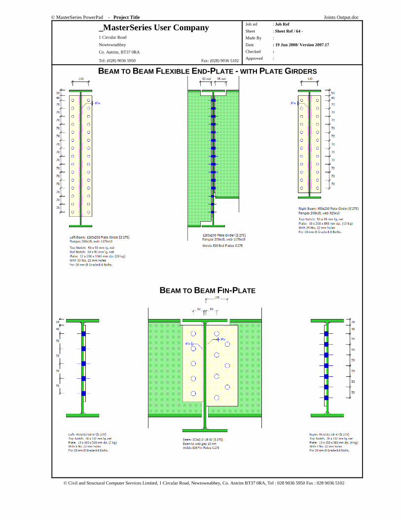
© MasterSeries PowerPad - Project Title Joints Output.doc
_MasterSeries User Company 1 Circular Road
Newtownabbey
Co. Antrim, BT37 0RA
Tel: (028) 9036 5950 Fax: (028) 9036 5102
Job ref : Job Ref
Sheet : Sheet Ref / 64 -
Made By :
Date : 19 Jun 2008/ Version 2007.17
Checked :
Approved :
© Civil and Structural Computer Services Limited, 1 Circular Road, Newtownabbey, Co. Antrim BT37 0RA, Tel : 028 9036 5950 Fax : 028 9036 5102
BEAM TO BEAM FLEXIBLE END-PLATE - WITH PLATE GIRDERS
BEAM TO BEAM FIN-PLATE
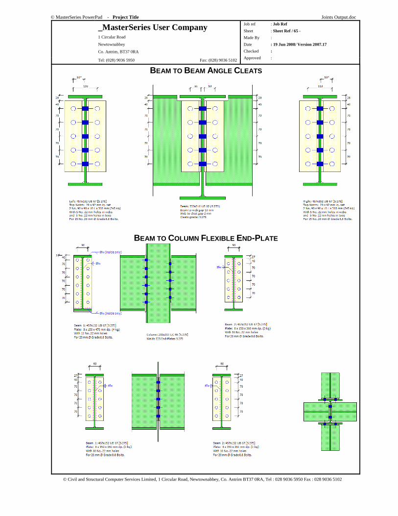
© MasterSeries PowerPad - Project Title Joints Output.doc
_MasterSeries User Company 1 Circular Road
Newtownabbey
Co. Antrim, BT37 0RA
Tel: (028) 9036 5950 Fax: (028) 9036 5102
Job ref : Job Ref
Sheet : Sheet Ref / 65 -
Made By :
Date : 19 Jun 2008/ Version 2007.17
Checked :
Approved :
© Civil and Structural Computer Services Limited, 1 Circular Road, Newtownabbey, Co. Antrim BT37 0RA, Tel : 028 9036 5950 Fax : 028 9036 5102
BEAM TO BEAM ANGLE CLEATS
BEAM TO COLUMN FLEXIBLE END-PLATE
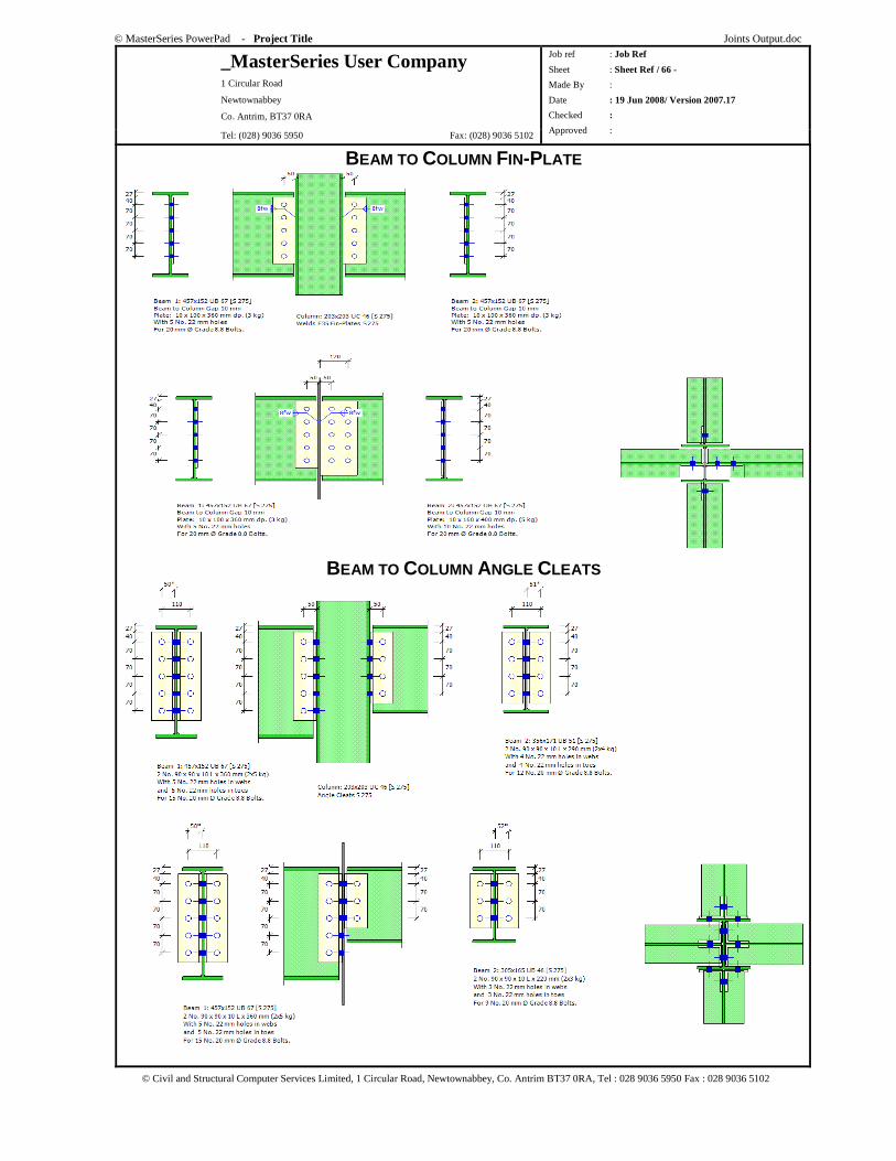
© MasterSeries PowerPad - Project Title Joints Output.doc
_MasterSeries User Company 1 Circular Road
Newtownabbey
Co. Antrim, BT37 0RA
Tel: (028) 9036 5950 Fax: (028) 9036 5102
Job ref : Job Ref
Sheet : Sheet Ref / 66 -
Made By :
Date : 19 Jun 2008/ Version 2007.17
Checked :
Approved :
© Civil and Structural Computer Services Limited, 1 Circular Road, Newtownabbey, Co. Antrim BT37 0RA, Tel : 028 9036 5950 Fax : 028 9036 5102
BEAM TO COLUMN FIN-PLATE
BEAM TO COLUMN ANGLE CLEATS